Pentair 368 Notice D'utilisation
Masquer les pouces
Voir aussi pour 368:
- Manuel d'installation (66 pages) ,
- Manuel d'installation (66 pages)

Manuels Connexes pour Pentair 368


Sommaire des Matières pour Pentair 368
- Page 1 Operation Manual Notice d’utilisation Manual de instrucciones Bedienungsanleitung Manuale d’uso Handleiding Rev B...
-
Page 2: Table Des Matières
Table of Contents Safety Information Specifications Valve Layout Installation Control Operation & Layout Programming Manual Regeneration Quick Cycling the Control System Selection and Reset Procedure Cycle Defaults Table Troubleshooting Icons That Appear In This Manual NOTE: Helpful hint to simplify procedure. WARNING: Failure to follow this instruction can result in personal injury or damage to the equipment. Pentair Residential Filtration, LLC Rev B... -
Page 3: Safety Information
• M inimum pipe run to water heater of three meters to prevent backup of hot water into system. • D o not use petroleum-based lubricants, oils or hydrocarbon-based lubricants. Use only 100% silicone lubricants. • U se only the power transformer supplied with this water conditioning system. • The power outlet must be grounded.. • I nstall an appropriate grounding strap across the inlet and outlet piping of the water conditioning system to ensure that a proper ground is maintained. • To disconnect power, unplug the AC adapter from its power source. • O bserve drain line requirements. The drain line must be a minimum of 12.7 mm (1/2”) diameter. Use 19.05 mm (3/4”) pipe if the total length of the drain line exceeds 6 meters. • D o not support the weight of the system on the control valve connections, or plumbing. • Use only regenerants designed for water conditioning. *Teflon is a trademark of E. I. duPont de Memours Pentair Residential Filtration, LLC Rev B... -
Page 4: Specifications
Refill Flow Rate ..................0.53Lpm (0.14GPM) / 1.25 Lpm (0.33GPM) * Recommended for indoor use only Options/Accessories (6 to 10 inch diameter tanks) Regenerant Injectors ........................... E, F, G, H and J External Drain Line Flow Controls ............3.8, 4.9, 6.4, 8.3 Lpm (1.0, 1.3, 1.7, 2.2 GPM) SERVICE Kv = 3.7 BW Kv = 0.48 SERVICE Cv = 4.3 BW Cv = 0.56 Pentair Residential Filtration, LLC Rev B... -
Page 5: Valve Layout
Valve Layout Injector/Screen Refill Control Figure 2 Outlet Inlet Backwash Bypass 3/4” BSPT 3/4” BSPT Brine Meter Drain Brine Inlet Drain Outlet Cable 1/2” BSPT 3/8” BSPT Figure 3 Pentair Residential Filtration, LLC Rev B... -
Page 6: Installation
Installation Figure 4 Drain Line Flow Control The drain line flow control (DLFC) requires assembly (Figure 5). 1. Locate parts and a roll of Teflon tape. The plumbing adapters should be removed (Figure 7 Connector Assembly). 2. Wrap the tape over threads of the flow control. 3. Screw the flow control and the 90° elbow together. Hand tighten. 4. Place the ball into the flow control and insert the assembly into the drain line opening. 5. Push the assembly in and secure with the drain line clip. Figure 5 Pentair Residential Filtration, LLC Rev B... - Page 7 Water Line Connection Once you have selected your location check the direction of the water flow in the main pipe. Inspect the main water pipe. Write down the type of pipe (copper, plastic, galvanized etc.). Record the size of the pipe. Plastic style pipes usually have the size printed on the outside. Other pipes can be measured for the out- side diameter and converted into the pipe size at the store. Do not use pipe that is smaller than the main water pipe. If the main plumbing is galvanized pipe and you are installingcopper pipe, then you must use dielectric insulating connectors between the two styles of pipe WARNING: If pipes will be sweat soldered, do not connect adapters to the bypass until the pipes have cooled. Figure 6 Bypass Operation IMPORTANT: When the valve is in bypass, water will not enter the softening tank. The water in the building will not be treated. Figure 6 Bypass Operation, shows the handles in the service position. WARNING : The inlet water must be connected to the inlet port of the valve. When replacing a water valve, it is possible that the inlet and outlet plumbing is installed in a reversed position. Be certain the inlet connection on the valve is connected to the incoming water fitting from the water supply. Do not solder pipes with lead-based solder. WARNING: Do not use petroleum grease on gaskets when connecting bypass plumbing. Use only 100% silicone grease products when installing any plastic valve. Non-silicone grease may cause plastic components to fail over time. Pentair Residential Filtration, LLC Rev B...
- Page 8 The bypass assembly connects to the water system by means of a connector assembly. The connector is secured to the plumbing and then inserted into the bypass. A clip is used to old it in place. Figure 7 Connector Assembly Before inserting the connector: • Check that all O-rings are in place and not damaged. • O-rings are pre-lubricated. Sliding surfaces should be lubricated with 100% silicone grease. Firmly insert connector into bypass. Press locking clip into position. Make certain the clip is fully engaged. NOTE: Before turning on the water to the valve, rotate the two handles on the bypass valve 2-3 times. This will help seat O-rings and prevent leaking. To remove a clip: 1. Turn off water and release water pressure at the valve. 2. Push the water line connectors into the bypass and valve. This will help release O-rings that may have seated in place. 3. Remove the clip by inserting a flat blade under the top center of the clip and lifting (prying up) (Figure 7 Connector Assembly). WARNING : Do not use pliers to remove a clip. It is likely the clip will break. Pentair Residential Filtration, LLC Rev B...
-
Page 9: Drain Line Connection
Local codes may require changes to the following suggestions. Check with local au- thorities before installing a system. 1. The unit should be above and not more than 6.1 m (20 feet) from the drain. Use an appropriate adapter fitting to connect 13 mm (1/2-inch) plastic tubing to the drain line connection of the control valve. 2. If the unit is located 6.1-12.2 m (20-40 feet) from drain, use 19 mm (3/4-inch) tubing. Use appropriate fittings to connect the 19 mm (3/4-inch) tubing to the 19 mm (3/4-inch) NPT drain connection on valve. 3. The drain line may be elevated up to 1.8 m (6 feet) providing the run does not exceed 4.6 m (15 feet) and water pressure at the softener is not less than 2.76 bar (40 psi). Elevation can increase by 610 mm (2 feet) for each additional 0.69 bar (10 psi) of water pressure at the drain connector. 4. Where the drain line is elevated but empties into a drain below the level of the control valve, form a 180 mm (7-inch) loop at the far end of the line so that the bottom of the loop is level with the drain line connection.This will provide an adequate siphon trap. Where the drain empties into an overhead sewer line, asink-type trap must be used. 5. Use pliers to expand a clamp. Slide the clamp up one end of the longer length drain line tubing about 2-5 cm (1-2 inches) and release. 6. Push the tubing over the ribbed drain line fitting. 7. Expand the clamp and move it up the tube to pinch the tube to the fitting. 8. Secure the discharge end of the drain line to prevent it from moving. NOTE: The drain line connects to the elbow previously installed. It is located between the water line connections at the rear of the valve. Right Way Figure 8 Drain Line with Air Gap NOTE: Waste connections or drain outlet shall be designed and constructed to provide for connection to the sanitary waste system through an air-gap of 2 pipe diameters or 22 mm (1 inch) whichever is larger. WARNING: Never insert drain line directly into a drain, sewer line or trap (Figure 8). Always allow an air gap between the drain line and the wastewater to prevent the possibility of sewage being back-siphoned into the conditioner. Pentair Residential Filtration, LLC Rev B... -
Page 10: Regenerant Line Connections
Regenerant Line Connections Make the connections and hand tighten. Be sure that the regenerant line is secure and free from air leaks. Even a small leak may prevent the conditioner from drawing the regenerant from the tank. This may also introduce air into the valve causing problems with valve operation. Ensure that Teflon* tape pipe sealant is applied to the 9.525 mm (3/8-inch) BSP regenerant line connection *Teflon is a trademark of E. I. duPont de Nemours. Electrical Connection The 608 Series control operates on 12-volt alternating current power supply. This requires use of the Autotrol supplied AC adapter. A variety of AC adapters are available for different applications. Make sure power source matches the rating printed on the AC adapter. NOTE: The power source should be constant. Be certain the AC adapter is not on a switched outlet. Power interruptions longer than 6 hours may cause the control’s super capacitor to fully discharge and loose the Time of Day setting. When power is restored, the control will briefly display the two digit model number and then display the Time of Day setting as “0”. The Time of Day will need to be programmed. Pentair Residential Filtration, LLC Rev B... -
Page 11: Control Operation & Layout
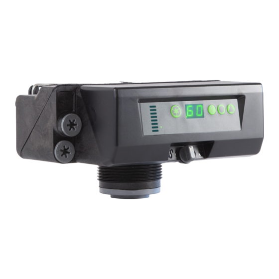
Time Button: When pressed will display the current hour of day for 5 seconds. Press again to in- crease the hour of day by 1. Press and hold to change rapidly. Salt Button: Press to display the current setting (HE/HC) for 5 seconds. Press again during the 5 seconds to change the setting. Regen Setting button (day interval for 604 controllers, volumetric capacity for 606 controllers): report to programing section of the 604 and 606 controllers for more informations. Flow Indicator (606 only): The decimal point/flow indicator blinks on and off when water flow turns the meter. Power Loss Memory Retention: The controller features battery-free Time of Day retention during loss of power. The Time will remain in memory. Note: All other programmed parameters are stored in the flash memory and are retained during power outages. Flash memory retention is 100 years. Setting Button Figure 9 Drain Line with Air Gap Pentair Residential Filtration, LLC Rev B... -
Page 12: Programming - 368/604
Programming - 368/604 Time of Day: Press until desired hour appears. Release. Range: 0 through 23 hours Note: The elapsed minutes will reset to zero when the hours are changed. Regenerant Dosage: Press until desired regenerant dosage appears. Release. Range: 0.20 kg to 6.0 kg 0.20 kg to 1.0 kg by increments of 0.05 kg 1.0 kg to 3.0 kg by increments of 0.1 kg 3.0 kg to 60 kg by increments of 0.5 kg Default: 0.6kg Regen Interval: Press until desired interval appears. Release. Range: 0 through 30 0 = Disabled 0.3 = Regeneration every 8 hours: at 2, 10 and 18 hrs 0.5 = Regeneration every12 hours: at 2 and 14 hours 1 - 30 = Days (every 3 days in this example) 368/604 PROGRAMMING IS COMPLETE Pentair Residential Filtration, LLC Rev B... - Page 13 (12 increments) 1.0 m to 3.0 m by increments of 0.1 m (20 increments) 3.0 m to 5.0 m by increments of 0.2 m (10 increments) 5.0 m to 9.5 m by increments of 0.5 m (10 increments) 368/606 PROGRAMMING IS COMPLETE Calendar Override Setting The model 606 demand control needs a method to set days between regeneration for regulatory require- ments and for cases when the flow sensor has failed. Enter by holding and for 3 seconds. The programmed calendar override is displayed. Press to increase value. Values the same as 604. 0 = no calendar override 0.3 = Regeneration every 8 hours 0.5 = Regeneration every 12 hours 1-30 days between regeneration Default: 0 NOTE: During programming if a button is not pushed for 5 seconds, the control returns to the normal operation mode and displays the Time of Day. Pentair Residential Filtration, LLC Rev B...
-
Page 14: Manual Regeneration
(- -) as it cycles to backwash. The control will proceed through a complete regeneration. Quick Cycling the Control Quick Cycling: Press and hold for three seconds to initiate an immediate regeneration. The control will cycle to the backwash cycle. 1. Press and release the to display “C 1” 2. S imultaneously press then release and to move the control to the next cycle. 3. P ress and release the to display “- -” or the “C#”. Continued pressing of will switch the display between “- -” and “C#”.” 4. Repeat steps 2 and 3 to cycle through each position. Quick Cycle to Service Position: Simultaneously press and and hold for 3 seconds during any regeneration cycle. The control will skip the remaining regeneration cycles and return to the service position. The Time of Day will be displayed when the control reaches the service position. Pentair Residential Filtration, LLC Rev B... -
Page 15: System Selection And Reset Procedure
System u2 System u3 System u4 Cycle Bed Flow (minutes) (minutes) (minutes) (minutes) Direction Backwash ↑ Calculated Calculated Calculated Calculated Brine Draw Slow Rinse Repressurize None Fast Rinse 2nd Backwash ↑ 2nd Fast Rinse Brine Refill None Calculated Calculated Calculated Calculated Pentair Residential Filtration, LLC Rev B... -
Page 16: Accessing History Values
Accessing History Values The control features a review level that displays the operationhistory of the system. This is a great troubleshooting tool for the control valve. To access history values, press together Manual regen button with the Salt button and hold for 3 seconds to view the Diagnostic Codes. If a button is not pushed for 30 seconds the controller will exit the history NOTE: table. Press the Time button to increment through the table. When the desired code is reached, Press the Salt button to display the value. Some of the values have four digits 1, 2, 3, 4. Press the Salt button to display the first two (1, 2). Press the Water Hardness button to display the last two (3, 4). When the Salt button is pressed to view H2 the current flow rate will be displayed but not updated. Continue to press and release the Salt button every 5 seconds to update the display. The flow dot on the display will flash when there is flow thru turbine. Liter per minute Pentair Residential Filtration, LLC Rev B... - Page 17 WARNING: If opened too rapidly or too far, media may be lost out of the tank into the valve or the plumbing. In the 1/4 open position, you should hear air slowly escap- ing from the valve drain line. B. W hen all of the air has been purged from the media tank (water begins to flow steadily from the drain line), open the main supply valve all of the way. This will purge the final air from the tank. C. A llow water to run to drain until the water runs clear from the drain line. This purges any debris from the media bed. D. T urn off the water supply and let the system stand for about five minutes to allow any trapped air to escape from the media tank. 4. A dding water to the regenerant tank. A. F rom the service position press the button to initiate a manual regeneration. B. Q uick cycle the control to the Refill Cycle (C7). The control will place the appropriate amount of water into the brine tank, then return to the service position.. Pentair Residential Filtration, LLC Rev B...
- Page 18 A. F rom the service position press and hold button for 5 seconds to initiate an immediate manual regeneration. B. T he control will begin a manual regen and advance the control valve to the backwash cycle (C1). Press the and buttons to advance to the regenerant draw slow rinse cycle (C2) C. O bserve that water is being drawn from the regenerant tank. If the water level does not recede, check all regenerant line connections. 6. I f the water level is receding from the regenerant tank press the and buttons for 3 seconds to cycle the control back to the service position. 7. T urn on a faucet plumbed after the water conditioner. Run the faucet until the water runs clear. 8. Place regenerant material in the brine tank. WARNING: Ensure that the system has been properly disinfected per the water condi- tioning system manufacturer’s recommendations. The Water Conditioning System is Now Fully Operational The display will show the hour of the day. The decimal point at bottom center of the display will blink when water is flowing.. Pentair Residential Filtration, LLC Rev B...
- Page 19 Controller – Error Codes Problem Possible Cause Solution Program settings have E 1 is displayed. Press any key. If E 1 does not clear. Replace control. been corrupted. Control does not detect the camshaft position and is E 3 is displayed. Wait until the control returns to the Service position. returning to the service position. Check that motor is connected. Verify that the motor wire harness is connected to motor and controller module. Verify that optical sensor is connected and in place. Verify that motor gear has engaged the Camshaft is not turning camshaft. during E 3 display. If everything is connected, replace components in this order: 1. Motor Assembly, Optical Sensor 2. Control Verify that optical sensor is in place and connected to wire. Inspect for Camshaft is turning more debris in the camshaft slots. If motor continues to rotate indefinitely, than five minutes to find replace the following components in this order: Home position: 1. Optical Sensor 2. Control Pentair Residential Filtration, LLC Rev B...
- Page 20 A. V erify salt dosage and regeneration Runs out of conditioned water interval settings. between regenerations. A. Bypass valve in bypass position.* A. Remove bypass valve from bypass.* Flow indicator on control does not display service flow.* B. M eter cable dislodged from valve.* B. Fully insert meter cable into valve.* C. Meter clogged with debris.* C. Remove and clean meter.* *368/606 only. © 2009 Pentair Residential Filtration, LLC Printed in the USA P/N 4000328 Rev. A JU09 Rev B...
- Page 21 Pentair Residential Filtration, LLC Rev B...
-
Page 22: Icônes Apparaissant Dans Le Présent Manuel
Tableau des valeurs par défaut des cycle Instructions de dépannage Icônes apparaissant dans le présent manuel Remarque: conseil utile simplifiant une procédure. AVERTISSEMENT: tout non-respect de cette instruction peut entraîner une blessure corporelle ou endommager l'équipement. Pentair Residential Filtration, LLC Rev B... -
Page 23: Informations De Sécurité
Ne pas laisser le poids du système reposer sur les raccords de la valve de contrôle ou la tuyauterie. • N'utiliser que des régénérants conçus pour le traitement d'eau. *Téflon est une marque déposée de E. I. duPont de Nemours. Pentair Residential Filtration, LLC Rev B... -
Page 24: Spécifications
Contrôleurs de débit de mise à l'égout externes ......3,8, 4,9, 6,4, 8,3 l/min (1,0, 1,3, 1,7, 2,2 gal/min) Kv de SERVICE = 3,7 BW Kv = 0,48 DÉBIT EN M^3/H DÉBIT EN M^3/H Cv de SERVICE = 4,3 BW Cv = 0,56 DÉBIT EN GAL/MIN DÉBIT EN GAL/MIN Pentair Residential Filtration, LLC Rev B... -
Page 25: Caractéristiques De La Vanne
Caractéristiques de la vanne Injecteur / filtre Commande de remplissage Figure 2 Sortie Entrée Saumure Détassage By-pass 3/4" BSPT 3/4" BSPT Compteur Vidange Saumure Entrée Vidange Sortie Câble 1/2" BSPT 3/8" BSPT Figure 3 Pentair Residential Filtration, LLC Rev B... -
Page 26: Installation
4. Placer la bille dans le contrôleur de débit et insérer l'ensemble dans l'ouverture du raccordement à l'égout. 5. Enfoncer l'ensemble et le bloquer avec l'attache du raccordement à l'égout. Contrôleur Attache de raccordement Coude de 90° de débit à l'égout Bille de contrôle Figure 5 Pentair Residential Filtration, LLC Rev B... -
Page 27: Raccord Du Tuyau D'eau
100% à base de silicone lors de l'installation d'une vanne en plastique. une graisse autre qu'une graisse à base de silicone peut engendrer une défaillance des composants en plastique au fil du temps. Pentair Residential Filtration, LLC Rev B... - Page 28 3. Enlever l'attache en introduisant un tournevis à lame plate sous le centre supérieur de l'attache et en soulevant (en faisant levier) (figure 7 Ensemble de raccord). AVERTISSEMENT: ne pas utiliser de pinces pour démonter une attache. Cela risque de briser l'attache. Pentair Residential Filtration, LLC Rev B...
-
Page 29: Raccordement À L'égout
évacuation, une canalisation d'égout ou un siphon (figure 8). Toujours laisser un disrupteur de charge entre le raccordement à l'égout et la canalisation des eaux usagées afin d'éviter que les eaux d'égout puissent refluer dans l'adoucisseur. Pentair Residential Filtration, LLC Rev B... -
Page 30: Raccords De La Conduite De Régénérant
Au rétablissement du courant, le contrôleur affiche brièvement le numéro de modèle à deux chiffres, puis l'heure comme étant «0». L'heure doit être programmée. Pentair Residential Filtration, LLC Rev B... -
Page 31: Fonction Et Caractéristiques Du Contrôleur
«Time» cames Bouchon injecteur Bouton Regen Setting Setting Button Bouchon de Enlever le commande de couvercle remplissage Indicateur Indicateur «Delayed de débit Regen» Regen Retardée Figure 9 Raccordement à l'égout avec disrupteur de charge Pentair Residential Filtration, LLC Rev B... -
Page 32: Programmation - 368/604
0.3 = régénération toutes les 8 heures: à 2, 10 et 18 heures 0.5 = régénération toutes les 12 heures: à 2 et 14 heures. 1 - 30 = jours (tous les 3 jours dans cet exemple). LA pROGRAMMATION DE 368/604 EST TERMINÉE. Pentair Residential Filtration, LLC Rev B... - Page 33 Figure 20 de 5,0 m³ à 9,5 m³ par incréments de 0,05 m³ (10 incréments) LA pROGRAMMATION DE 368/606 EST TERMINÉE. Réglage du forçage calendaire Le modèle de contrôleur 606 a besoin d'une méthode de détermination des jours entre les régénérations pour les besoins de régulation et les cas de défaillance du capteur de débit.
-
Page 34: Régénération Manuelle
3 secondes pendant n'importe quel cycle de régénération. Le contrôleur sautera les cycles de régénération restants et retournera à la position de service. L'heure actuelle sera affichée quand le contrôleur atteint la position de service. Pentair Residential Filtration, LLC Rev B... -
Page 35: Procédure De Sélection Du Système Et De Réinitialisation
(minutes) (minutes) (minutes) (minutes) lit de résine Détassage ↑ Saumurage Calculé Calculé Calculé Calculé Rinçage lent Repressuriser Aucun Rinçage rapide détassage ↑ rinçage rapide Remplissage du Aucun Calculé Calculé Calculé Calculé bac à sel Pentair Residential Filtration, LLC Rev B... -
Page 36: Accès Aux Valeurs Historiques
Consommation d'eau moyenne pour le jour 2 Valeur max. stockée 65535. Consommation d'eau moyenne pour le jour 3 Consommation d'eau moyenne pour le jour 4 Consommation d'eau moyenne pour le jour 5 Consommation d'eau moyenne pour le jour 6 Pentair Residential Filtration, LLC Rev B... -
Page 37: Première Mise En Service
B. Initialiser rapidement le contrôleur jusqu'au cycle de remplissage «Refill Cycle» (C7). Le contrôleur met le volume d'eau adéquat dans le bac à sel, puis revient en position service. Pentair Residential Filtration, LLC Rev B... - Page 38 Le système de traitement d'eau est désormais pleinement opérationnel. L'écran indique l'heure. Le point décimal en bas au centre de l'écran clignote chaque fois que de l'eau s'écoule. Pentair Residential Filtration, LLC Rev B...
-
Page 39: Dépannage
Inspectez les fentes de l'arbre à cames à la recherche de débris. pendant plus de cinq minutes Si le moteur continue de tourner indéfiniment, remplacez les pour trouver la position de composants suivants dans cet ordre : départ: 1. Capteur optique 2. Contrôleur Pentair Residential Filtration, LLC Rev B... -
Page 40: Instructions De Dépannage
Insérer complètement le câble du la vanne.* compteur dans la vanne.* C. Compteur obstrué par des C. Démonter et nettoyer le compteur.* déchets.* *368/606 seulement. © 2009 Pentair Residential Filtration, LLC Imprimé aux É.-U. P/N 4000328 Rev. A JU09 Rev B... - Page 41 Pentair Residential Filtration, LLC Rev B...
- Page 42 Tabla de parámetros predeterminados de ciclos Solución de problemas Iconos que aparecen en este manual NOTA: Un consejo útil para simplificar el procedimiento. ADVERTENCIA: No seguir estas instrucciones puede ocasionar lesiones personales o daños al equipo. Pentair Residential Filtration, LLC Rev B...
-
Page 43: Información De Seguridad
No permita que el peso del sistema repose sobre los racores de la válvula de control ni las tuberías. • Utilice únicamente regenerantes específicos para el tratamiento de agua. *Teflón es una marca registrada de E. I. duPont de Nemours Pentair Residential Filtration, LLC Rev B... -
Page 44: Especificaciones
Controles de caudal de la tubería de desagüe externa ...... 3,8, 4,9, 6,4, 8,3 l/min (1,0, 1,3, 1,7, 2,2 GPM) SERVICIO Kv = 3,7 BW Kv = 0,48 CAUDAL EN M CAUDAL EN M SERVICIO Cv = 4,3 BW Cv = 0,56 CAUDAL EN GPM CAUDAL EN GPM Pentair Residential Filtration, LLC Rev B... -
Page 45: Diseño De La Válvula
Diseño de la válvula Inyector/Pantalla Control de llenado Figura 2 Salida Entrada Salmuera Contralavado By-pass BSPT de 3/4” BSPT de 3/4” del Contador Desagüe Salmuera Entrada Desagüe Salida Cable BSPT de 1/2” BSPT de 3/8” Figura 3 Pentair Residential Filtration, LLC Rev B... -
Page 46: Instalación
5. Presione el conjunto hacia dentro y sujételo con el clip de la tubería de desagüe. Control de Codo de 90° Clip de la tubería caudal de desagüe Bola de control Figura 5 Pentair Residential Filtration, LLC Rev B... - Page 47 By-pass. Emplee únicamente productos de grasa con silicona 100% para instalar válvulas de plástico. La grasa que no sea de silicona puede provocar que los componentes de plástico se deterioren con el tiempo. Pentair Residential Filtration, LLC Rev B...
- Page 48 3. Retire el clip introduciendo una cuchilla plana por la parte central superior del mismo y haciendo palanca hacia arriba (Figura 7 - Conjunto del conector). ADVERTENCIA: no utilice alicates para soltar un clip. Es probable que éste se rompa. Pentair Residential Filtration, LLC Rev B...
- Page 49 ADVERTENCIA: no introduzca nunca la tubería de desagüe en un sumidero, alcantarilla o boca (Figura 8). Deje siempre un espacio de aire entre la tubería de desagüe y las aguas residuales para impedir que estas vuelvan al descalcificador por reflujo. Pentair Residential Filtration, LLC Rev B...
-
Page 50: Conexión Eléctrica
Hora del día. Cuando la electricidad vuelve, el programador mostrará durante unos instantes el número modelo de dos dígitos y después la hora del día como "0". Tendrá que volver a programar la hora del día. Pentair Residential Filtration, LLC Rev B... -
Page 51: Funcionamiento Y Diseño Del Programador
Tapa del indicador Botón de ajuste de la regeneración Setting Button Tapa de Cubierta extraíble control de llenado Indicador Indicador de de caudal regeneración retardada Figura 9 - Tubería de desagüe con espacio de aire Pentair Residential Filtration, LLC Rev B... -
Page 52: Programación - 368/604
0,3 = Regeneración cada 8 horas: a las 2, a las 10 y a las 18 horas 0,5 = Regeneración cada 12 horas: a las 2 y a las 14 horas 1 - 30 = Días (cada 3 días en este ejemplo) LA PROGRAMACIÓN DEL PROGRAMADOR 368/604 SE HA COMPLETADO Pentair Residential Filtration, LLC Rev B... - Page 53 0,05 m (10 incrementos) Figura 20 LA PROGRAMACIÓN DEL PROGRAMADOR 368/606 SE HA COMPLETADO Ajuste de regeneración forzada El programador a demanda 606 necesita un método para configurar el número de días entre regeneraciones por motivos reglamentarios y para casos en los que el sensor de caudal falla.
-
Page 54: Regeneración Manual
El programador se saltará los ciclos de regeneración restantes y volverá a la posición de servicio. La hora del día aparecerá cuando el programador llegue a la posición de servicio. Pentair Residential Filtration, LLC Rev B... -
Page 55: Procedimientos De Selección De Sistema Y Reset
(minutos) de resina Contralavado ↑ Aspiración de Calculado Calculado Calculado Calculado salmuera Lavado lento Represurización Ninguno Lavado rápido ↑ 2.º contralavado 2.º lavado rápido Llenado del depósito de Ninguno Calculado Calculado Calculado Calculado salmuera Pentair Residential Filtration, LLC Rev B... - Page 56 Valor máx. almacenado 65.535 Promedio de uso de agua para día 3 Promedio de uso de agua para día 4 Promedio de uso de agua para día 5 Promedio de uso de agua para día 6 Pentair Residential Filtration, LLC Rev B...
-
Page 57: Puesta En Marcha
B. Realice un reinicio rápido del programador para el Ciclo de llenado (C7). El programador colocará la cantidad de agua adecuada en el depósito de salmuera y volverá a la posición de servicio. Pentair Residential Filtration, LLC Rev B... - Page 58 El sistema de acondicionamiento del agua ya está listo para funcionar La pantalla mostrará la hora del día. El punto decimal del medio de la parte inferior de la pantalla parpadeará cuando el agua fluya. Pentair Residential Filtration, LLC Rev B...
-
Page 59: Solución De Problemas
El árbol de levas gira cable.Compruebe que no haya residuos en las ranuras del árbol durante más de cinco de levas.Si el motor sigue girando indefinidamente, sustituya los minutos para encontrar la siguientes componentes en este orden: posición inicial. 1. Sensor óptico 2. Control Pentair Residential Filtration, LLC Rev B... - Page 60 Inserte completamente el cable del la válvula.* contador en la válvula.* C. Contador obstruido por los C. Desmonte y limpie el contador.* residuos.* *solo programador 368/606. © 2009 Pentair Residential Filtration, LLC Impreso en EE. UU. Referencia 4000328 Rev. A JU09 Rev B...
- Page 61 Pentair Residential Filtration, LLC Rev B...
- Page 62 Rascher Durchlauf durch die Steuerung Systemauswahl und Rückstellungsablauf Übersicht der Zyklus-Voreinstellungen Fehlerbeseitigung Symbole in dieser Bedienungsanleitung HINWEIS: Erläuternder Hinweis zur Vereinfachung eines Vorgangs. WARNUNG: Wenn diese Anweisung nicht befolgt wird, können Körperverletzungen oder Geräteschäden die Folge sein. Pentair Residential Filtration, LLC Rev B...
-
Page 63: Sicherheitshinweise
Stützen Sie das Gewicht der Anlage nicht an den Verbindungen des Steuerventils oder der Rohrleitung ab. • Verwenden Sie nur für die Wasseraufbereitung bestimmte Regenerationsmittel. *Teflon ist eine Marke von E. I. duPont de Nemours. Pentair Residential Filtration, LLC Rev B... -
Page 64: Technische Daten
Regenerierungsmittelinjektoren ......................E, F, G, H und J Rückspülbegrenzer für externe Abflussleitung ........3,8/4,9/6,4/8,3 l/min (1,0/1,3/1,7/2,2 GL/min) BETRIEB Kv=3,7 RÜCKSPÜLUNG Kv=0,48 DURCHFLUSS IN M3/H DURCHFLUSS IN M3/H BETRIEB Cv=4,3 RÜCKSPÜLUNG Cv=0,56 DURCHFLUSS IN GL/min DURCHFLUSS IN GL/min Pentair Residential Filtration, LLC Rev B... -
Page 65: Anschlüsse
Anschlüsse Injektor/Sieb Rückfüllsteuerung Abbildung 2 Förderseite Einlaufseite Sole Rückspülen Bypass 3/4" Whitworth 3/4” BSPT Zähler Abfluss Sole Einlaufseite Abfluss Förderseite Kabel 1/2" Whitworth 3/8" Whitworth Abbildung 3 Pentair Residential Filtration, LLC Rev B... -
Page 66: Installation
4. Legen Sie die Kugel in die Durchflusssteuerung und setzen Sie das Bauteil in die Öffnung der Abflussleitung ein. 5. Drücken Sie das Bauteil hinein und sichern Sie es mit der Abflussleitungsfeder. Durchfluss- 90°-Winkel Ablassleitungsfeder steuerung Steuerungskugel Abbildung 5 Pentair Residential Filtration, LLC Rev B... - Page 67 ACHTUNG: Verwenden Sie beim Anschließen der Bypass-Installation auf den Dichtungen kein Petroleumfett. Verwenden Sie bei der Installation von Kunststoffventilen nur Produkte aus 100 %-Silikonfett. Fette aus anderen Materialien als Silikon können mit der Zeit einen Ausfall von Kunststoffteilen verursachen. Pentair Residential Filtration, LLC Rev B...
- Page 68 3. Entfernen Sie die Feder, indem Sie eine flache Klinge unter die obere Mitte der Feder einführen und nach oben drücken (heraushebeln) (Abbildung 7 Montage des Anschlussstücks). ACHTUNG: Verwenden Sie zum Entfernen einer Feder keine Zange. Dadurch könnte die Feder leicht brechen. Pentair Residential Filtration, LLC Rev B...
- Page 69 WARNUNG: Abflussleitungen dürfen niemals direkt in einen Abfluss, Abwasserkanal oder Abscheider geführt werden (Abbildung 8). Um ein Zurückhebern in die Aufbereitungsanlage zu vermeiden, muss immer ein Luftspalt zwischen der Abflussleitung und dem Abwasser gelassen werden. Pentair Residential Filtration, LLC Rev B...
-
Page 70: Elektroanschluss
Superkondensator der Steuerung vollständig entlädt und die Uhrzeiteinstellung verloren geht. Beim Wiederherstellen der Stromversorgung wird auf der Steuerung kurz die zweistellige Modellnummer und anschließend die Uhrzeiteinstellung als "0" angezeigt. In diesem Fall muss die Uhrzeit neu eingestellt werden. Pentair Residential Filtration, LLC Rev B... -
Page 71: Steuerung Bedienung Und Anzeige
Parameter sind im Flash-Speicher abgelegt und gehen bei Stromausfällen nicht verloren. In einem Flash-Speicher abgelegte Daten bleiben 100 Jahre erhalten. Display Regenerationstaste Uhrzeittaste Nockenwellen- Salztaste anzeige Indikatorkappe Taste für Regenerationseinstellungen Setting Button Abdeckung Rückfüllsteuerungskappe entfernen Anzeige der Durchflussanzeige zeitverzögerten Regeneration Abbildung 9 Abflussleitung mit Luftspalt Pentair Residential Filtration, LLC Rev B... -
Page 72: Programmierung - 368/604
0,3 = Regeneration alle 8 Stunden: um 2:00, 10:00 und 18:00 Uhr 0,5 = Regeneration alle 12 Stunden: um 2:00 und 14:00 Uhr 1–30 = Tage (alle 3 Tage in diesem Beispiel) PROGRAMMIERUNG VON 368/604 ABGESCHLOSSEN Pentair Residential Filtration, LLC Rev B... - Page 73 Schritten von 0,5 m (10 Schritte) Abbildung 20 PROGRAMMIERUNG VON 368/606 ABGESCHLOSSEN Einstellung der Zwangsregeneration Die Bedarfssteuerung des Modells 606 erfordert aufgrund behördlicher Vorschriften bzw. bei einem Ausfall des Durchflusssensors ein Verfahren zur Einstellung der maximalen Anzahl von Tagen zwischen zwei Regenerationen.
-
Page 74: Manuelle Regeneration
Schnelldurchlauf zur Betriebsstellung: Während eines Regenerationszyklus gleichzeitig drei Sekunden lang drücken. Die Steuerung überspringt die verbleibenden Regenerationszyklen und kehrt in die Betriebsstellung zurück. Wenn die Steuerung die Betriebsstellung erreicht hat, wird die Uhrzeit angezeigt. Pentair Residential Filtration, LLC Rev B... -
Page 75: Systemauswahl Und Rückstellungsablauf
System u4 Zyklus tung im (Minuten) (Minuten) (Minuten) (Minuten) Harzbett Rückspülen ↑ Sole-Absaugung Berechnet Berechnet Berechnet Berechnet Langsamspülen Druckbeaufschla- Keine gung Schnellspülen 2. Rückspülung ↑ 2. Schnellspülen Solebehälter Keine Berechnet Berechnet Berechnet Berechnet Rückfüllen Pentair Residential Filtration, LLC Rev B... -
Page 76: Beschreibung
Durchschnittlicher Wasserverbrauch für Tag 1 angezeigter Wert 9999 Durchschnittlicher Wasserverbrauch für Tag 2 größter gespeicherter Wert Durchschnittlicher Wasserverbrauch für Tag 3 65.535 Durchschnittlicher Wasserverbrauch für Tag 4 Durchschnittlicher Wasserverbrauch für Tag 5 Durchschnittlicher Wasserverbrauch für Tag 6 Pentair Residential Filtration, LLC Rev B... - Page 77 A. Halten Sie in der Betriebsstellung die Taste 5 Sekunden lang gedrückt, um eine manuelle Regeneration auszulösen. B. Führen Sie einen Schnelldurchlauf zum Rückfüllungszyklus (C7) durch. Die Steuerung befüllt den Solebehälter mit ausreichend Wasser und kehrt anschließend in die Betriebsstellung zurück. Pentair Residential Filtration, LLC Rev B...
- Page 78 Empfehlungen des Herstellers desinfiziert worden ist. Die Wasseraufbereitungsanlage ist nun vollständig betriebsbereit. In der Anzeige wird die Stunde der Uhrzeit angezeigt. Der Dezimalpunkt unten in der Mitte der Anzeige blinkt, wenn Wasser fließt. Pentair Residential Filtration, LLC Rev B...
-
Page 79: Fehlerbeseitigung
Schlitze der Nockenwelle auf Fremdkörper. Wenn sich der Motor länger als fünf Minuten, um weiterhin endlos dreht, tauschen Sie folgende Bauteile in der die Ausgangsstellung zu angegebenen Reihenfolge aus: finden: 1. Optischer Sensor 2. Steuerung Pentair Residential Filtration, LLC Rev B... -
Page 80: Mögliche Ursache
Betriebsdurchfluss an.* Wasserzählerkabel vom Ventil Wasserzählerkabel vollständig in das entfernt.* Ventil einsetzen.* C. Zähler mit Fremdkörpern verstopft.* C. Zähler ausbauen und reinigen.* *nur 368/606. © 2009 Pentair Residential Filtration, LLC In den USA gedruckt, P/N 4000328 Rev. A JU09 Rev B... - Page 81 Pentair Residential Filtration, LLC Rev B...
- Page 82 Selezione sistema e Procedura reset Tabella guasti ciclo Individuazione e correzione dei guasti Icone che compaiono in questo manuale NOTA: Suggerimento utile per semplificare la procedura. ATTENZIONE: L’inosservanza delle istruzioni può causare lesioni alle persone o all’attrezzatura. Pentair Residential Filtration, LLC Rev B...
-
Page 83: Informazioni Sulla Sicurezza
Effettuare i collegamenti della valvola con l'impianto in modo che Il peso del sistema non gravi sulle connessioni e sulle tubazioni. • Utilizzare solo rigeneranti destinati al trattamento dell’acqua. *Teflon è un marchio registrato di E. I. duPont de Nemours Pentair Residential Filtration, LLC Rev B... -
Page 84: Specifiche Tecniche
DLFC (regolatore di portata allo scarico) esterno ......... 3.8, 4.9, 6.4, 8.3 lpm (1.0, 1.3, 1.7, 2.2 GPM) Kv in ESERCIZIO = 3,7 Kv in CONTROLAVAGGIO = 0,48 PORTATA IN M^3/H. PORTATA IN M^3/H. Cv ESERCIZIO= 4,3 Cv CONTROLAVAGGIO = 0,56 PORTATA IN GPM PORTATA IN GPM Pentair Residential Filtration, LLC Rev B... -
Page 85: Struttura Valvola
Struttura valvola Iniettore/filtro Controllo portata riempimento Figura 2 Uscita Ingresso Salamoia Controlavaggio Bypass 3/4’’ BSPT 3/4’’ BSPT Contatore Scarico Salamoia Ingresso Scarico Uscita Cavo 1/2’’ BSPT 3/8’’ BSPT Figura 3 Pentair Residential Filtration, LLC Rev B... -
Page 86: Installazione
4. Posizionare la sfera nel regolatore di portata e inserire l’assieme nell’apertura della connessione scarico. 5. Spingere dentro l’assieme e bloccarlo inserendo la clip conduttura di scarico. Raccordo curvo 90° Clip conduttura Controllo portata di scarico Sfera di controllo Figura 5 Pentair Residential Filtration, LLC Rev B... - Page 87 Quando si installa una valvola di plastica, utilizzare solo grasso di silicone al 100% . Il grasso non siliconico può causare il deterioramento dei componenti plastici nel tempo. Pentair Residential Filtration, LLC Rev B...
- Page 88 3. Rimuovere la clip inserendo una lama piatta sotto il centro superiore della clip e sollevando (facendo leva verso l’alto) (figura 7 Assieme connettore). ATTENZIONE: Non utilizzare pinze per rimuovere una clip. Altrimenti è possibile che la clip si rompa. Pentair Residential Filtration, LLC Rev B...
- Page 89 (figura 8). Consentire sempre la presenza di un intercapedine d’aria tra la conduttura di scarico e l’acqua di scarico per prevenire la possibilità che le acque reflue vengano rimandate nell'impianto di trattamento acqua. Pentair Residential Filtration, LLC Rev B...
-
Page 90: Collegamento Elettrico
Quando si ripristina l’alimentazione, il controller mostrerà brevemente il modello numero a due cifre e poi le impostazioni dell’ora come “0”. L’ora del giorno dovrà essere programmata. Pentair Residential Filtration, LLC Rev B... -
Page 91: Funzionamento E Struttura Del Controllo
Tasto Sale Regen Indicatore albero a camme Tappo Tasto indicatore impostazione Setting Button Regen Tappo Rimuovere la controllo copertura riempimento Indicatore Indicatore Regen di flusso posticipata Figura 9 Conduttura di scarico con intercapedine d’aria Pentair Residential Filtration, LLC Rev B... -
Page 92: Programmazione - 368/604
0,3 = Rigenerazione ogni 8 ore: alle 2, 10 e 18 h. 0,5 = Rigenerazione ogni 12 h.: alle 2 e 14 h. 1 - 30 = giorni (ogni 3 giorni in questo esempio) 368/604 LA PROGRAMMAZIONE È COMPLETA Pentair Residential Filtration, LLC Rev B... - Page 93 9,5 m con incrementi di 0,05 m (10 incrementi) 368/606 LA PROGRAMMAZIONE È COMPLETA Impostazione intervallo di forzatura della rigenerazione Anche nel controller volumetrico modello 606 è possibile impostare il massimo intervallo in giorni tra le rigenerazioni, in alcuni paesi questa necessità è imposta dalle normative, è comunque buona norma impostare i giorni per assicurare il funzionamento minimo del sistema in caso mancato funzionamento del contatore volumetrico.
-
Page 94: Rigenerazione Manuale
3 secondi durante un ciclo di rigenerazione. Il regolatore salterà i cicli di rigenerazione restanti e ritornerà alla posizione di servizio. L’ora del giorno verrà visualizzata quando il regolatore raggiungerà la posizione di servizio. Pentair Residential Filtration, LLC Rev B... -
Page 95: Selezione Sistema E Procedura Reset
(minuti) (minuti) (minuti) (minuti) di resina Controlavaggio ↑ Aspirazione Calcolato Calcolato Calcolato Calcolato Lavaggio lento Ripressurizzazione Lavaggio rapido Secondo ↑ controlavaggio Secondo lavaggio rapido Riempimento tino Calcolato Calcolato Calcolato Calcolato salamoia Pentair Residential Filtration, LLC Rev B... - Page 96 Consumo medio di acqua per giorno 2 valore max. visualizzato 65.535. Consumo medio di acqua per giorno 3 Consumo medio di acqua per giorno 4 Consumo medio di acqua per giorno 5 Consumo medio di acqua per giorno 6 Pentair Residential Filtration, LLC Rev B...
-
Page 97: Messa In Esercizio
A. Dalla posizione di servizio, premere il tasto per avviare la rigenerazione manuale. B. Attuazione rapida ciclo del regolatore per ciclo riempimento (C7). Il regolatore posizionerà la giusta quantità d’acqua nel tino salamoia, poi tornare alla posizione di servizio. Pentair Residential Filtration, LLC Rev B... - Page 98 L’impianto di trattamento acqua adesso è pienamente operativo Il display mostrerà l’ora. Il punto decimale nella parte centrale inferiore del display lampeggerà durante il flusso d’acqua. Pentair Residential Filtration, LLC Rev B...
-
Page 99: Individuazione E Correzione Dei Guasti
Controllare che non vi siano detriti nelle fessure dell’albero a camme. per oltre cinque minuti per Se il motore continua a ruotare in modo indefinito, sostituire i seguenti trovare la sua posizione componenti in quest’ordine: iniziale: 1. Sensore ottico 2. Controllo Pentair Residential Filtration, LLC Rev B... - Page 100 Cavo del contatore staccato dalla Inserire completamente il cavo del valvola.* contatore nella valvola.* C. Contatore intasato dai detriti.* C. Rimuovere e pulire il contatore.* *Solo 368/606. © 2009 Pentair Residential Filtration, LLC Stampato negli USA P/N 4000328 Rev. A JU09 Rev B...
- Page 101 Pentair Residential Filtration, LLC Rev B...
- Page 102 Tabel met standaard cyclusinstellingen Problemen oplossen Pictogrammen in deze handleiding OPMERKING: Handige tip om de procedure te vereenvoudigen. WAARSCHUWING: Als u deze instructie niet volgt, kan dat tot persoonlijke letsels of tot schade aan de uitrusting leiden. Pentair Residential Filtration, LLC Rev B...
-
Page 103: Veiligheidsinformatie
Laat het gewicht van het systeem niet op de verbindingen van de regelklep of de leidingen steunen. • Gebruik alleen maar regeneratiemiddelen die voor waterbehandeling bedoeld zijn. *Teflon is een handelsmerk van E. I. du Pont de Nemours Pentair Residential Filtration, LLC Rev B... -
Page 104: Specificaties
Externe debietregelaars op de afvoerleiding ........ 3,8 - 4,9 - 6,4 - 8,3 l/min (1,0 - 1,3 - 1,7 - 2,2 GPM) SERVICE Kv = 3,7 Terugspoeling Kv = 0,48 DEBIET IN M³/UUR DEBIET IN M³/UUR SERVICE Cv = 4,3 Terugspoeling Cv = 0,56 DEBIET IN GPM DEBIET IN GPM Pentair Residential Filtration, LLC Rev B... -
Page 105: Ontwerp Van De Klep
Ontwerp van de klep Injector/Zeef Regeling hervullen Figuur 2 Uitgang Ingang Terugspoeling Bypass Pekel 3/4” BSPT 3/4” BSPT Waterteller Afvoer Pekel Ingang Afvoer Uitgang Kabel 1/2” BSPT 3/4” BSPT Illustratie 3 Pentair Residential Filtration, LLC Rev B... -
Page 106: Installatie
4. Breng de bal in de debietregelaar aan en schuif het geheel in de opening van de afvoerleiding. 5. Duw het geheel op zijn plaats en zet het vast met de clip van de afvoerleiding. 90° elleboog Clip afvoerleiding Debietregelaar Regelbal Illustratie 5 Pentair Residential Filtration, LLC Rev B... - Page 107 WAARSCHUWING: Gebruik geen vet op basis van aardolie op de O-ringen wanneer u de leiding op de bypass aansluit. Gebruik alleen 100% silicone smeerproducten wanneer u een kunststof klep installeert. Door het gebruik van niet-silicone smeervet kunnen kunststof onderdelen na verloop van tijd gebreken vertonen. Pentair Residential Filtration, LLC Rev B...
- Page 108 3. Neem de clip weg door een vlak blad onder het middenstuk bovenaan de clip te duwen en het blad omhoog te duwen (omhoog wrikken) (Illustratie 7 Montage van de verbindingen) WAARSCHUWING: Gebruik geen buigtang om een clip weg te nemen. De clip zal waarschijnlijk breken. Pentair Residential Filtration, LLC Rev B...
- Page 109 WAARSCHUWING: Steek een afvoerleiding nooit direct in een afvoer, een rioolbuis of een sifon (Illustratie 8). Laat altijd een luchtspleet tussen de afvoerleiding en het afvalwater om te vermijden dat vuil tot in het waterbehandelingssysteem gezogen wordt. Pentair Residential Filtration, LLC Rev B...
-
Page 110: Elektrische Aansluiting
6 uur kunnen tot een volledige ontlading van de condensator in de controller leiden waardoor de tijdsinstelling verloren gaat. Wanneer de stroomtoevoer hersteld is, zal de controller kort het modelnummer (twee cijfers) tonen en vervolgens de tijdsinstelling als "0" weergeven. De tijd moet geprogrammeerd worden. Pentair Residential Filtration, LLC Rev B... -
Page 111: Bediening En Indeling
De opslag blijft 100 jaar in het flashgeheugen behouden. Display Regeneratieknop Zoutknop Tijdsknop Nokkenasindicator Indicatiekapje Knop regeneratie- instelling Setting Button Hervullen Deksel controle wegnemen kapje Indicator uitgestelde Debietindicator regeneratie Illustratie 9 Afvoerleiding met luchtspleet Pentair Residential Filtration, LLC Rev B... - Page 112 0,3 = regeneratie om de 8 uur: om 2, 10 en 18 uur. 0,5 = regeneratie om de 12 uur: om 2 en 14 uur 1 – 30 = dagen (om de 3 dagen in dit voorbeeld) HET PROGRAMMEREN VAN DE 368/604 IS BEËINDIGD Pentair Residential Filtration, LLC Rev B...
- Page 113 5,0 m³ tot 9,5 m³ in stappen van 0,05 m³ (10 stappen) Illustratie 20 HET PROGRAMMEREN VAN DE 368/606 IS BEËINDIGD Instelling geforceerde regeneratie De 606 on demand controller vergt een methode om het aantal dagen tussen regeneraties in te stellen.
-
Page 114: Manuele Regeneratie
3 seconden ingedrukt. De controller slaat de resterende regeneratiecycli over en keert terug naar de servicepositie. Wanneer de controller de servicepositie bereikt, wordt de tijd weergegeven. Pentair Residential Filtration, LLC Rev B... -
Page 115: Systeemselectie En Resetprocedures
(minuten) (minuten) (minuten) harsbed Terugspoeling ↑ Pekel aanzuigen Berekend Berekend Berekend Berekend Trage spoeling Weer onder druk Geen brengen Snelle spoeling 2e terugspoeling ↑ 2e snelle spoeling Hervullen pekelbak Geen Berekend Berekend Berekend Berekend Pentair Residential Filtration, LLC Rev B... - Page 116 Gemiddeld waterverbruik voor dag 1 maximumwaarde Gemiddeld waterverbruik voor dag 2 op scherm 9999 Maximumwaarde Gemiddeld waterverbruik voor dag 3 opgeslagen 65.535. Gemiddeld waterverbruik voor dag 4 Gemiddeld waterverbruik voor dag 5 Gemiddeld waterverbruik voor dag 6 Pentair Residential Filtration, LLC Rev B...
- Page 117 B. Loop snel door de cycli van de controller tot de cyclus “opnieuw vullen” (C7). De controller laat de aangepaste hoeveelheid water in de pekelbak en keert dan terug naar de servicepositie. Pentair Residential Filtration, LLC Rev B...
- Page 118 Het waterbehandelingssysteem is nu volledig operationeel Op het display verschijnt de tijdsaanduiding. Het decimale punt onderaan in het midden van het scherm knippert wanneer er water stroomt. Pentair Residential Filtration, LLC Rev B...
-
Page 119: Problemen Oplossen
Controleer de nokkenasopeningen op vuil. Als Nokkenas draait meer dan de motor zonder ophouden blijft draaien, brengt u de volgende vijf minuten om Home- onderdelen in deze volgorde weer aan: positie te vinden. 1. Optische sensor 2. Controller Pentair Residential Filtration, LLC Rev B... - Page 120 Steek de watertellerkabel volledig in de klep.* de klep.* C. Waterteller verstopt met vuil.* C. Neem de waterteller weg en maak hem schoon.* * alleen 368/606. © 2009 Pentair Residential Filtration, LLC Gedrukt in de VS P/N 4000328 Rev. A JU09 Rev B...
- Page 121 Common pages Pentair Residential Filtration, LLC Rev B...
- Page 122 Valve Dimensions (110.70) (110.70) 43.58 43.58 Dimensions are in (cm) and inches. Pentair Residential Filtration, LLC Rev B...
- Page 123 368/604 Exploded View & Parts List Part Part Item Description Item Description AC Wall Mount Adapters: 3026537 12 Volt Motor/Cable Assembly 1000810 100 VAC, 50/60 Hz, Japanese 3030172 604 Control Plug 1000811 120 VAC, 60 Hz, N. American 1000269 Injector Cap Assembly...
- Page 124 368/606 Exploded View & Parts List Item Part Description Item Part Description AC Wall Mount Adapters: Injector/Screen Assemblies: 1000810 100 VAC, 50/60 Hz, Japanese Plug 3025326 “E” Injector, Yellow, 6-inch tank 1000811 120 VAC, 60 Hz, N. American Plug 3025327 “F”...
- Page 125 P/N 4003722-Rev B-FE14...