
Manuels Connexes pour SKF HMV Série


Sommaire des Matières pour SKF HMV Série
- Page 1 SKF HMV / HMVC Instructions for use Manuale d’istruzioni Mode d’emploi Instruções de uso Bedienungsanleitung 使用说明书 Instrucciones de uso Инструкция по эксплуатации...
- Page 3 English Français Deutsch Español Italiano Português 中文 Русский...
-
Page 4: Table Des Matières
2.2 How to generate the pressure ..................7 2.3 Mounting of bearings ....................... 7 2.4 Dismounting of bearings ....................8 2.5 SKF Drive-up Method for mounting bearings with a tapered bore......8 3. Maintenance ......................11 3.1 In case of leakage ......................11 3.2 Replacement parts ......................11 3.3 Accessories ........................11 4. Dimensions ......................12 4.1 Hydraulic nuts - HMV...E series ...................12 4.2 Hydraulic nuts - HMVC...E series (inch threads)............15 4.3 Hydraulic nuts without threads ..................17 Original instructions SKF HMV / HMVC... -
Page 5: Eu Declaration Of Conformity
EU Declaration of Conformity We, SKF Maintenance Products Kelvinbaan 16, 3439 MT Nieuwegein The Netherlands herewith declare that the following products: Hydraulic Nuts HMV..E and HMVC..E series which this declaration refers to, are in accordance with the conditions of the following directive: Machinery Directive 2006/42/EC and are in conformity with the following standards: EN-ISO 12100:2010, EN-ISO 4413 Nieuwegein, The Netherlands August 2013 Sébastien David Manager Product Development and Quality SKF HMV / HMVC... -
Page 6: Safety Recommendations
Always follow the operating instructions. • Check the hydraulic nut and all accessories carefully before use. Never use even slightly damaged components. • Make sure all air has been removed from the hydraulic system, before putting the equipment under pressure. • Do not use the hydraulic nut for applications other than mounting/ dismounting bearings. • Always use a pressure gauge. • Always prevent the workpiece/tool from being projected upon sudden release of pressure (e.g. by use of retaining nut). • Do not exceed the maximum permitted piston displacement. • Use protective goggles. • Never modify the unit. • Use original parts only. • Only use clean, recommended hydraulic oils (e.g. SKF LHMF 300, or similar). • Nuts should be lifted and handled in accordance with safe working practices and local regulations. • Steel lifting cables should not be directly applied to the nut, as they could damage the nut threads. • Eye bolt(s), where provided, must be properly fitted. • In case of any uncertainties regarding the use of the hydraulic nut, contact SKF. SKF HMV / HMVC... -
Page 7: Description
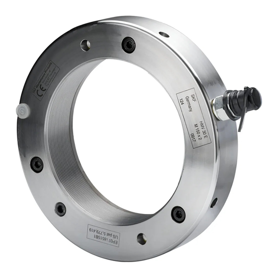
1.1 Principle of operation Figure 1. Parts of the hydraulic nut The hydraulic nut has proved to save considerable effort when mounting or dismounting rolling bearings with tapered bores. It comprises two main components: a steel ring (fig. 1a) with internal thread and a groove in one side face, and an annular piston (fig. 1b) that rests in the groove. The seal (fig. 1c) between the two parts consists of two O-rings. When oil is pumped into the pressure chamber (fig. 1d), the piston is pressed out with a force that normally is sufficient for mounting and dismounting rolling bearings. The outer ring is provided with an unthreaded hole (fig. 1g) to hold a dial indicator (fig. 1h). The measuring tip of the indicator will rest against the shoulder of the piston to indicate axial travel. (Note: The drive-up distance can be used to determine correct mounting; see skf.com/ mount or download the SKF Drive-up Method Program at skf.com. Alternatively download the SKF Drive-up Method app on the App Store or on Google Play™). ® Two threaded holes are provided in the steel ring for attachment of the hose from the pump: one in the side face (fig. 1e), and the other in the circumference (fig. 1f). The hole that is not in use must be plugged with a ball plug, which is supplied with the nut. The hole used for the hose connection should be fitted with a 729832 A nipple, included with the hydraulic nut. A spare set of O-rings, a maintenance set, and a tommy bar for tightening the nut are all included as standard accessories. 1.2 Load carrying capacity SKF hydraulic nuts are designed to withstand the pressure normally encountered when rolling bearings are mounted or dismounted. SKF HMV / HMVC... -
Page 8: Operating Instructions
When the bearing is mounted on a sleeve, make sure that the sleeve is straight, that is, with the thread aligned over the slotted part of the sleeve. It is recommended to always use a thread lubricant before applying the nut on the mating thread. Figure 2. Support for a large hydraulic nut To thread the nut onto the shaft or sleeve use the tommy bar provided. This is inserted in one of the four unthreaded holes in the outside cylindrical surface or in one of the two holes on the side surface. Nuts of size HMV(C) 94E and larger have the provision for two eye bolts (DIN 580) to be fitted. One or both of the eye bolts, when properly fitted, can be used to safely lift the nut. The size of the eye bolts is shown in the following table: HMV(C) ..E nut size Eye Bolt Thread Size (DIN 580) 94 - 130 134 - 160 170 - 200 To facilitate the mounting of nuts of size HMV(C) 94E and larger, an arrow is marked on the nut circumference showing the position of the first thread. SKF HMV / HMVC... -
Page 9: How To Generate The Pressure
HMV nut screwed HMV nut for driving the bearing onto an onto the shaft stop nut for driving the bearing onto a adapter sleeve. for driving in a in a withdrawal tapered seating. withdrawal sleeve. sleeve. SKF HMV / HMVC... -
Page 10: Dismounting Of Bearings
Figure 7. Figure 8. HMV nut used to free a withdrawal HMV nut and stop ring in position to sleeve press loose an adapter sleeve 2.5 SKF Drive-up Method for mounting bearings with a tapered bore Traditionally the radial internal clearance reduction has been measured when mounting bearings with a tapered bore. The accuracy of this method is highly dependent on the technician being skilled in the use of feeler gauges applied to the measurement of the clearance reduction. The SKF Drive-up Method considerably improves the reliability and ease in fitting bearings with a tapered bore and can be used for SKF spherical roller bearings, SKF CARB ®... - Page 11 TMCD 1/2R Hydraulic pumps with digital pressure gauge (fig. 9b) 0 - 100 MPa (0 - 15 000 psi) Maximum nut size HMV (C) 54E HMV (C) 92E HMV (C) 200E Pump reference 729124 DU TMJL 100DU TMJL 50DU Step by step mounting procedure Step 1 Ensure that the bearing size is compatible with the HMV(C) E nut size. For example, for bearing 23936 CCK/W33 mounted direct on a shaft, use HMV(C) 36E. Otherwise the pressure corresponding to the starting position must be adjusted. Step 2 Determine whether one or two surfaces slide during mounting. See figures 10 - 13. Step 3 Drive the bearing up to the starting position by applying the correct hydraulic pressure to the HMV(C) E nut. See figure 14. As an alternative, the SKF digital pressure gauge can be screwed directly into the hydraulic SKF HMV / HMVC...
- Page 12 The starting hydraulic pressure (MPa/psi) and axial drive-up (mm) can be found at skf.com/mount or by downloading the SKF Drive-up Method PC Program at skf.com. Alternatively download the SKF Drive-up Method app on the App Store or on Google Play. Figure 10. One sliding surface Figure 11. One sliding surface Figure 12. Two sliding surfaces Figure 13. Two sliding surfaces Zero Starting Final position position position Figure 14. Bearing position SKF HMV / HMVC...
-
Page 13: Maintenance
Figure 15. Pushing the piston out of the ring A spare set of O-rings is also supplied with the nut. Additional replacement rings can be obtained from SKF. 3.2 Replacement parts Description Designation O-rings Nut designation followed by /233983, for example HMV 10/233983 Ball plug 233950 Quick connection nipple 729832 A Maintenance set HMVM 10/29 (nut size 10...29) (threaded pins, copper rings, HMVM 30/69 (nut size 30...69) hexagonal keys) HMVM 70/200 (nut size 70...200) 3.3 Accessories Description Designation Mounting fluid (5 litres) LHMF 300/5 Dial indicators TMCD 5P (parallel dial, 0-5 mm) TMCD 10R (right angle dial, 0-10 mm) TMCD 1/2R (right angle dial, 0 - SKF HMV / HMVC... -
Page 14: Dimensions
4. Dimensions In the following tables dimensions are given for SKF standard hydraulic nuts HMV...E (metric), and HMVC...E (inch) as well as for hydraulic nuts without threads, HMV...E/A101. The nuts can also be made in other sizes, with special threads, or with unthreaded bores. Additional information will be provided on request. 4.1 Hydraulic nuts - HMV...E series Threads HMV 10E - HMV 40E ISO 965/III-1980, tolerance class 6H HMV 41E - HMV 200E ISO 2901-1977, tolerance class 7H Recommended mating threads HMV 10E - HMV 40E ISO 965/III-1980, tolerance class 6g HMV 41E - HMV 200E ISO 2901-1977, tolerance class 7e SKF HMV / HMVC... - Page 15 17,5 HMV 52E Tr 260x4 262 341 356 18 800 19,5 HMV 54E Tr 270x4 272 352 368 19 800 20,5 HMV 56E Tr 280x4 282 363 380 21 100 22,0 HMV 58E Tr 290x4 292 375 390 22 400 22,5 HMV 60E Tr 300x4 302 386 404 23 600 25,5 SKF HMV / HMVC...
- Page 16 87 700 HMV 150E Tr 750x7 752 883 912 95 200 HMV 160E Tr 800x7 802 936 965 103 900 HMV 170E Tr 850x7 852 990 1 020 114 600 HMV 180E Tr 900x7 902 1 043 1 075 124 100 HMV 190E Tr 950x8 952 1 097 1 126 135 700 HMV 200E Tr 1000x8 1 002 1 150 1 180 145 800 SKF HMV / HMVC...
-
Page 17: Hydraulic Nuts - Hmvc
HMVC 34E 6 659 6 5778 8 6.7 9.3 9.6 1.6 0.28 0.24 14.6 18.5 HMVC 36E 7 066 6 9848 8 7.1 9.7 10.1 1.6 0.28 0.24 16.0 20.2 HMVC 38E 7 472 7 3908 8 7.5 10.2 10.6 1.7 0.31 0.28 17.8 23.1 SKF HMV / HMVC... - Page 18 0.63 0.98 161.0 HMVC 170E 33 473 33 2860 3 33.5 39.0 40.2 3.3 0.63 1.02 177.6 HMVC 180E 35 441 35 2540 3 35.5 41.1 42.3 3.4 0.67 1.18 192.4 HMVC 190E 37 410 37 2230 3 37.5 43.2 44.3 3.4 0.67 1.18 210.3 SKF HMV / HMVC...
-
Page 19: Hydraulic Nuts Without Threads
HMV 29E/A101 141,1 5.56 HMV 96E/A101 474,7 18.69 HMV 30E/A101 146,1 5.75 HMV 98E/A101 484,7 19.08 HMV 31E/A101 149,8 5.90 HMV 100E/A101 494,7 19.48 HMV 32E/A101 154,8 6.09 HMV 102E/A101 503,7 19.83 HMV 33E/A101 159,8 6.29 HMV 104E/A101 513,7 20.22 HMV 34E/A101 164,8 6.49 HMV 106E/A101 523,7 20.62 SKF HMV / HMVC... - Page 20 HMV 50E/A101 245,2 9.65 HMV 150E/A101 742,7 29.24 HMV 52E/A101 255,2 10.05 HMV 160E/A101 792,7 31.21 HMV 54E/A101 265,2 10.44 HMV 170E/A101 842,7 33.18 HMV 56E/A101 275,2 10.83 HMV 180E/A101 892,7 35.15 HMV 58E/A101 285,2 11.23 HMV 190E/A101 941,7 37.07 HMV 60E/A101 295,2 11.62 HMV 200E/A101 991,7 39.04 SKF HMV / HMVC...
- Page 21 Notes: SKF HMV / HMVC...
- Page 22 2.2 Comment produire la pression ..................25 2.3 Montage des roulements ....................25 2.4 Démontage des roulements ..................26 2.5 Méthode de l’enfoncement axial SKF pour monter les roulements avec un alésage conique ......................26 3. Entretien ......................29 3.1 En cas de fuites .......................29 3.2 Pièces de rechange ......................29 3.3 Accessoires ........................29 4. Dimensions ......................30 4.1 Écrous hydrauliques - Séries HMV..E ................30 4.2 Écrous hydrauliques - Séries HMVC..E (filetages en pouces).........33 4.3 Écrous hydrauliques sans filetages ................35 Traduction extraite du mode d’emploi d’origine SKF HMV / HMVC...
-
Page 23: Déclaration De Conformité Ce
Déclaration de conformité CE Nous, SKF Maintenance Products Kelvinbaan 16, 3439 MT Nieuwegein Pays-Bas déclarons que les produits suivants: Écrous Hydrauliques séries HMV..E et HMVC..E auxquels se réfèrent cette déclaration, sont conformes aux conditions de la directive Directive Machines 2006/42/EC et sont en conformité avec les normes suivantes : EN-ISO 12100:2010, EN-ISO 4413 Nieuwegein, Pays-Bas Le 1 Août 2013 Sébastien David Responsable Développement de Produits et Responsable Qualité SKF HMV / HMVC... -
Page 24: Recommandations De Sécurité
• S’assurer que l’air a été totalement évacué du système hydraulique, avant de mettre l’équipement sous pression. • Ne pas utiliser l’écrou hydraulique pour d’autres applications que le montage/démontage des roulements. • Utiliser toujours un manomètre. • Afin d’éviter l’expulsion totale de la pièce à démonter il faut toujours placer une pièce en butée (un écrou par exemple). Ne jamais utiliser l’équipement au-dessus de la pression maximale indiquée. • Ne pas dépasser la course maximale autorisée du piston. • Utiliser des lunettes de protection. • Ne jamais faire de modifications sur la pompe. • Utiliser seulement des pièces d’origine. • Utiliser seulement des huiles hydrauliques propres et recommandées (par exemple: SKF LHMF 300, LHDF 900 ou équivalent) • Les écrous hydrauliques doivent être manipulés et transportés conformément aux pratiques et règles de sécurité de travail. • Les anneaux de levage standard ne doivent en aucun cas être directement montés sur l’écrou, car ils pourraient endommager le filetage de l’écrou. • Des boulon(s) à œillet doivent être installés correctement lorsqu’ils sont fournis. • Pour toute incertitude quant à l’utilisation de l’écrou hydraulique veuillez consulter SKF. SKF HMV / HMVC... -
Page 25: Description
Figure 1. Parties de l’écrou hydraulique L’écrou hydraulique a prouvé qu’il permettait une économie d’effort considérable pour le montage ou le démontage des roulements à alésage conique. Il es constitué de deux parties principales : une bague en acier (fig. 1a) avec un filetage interne et une rainure sur une face latérale, ainsi qu’un piston annulaire (fig. 1b) qui se déplace dans la rainure. L’étanchéité (fig. 1c) entre les deux parties est assurée par deux joints toriques. Lorsque l’huile est injectée dans la chambre de pression (fig. 1d), le piston se déplace avec une force qui est en général suffisante pour le montage et le démontage des roulements. La bague extérieure est munie d’un orifice non fileté (fig. 1g) qui permet de fixer un comparateur à cadran (fig. 1h). La tige de mesure de l’indicateur reposera contre l’épaulement du piston pour signaler la course axiale. (Remarque : La distance de course peut être utilisée pour déterminer si le montage a été réalisé correctement ; consultez le site skf.com/mount ou téléchargez la méthode par enfoncement axial SKF sur le site skf.com. Vous pouvez également télécharger l’app de cette méthode sur l’App Store ou sur Google Play™). ® Deux orifices filetés sont disposés dans la bague en acier pour fixer la pompe : l’un sur la face latérale (fig. 1e) et l’autre sur la génératrice extérieure (fig. 1f). L’orifice non utilisé doit être obturé à l’aide d’un bouchon, fourni avec l’écrou. L’orifice utilisé pour le raccordement du tuyau doit être muni d’un mamelon 729832 A, fourni avec l’écrou hydraulique. Un jeu de joints toriques de rechange, un kit de maintenance et une broche de serrage de l’écrou sont fournis comme accessoires standard. 1.2 Capacité de levage de charges Les écrous hydrauliques SKF sont conçus pour supporter la pression normale lors du montage et démontage des roulements. SKF HMV / HMVC... -
Page 26: Instructions De Fonctionnement
Figure 2. Support d’un grand écrou hydraulique. Pour fileter l’écrou sur l’axe ou le manchon, utilisez la broche fournie. Elle est insérée dans l’un des quatre orifices non filetés sur la surface cylindrique extérieure ou sur l’un des deux trous de la surface latérale. Les écrous de taille HMV(C)94E et plus grands peuvent accueillir deux boulons à œil (DIN 580). Un ou les deux boulons à oeil, lorsqu’ils sont correctement placés, peuvent être utilisés pour soulever l’écrou en toute sécurité. La taille des boulons à œil est illustrée dans le tableau suivant: HMV(C) ..taille de l’écrou Taille du Filetage du Boulon à Œil (DIN 580) 94 - 130 134 - 160 170 - 200 Pour faciliter le montage des écrous de taille HMV(C) 94E et supérieurs, une flèche est indiquée sur la circonférence de l’écrou pour indiquer la position du premier filet. SKF HMV / HMVC... -
Page 27: Comment Produire La Pression
Écrou HMV pour monter le roulement l’axe pour monter à à butée spéciale monter le roulement pour monter à l’aide sur un manchon de l’aide d’un manchon sur un portée d’un manchon démontage de démontage conique serrage SKF HMV / HMVC... -
Page 28: Démontage Des Roulements
HMV non utilisé pour retirer un Écrou HMV et bague de butée en position manchon de démontage pour démonter un manchon de serrage 2.5 Méthode de l’enfoncement axial SKF pour monter les roulements avec un alésage conique La réduction du jeu interne radial est généralement mesurée lors du montage de roulements avec un alésage conique. La précision de cette méthode dépend en grande mesure de l’habilité du technicien à utiliser les jeux de cales pour mesurer la réduction du jeu. La Méthode de l’enfoncement axial SKF améliore considérablement la fiabilité et... - Page 29 TMCD 1/2R Pompes hydrauliques à manomètre numérique (fig. 9b) 0-100 MPa Taille maximale de l’écrou HMV (C) 54E HMV (C) 92E HMV (C) 200E Référence de la pompe 729124 DU TMJL 100DU TMJL 50DU Procédure de montage pas à pas Etape 1 Vérifiez que la taille du roulement est compatible avec la taille de l’écrou HMV(C) E. A titre d’exemple, utiliser l’écrou HMV(C) 36E pour monter le roulement 23936 CCK/W33 directement sur une portée conique d’arbre. Dans le cas contraire, la pression correspondant à la position de départ doit être réglée. Etape 2 Déterminez si une ou deux surfaces glissent pendant le montage. Voir figures 10 - 13. Etape 3 Faites monter le roulement vers la position de départ en appliquant la pression hydraulique correcte vers l’écrou HMV(C) E. Voir figure 14. SKF HMV / HMVC...
- Page 30 Figure 10. Une surface de glissement Figure 11. Une surface de glissement Figure 12. Deux surfaces de glissement Figure 13. Deux surfaces de glissement Zéro Démarrage Final position position position Figure 14. Position de roulement SKF HMV / HMVC...
-
Page 31: Entretien
Figure 15. Pushing the piston out of the ring Vous pouvez au besoin utiliser de la graisse pour maintenir les nouveaux joints toriques en place pendant l’opération de remplacement. Un jeu de joints toriques de rechange est aussi fourni avec l’écrou. Des bagues de rechange supplémentaires peuvent au besoin vous être fournies par SKF. 3.2 Pièces de rechange Description Désignation Joints toriques Référence de l’écrou suivie de /233983, par exemple HMV 10/233983 Raccord cylindrique 233950 Raccord de connexion rapide 729832 A Kit d’entretien HMVM 10/29 (nut size 10...29) (goupilles filetées, bagues en HMVM 30/69 (nut size 30...69) cuivre, clés hexagonales) HMVM 70/200 (nut size 70...200) 3.3 Accessoires Description Désignation Liquide de montage (5 litres) LHMF 300/5 Comparateurs à cadran TMCD 5P (comparateur parallèle, 0 - 5 mm) TMCD 10R (comparateur à angle droit, 0 - 10 mm) TMCD 1/2R (comparateur à angle droit, 0 - in) SKF HMV / HMVC... -
Page 32: Dimensions
4. Dimensions Les dimensions apparaissant dans les tableaux suivants correspondent aux écrous hydrauliques standard de SKF HMV...E (métriques) et HMVC..E (pouces) ainsi que pour les écrous hydrauliques sans filetages, HMV ...E/A101. Les écrous peuvent avoir d’autres tailles, avec des filetages spéciaux, ou sans alésages non filetés. Vous pouvez obtenir des informations supplémentaires sur simple demande. 4.1 Écrous hydrauliques - Séries HMV..E Filetages HMV 10E - HMV 40E ISO 965/III-1980, classe de tolérance 6H HMV 41E - HMV 200E ISO 2901-1977, classe de tolérance 7H Filetages correspondants recommandés HMV 10E - HMV 40E ISO 965/III-1980, classe de tolérance 6g HMV 41E - HMV 200E ISO 2901-1977, classe de tolérance 7e SKF HMV / HMVC... - Page 33 17,5 HMV 52E Tr 260x4 262 341 356 18 800 19,5 HMV 54E Tr 270x4 272 352 368 19 800 20,5 HMV 56E Tr 280x4 282 363 380 21 100 22,0 HMV 58E Tr 290x4 292 375 390 22 400 22,5 HMV 60E Tr 300x4 302 386 404 23 600 25,5 SKF HMV / HMVC...
- Page 34 87 700 HMV 150E Tr 750x7 752 883 912 95 200 HMV 160E Tr 800x7 802 936 965 103 900 HMV 170E Tr 850x7 852 990 1 020 114 600 HMV 180E Tr 900x7 902 1 043 1 075 124 100 HMV 190E Tr 950x8 952 1 097 1 126 135 700 HMV 200E Tr 1000x8 1 002 1 150 1 180 145 800 SKF HMV / HMVC...
-
Page 35: Écrous Hydrauliques - Séries Hmvc
HMVC 34E 6 659 6 5778 8 6.7 9.3 9.6 1.6 0.28 0.24 14.6 18.5 HMVC 36E 7 066 6 9848 8 7.1 9.7 10.1 1.6 0.28 0.24 16.0 20.2 HMVC 38E 7 472 7 3908 8 7.5 10.2 10.6 1.7 0.31 0.28 17.8 23.1 SKF HMV / HMVC... - Page 36 0.63 0.98 161.0 HMVC 170E 33 473 33 2860 3 33.5 39.0 40.2 3.3 0.63 1.02 177.6 HMVC 180E 35 441 35 2540 3 35.5 41.1 42.3 3.4 0.67 1.18 192.4 HMVC 190E 37 410 37 2230 3 37.5 43.2 44.3 3.4 0.67 1.18 210.3 SKF HMV / HMVC...
-
Page 37: Écrous Hydrauliques Sans Filetages
HMV 29E/A101 141,1 5.56 HMV 96E/A101 474,7 18.69 HMV 30E/A101 146,1 5.75 HMV 98E/A101 484,7 19.08 HMV 31E/A101 149,8 5.90 HMV 100E/A101 494,7 19.48 HMV 32E/A101 154,8 6.09 HMV 102E/A101 503,7 19.83 HMV 33E/A101 159,8 6.29 HMV 104E/A101 513,7 20.22 HMV 34E/A101 164,8 6.49 HMV 106E/A101 523,7 20.62 SKF HMV / HMVC... - Page 38 HMV 50E/A101 245,2 9.65 HMV 150E/A101 742,7 29.24 HMV 52E/A101 255,2 10.05 HMV 160E/A101 792,7 31.21 HMV 54E/A101 265,2 10.44 HMV 170E/A101 842,7 33.18 HMV 56E/A101 275,2 10.83 HMV 180E/A101 892,7 35.15 HMV 58E/A101 285,2 11.23 HMV 190E/A101 941,7 37.07 HMV 60E/A101 295,2 11.62 HMV 200E/A101 991,7 39.04 SKF HMV / HMVC...
- Page 39 SKF HMV / HMVC...
- Page 40 1.2 Belastbarkeit ........................41 2. Betriebsanleitung....................42 2.1 Aufschrauben der Hydraulikmutter auf das Gegengewinde ........42 2.2 Ölpumpen .........................43 2.3 Lagereinbau ........................43 2.4 Ausbau von Lagern auf Spann- oder Abziehhülse ............44 2.5 SKF Drive-up Montageverfahren für Lager mit kegeliger Bohrung .......45 3. Instandhaltung ....................48 3.1 Leckagen ..........................48 3.2 Ersatzteile .........................48 3.3 Zubehör ..........................49 4. Produktdaten .....................49 4.1 Hydraulikmuttern - Reihe HMV E ................49 4.2 Hydraulische Muttern - Serie HMVC.E (Gewinde in Inch) .
-
Page 41: Ce Konformitätserklärung
CE Konformitätserklärung Die SKF Maintenance Products Kelvinbaan 16, 3439 MT Nieuwegein in den Niederlanden erklärt hiermit, dass die Geräte: Hydraulikmuttern der reihe HMV und HMVC in Übereinstimmung mit der Richtlinie: EG-Maschinenrichtlinie 2006/42/EC und den Normen: EN-ISO 12100:2010, EN-ISO 4413 konstruiert und hergestellt wurden. Nieuwegein, in den Niederlanden August 2013 Sébastien David Leiter Produktentwicklung und Qualität SKF HMV / HMVC... -
Page 42: Sicherheitshinweise
Beschädigungen, dürfen keinesfalls verwendet werden. • Vor dem Druckaufbau im Gerät muß das Hydrauliksystem vollständig entlüftet werden. • Die Hydraulikmutter niemals für andere Anwendungen verwenden als für den Ein- und Ausbau von Lagern. • Nie ohne Manometer arbeiten. • Wenn sich das zu demontierende Bauteil oder Werkzeug gelöst hat, besteht die Gefahr, dass es schlagartig von seinem Sitz herunterschießt. Daher Bauteil/Werkzeug immer sichern, beispielsweise mit einer Sicherungsmutter. • Der maximal zulässige Kolbenhub darf nicht überschritten werden. • Immer Schutzbrille tragen. • Auf keinen Fall Veränderungen am Gerät vornehmen. • Nur Original-Ersatzteile verwenden. • Nur saubere Drucköle nach SKF Empfehlung verwenden (z.B. SKF LHMF 300, SKF LHDF 900, o.ä.). • Der Umgang mit Muttern sollte den Arbeitssicherheits- und örtlichen Vorschriften entsprechen. • Bitte keine Hebeseile aus Stahl direkt an der Mutter befestigen, da diese die Gewinde der Mutter beschädigen könnten. • Ringschrauben (wo verwendet) sind sorgfältig anzupassen. • Wenn Sie Fragen zur Benutzung der Hydraulikmutter haben oder Unsicherheit vorliegt, wenden Sie sich bitte an SKF. SKF HMV / HMVC... -
Page 43: Beschreibung
1. Beschreibung 1.1 Funktionsprinzip Bild 1. Aufbau einer Hydraulikmutter Hydraulikmutter erleichtern erheblich die Montage und Demontage von Wälzlagern mit kegeliger Lagerbohrung. Sie bestehen im wesentlichen aus zwei Teilen: einem Ringkörper mit Innengewinde und einer Ringnut in einer Seitenfläche (1a), in die der Ringkolben (1b) eingesetzt ist. Zwei O-Ringe (1c) dienen als Abdichtung zwischen Ringkörper und Ringkolben. Wenn Öl in die Druckkammer (1d) gepumpt wird, reicht die beim Herauspressen des Kolbens erzeugte Kraft zum Einbau und Ausbau von Wälzlagern aus. Für den Anschluss der Ölleitung befinden sich im Ringkörper zwei Gewindebohrungen, eine in der Seitenfläche (1e) und eine im zylindrischen Mantel (1f). Die jeweils nicht benötigte Gewindebohrung wird durch einen Verschlussnippel mit Kugel verschlossen, der zusammen mit der Hydraulikmutter geliefert wird. Der Ringkörper ist außerdem mit einer gewindelosen Durchgangsbohrung (1h) versehen, in die eine Messuhr eingesetzt werden kann. Der Messbolzen der Uhr liegt gegen einen Ansatz am Ringkolben an und erlaubt so die genaue Messung der axialen Verschiebung des Ringkolbens und damit des Lagers. (Hinweis: Über den Aufschiebeweg lässt sich der korrekte Einbau ermitteln; Infos unter skf.com/mount oder durch Herunterladen des Programms zum SKF Drive-up Verfahren auf skf.com. Alternativ können Sie sich auch die App zum SKF Drive-up Verfahren im App Store oder über Google Play™ herunterladen). ® Alle Hydraulikmuttern sind zum einfachen Anschluss an die Ölpumpen mit dem Anschlussnippel 729832 A für Schnellkupplungen ausgerüstet. Außerdem liegt allen Muttern ein Revervesatz von Dichtringen, ein Wartungssatz und ein Steckgriff zum Drehen der Mutter auf dem Gegengewinde bei. 1.2 Belastbarkeit Die SKF Hydraulikmuttern sind für die beim Einbau und Ausbau von Wälzlagern üblicherweise auftretenden Kräfte ausgelegt. SKF HMV / HMVC... -
Page 44: Betriebsanleitung
Bei der Montage von Lagern auf Spann- oder Abziehhülsen ist darauf zu achten, dass die Stirnseiten der Hülsen planparallel ausgerichtet sind damit die Gewindegänge fluchten. Außerdem empfiehlt es sich, vor dem Aufschrauben der Hydraulikmutter das Gegengewinde mit einer Molybdändisulfitpaste oder einer ähnlichen Montagepaste zu bestreichen. Bild 2. Abstützung einer großen Hydraulikmutter Das Aufschrauben der Mutter auf das Wellen- oder Hülsengewinde erleichtert der mitgelieferte Steckgriff. Hierzu sind am Umfang des Ringkörpers der Mutter vier und in der Seitenfläche zwei gewindelose Sackbohrungen angebracht, in die der Steckgriff eingesetzt werden kann. Die Hydraulikmuttern ab der Größe HMV(C) 94 E sind zusätzlich mit zwei Gewindebohrungen für Ringschrauben nach DIN 580:1972 versehen. Dies ermöglicht die Verwendung von Anschlagmitteln in Verbindung mit einem Kran, was das Handhaben der Hydraulikmuttern wesentlich sicherer und leichter macht. Die Größen der Gewindebohrungen sind in der nachfolgenden Tabelle aufgeführt: HMV(C) ..E Mutterngröße Ringschrauben- Gewinde (DIN 580) 94 - 130 134 - 160 170 - 200 SKF HMV / HMVC... -
Page 45: Ölpumpen
Aufstellung entnommen werden. HMV(C) 10E - HMV(C) 54E 729124/TMJL 50/TMJL 100/728619E HMV(C) 56E - HMV(C) 92E TMJL 50/TMJL 100/728619E HMV(C) 94E - HMV(C) 200E TMJL 50/728619E Bei Anwendung des SKF Montageverfahrens (SKF Drive-up Method): HMV(C) 10E ... 54E 729124 DU/TMJL 50DU/TMJL 100DU HMV(C) 56E ... 92E TMJL 50DU/TMJL 100DU HMV(C) 94E ... 200E TMJL 50DU Hinweis: Durch das Nachsetzzeichen DU gekennzeichnete Ölpumpen sind mit dem Digital- Manometer THGD 100 (0 - 100 MPa) ausgerüstet. Als Druckmedien eignen sich normale Maschinenöle mit einer Viskosität von etwa 300 mm /s bei Betriebstemperatur, zum Beispiel die SKF Montageflüssigkeit LHMF 300. Vor Beginn der Betätigung der Mutter ist sicherzustellen, dass sich keine Luft mehr im “hydraulischen System” befindet. Hierzu empfiehlt es sich, die Hydraulikmutter so anzuordnen, dass sich die nicht benötigte Gewindebohrung für den Ölanschluss an der höchsten Stelle befindet. Nach Öffnen der Verschlussschraube mit Kugel ist so lange Öl in die Mutter zu pumpen bis blasenfreies Öl austritt. Danach ist die Verschlussschraube mit Kugel wieder zu schließen und das System betriebsbereit. 2.3 Lagereinbau Die Hydraulikmutter (mit dem Ringkolben in Ausgangsstellung) ist vorsichtig auf das Wellen- bzw. Hülsengewinde aufzuschrauben und ist gegen den Lagerinnenring (Bilder 3 und 4), die Abziehhülse (Bild 5) oder eine spezielle Wellenmutter (Bild 6) bzw. gegen eine am Wellenende angeschraubte Endscheibe abzustützten. Es ist darauf zu achten, dass das Mutterngewinde möglichst über seine gesamte Länge das Gegengewinde abdeckt. Der Mindestwert von 80% sollte jedoch nicht unterschritten werden. Kann auch dieser Wert nicht eingehalten werden, ist eine zusätzliche Abstützung der Hydraulikmutter erforderlich. SKF HMV / HMVC... -
Page 46: Ausbau Von Lagern Auf Spann- Oder Abziehhülse
7) oder einen speziellen zweiteiligen Ring (Bild 8) abgestützt. Durch Einpressen von Öl in die Hydraulikmutter wird der Ringkolben herausgedrückt und die Abziehhülse aus der Lagerbohrung herausgezogen bzw. die Spannhülse unter dem Lager durchgeschoben. Ausbau Bild 8. Bild 7. Ausbau eines Lager auf Spannhülse mit Herausziehen einer Abziehhülse aus einer auf dem Hülsengewinde montierten einer kegeligen Lagerbohrung Hydraulikmutter, die gegen einen Anschlag auf der Welle abgestützt ist. SKF HMV / HMVC... -
Page 47: Skf Drive-Up Montageverfahren Für Lager Mit Kegeliger Bohrung
2.5 SKF Drive-up Montageverfahren für Lager mit kegeliger Bohrung Bei Lagern mit kegeliger Bohrung wurde ursprünglich die Lagerluftverminderung als Maß für die Festigkeit der Passung herangezogen. Dieses Montageverfahren erforderte jedoch gut ausgebildete Servicetechniker mit viel Geschick bei der Messung der Lagerluft mit Fühllehren. Das SKF Drive-up Montageverfahren erhöht entscheidend die Zuverlässigkeit und erleichtert erheblich den Einbau von Lagern mit kegeliger Bohrung. Es basiert auf der axialen Verschiebung des Lagers gegenüber dem kegeligen Lagersitz und wurde für den Einbau von Pendelrollenlagern, CARB ® Toroidal-Rollenlager und einiger Pendelkugellager entwickelt. Für jedes einzelne Lager erarbeitete Richtwerte für den erforderlichen Druck in der Hydraulikmutter machen die sichere Bestimmung der Ausgangslage möglich, von der aus die axiale Verschiebung zu messen ist. Um das SKF Drive-up Montageverfahren anwenden zu können, sind ein auf die Montagebedingungen abgestimmtes Digital-Manometer und eine Messuhr (Bild 9) erforderlich. Durch das Nachsetzzeichen DU gekennzeichnete SKF Ölpumpen sind mit einem Digital-Manometer für Drücke von 0 - 100 MPa ausgerüstet. Bild 9. Messuhr mit Ölpumpe SKF HMV / HMVC... - Page 48 Hydraulikpumpen mit digitalem Manometer ( Bild 9b ) 0-100 MPa Ölpumpen für Muttern bis zur Größe HMV (C) 54E HMV (C) 92E HMV (C) 200E Angaben zur Pumpe 729124 DU TMJL 100DU TMJL 50DU Die Vorgehensweise Schritt 1 Vergewissern Sie sich, dass die Lagergröße mit der HMV(C)E Mutterngröße kompatibel ist. Beispiel: Verwenden Sie HMV(C) 36E für das auf einer Welle montierte Lager 23936 CCK/W33. Anderfalls muss der der Anfangsposition entsprechende Druck angepasst werden. Schritt 2 Bestimmen Sie, ob während der Montage eine oder zwei Flächen gleiten sollen. Siehe Bild 10 - 13. Schritt 3 Fahren Sie das Lager auf die Anfangsposition hoch, indem Sie auf die HMV(C)E-Mutter den korrekten hydraulischen Druck einwirken lassen. Siehe Bild 14. Alternativ kann die SKF digitale Druckanzeige direkt auf die hydraulische Mutter geschraubt werden. Fahren Sie das Lager auf dem Kegel hoch, bis der gewünschte Abstand erreicht ist. Verfolgen Sie das axiale Hochfahren mit Hilfe eines Feinzeigers. Den anfänglichen Hydraulikdruck (MPa/psi) sowie die axiale Verschiebung (mm) finden Sie auf skf.com/mount oder durch Herunterladen des PC-Programms zum SKF Drive-up Verfahren auf skf.com. Alternativ können Sie sich auch die App zum SKF Drive-up Verfahren im App Store oder über Google Play) herunterladen. SKF HMV / HMVC...
- Page 49 Bild 10. Eine Gleitfläche Bild 11. Eine Gleitfläche Bild 12. Zwei Gleitflächen Bild 13. Zwei Gleitflächen Null- Start- End- position position position Bild 14. Einbaupositionen SKF HMV / HMVC...
-
Page 50: Instandhaltung
Hilfsbohrungen angebracht. Mit Hilfe von Stiften, die zum Lieferumfang gehören, kann über diese Bohrungen der Ringkolben aus dem Ringkörper herausgedrückt werden Bild 15. Herausdrücken des Ringkolbens (Bild 15). Zusätzliche Ersatzdichtringe sind von uns erhältlich. Bei ihrer Bestellung ist mit der Bezeichnung der Hydraulikmutter, für die die Dichtringe benötigt werden, das Nachsetzzeichen /233983 anzugeben, z. B. HMV 10 E/233983. 3.2 Ersatzteile Beschreibung Bezeichnung Dichtringe Mutternbezeichnung + Nachsetzzeichen / 233983, zum Beispiel HMV 10/233983 Verschlussschraube mit Kugel 233950 Schnellkupplung 729832 A Wartungssatz HMVM 10/29 (für Muttern der Größe 10...29) (Gewindestiften, Kupferringen, HMVM 30/69 (für Muttern der Größe 30...69) Sechskantschlüssel)) HMVM 70/200 (für Muttern der Größe 70...200) SKF HMV / HMVC... -
Page 51: Zubehör
3.3 Zubehör Beschreibung Bezeichnung Montageflüssigkeit, 5 Liter LHMF 300/5 Messuhr TMCD 5P ((rückwärtigem Messbolzen, 0-5 mm) TMCD 10R (seitlichem Messbolzen, 0-10 mm) TMCD 1/2R (seitlichem Messbolzen, 0 - in) 4. Produktdaten In den nachfolgenden Tabellen sind die Produktdaten der SKF Hydraulikmuttern der Standardreihe HMV E mit metrischem Gewinde, der Reihe HMVC... E mit Zollgewinde, und der Reihe HMV E/A101 ohne Gewinde aufgeführt. Weitergehende Informationen erhalten Sie auf Anfrage. 4.1 Hydraulikmuttern - Reihe HMV E Mutterngewinde HMV 10E - HMV 40E ISO 965/III-1980, Toleranzklasse 6H HMV 41E - HMV 200E ISO 2901-1977, Toleranzklasse 7H Empfohlene Einschraubgewinde HMV 10E - HMV 40E ISO 965/III-1980, Toleranzklasse 6g HMV 41E - HMV 200E ISO 2901-1977, Toleranzklasse 7e SKF HMV / HMVC... - Page 52 17,5 HMV 52E Tr 260x4 262 341 356 18 800 19,5 HMV 54E Tr 270x4 272 352 368 19 800 20,5 HMV 56E Tr 280x4 282 363 380 21 100 22,0 HMV 58E Tr 290x4 292 375 390 22 400 22,5 HMV 60E Tr 300x4 302 386 404 23 600 25,5 SKF HMV / HMVC...
- Page 53 87 700 HMV 150E Tr 750x7 752 883 912 95 200 HMV 160E Tr 800x7 802 936 965 103 900 HMV 170E Tr 850x7 852 990 1 020 114 600 HMV 180E Tr 900x7 902 1 043 1 075 124 100 HMV 190E Tr 950x8 952 1 097 1 126 135 700 HMV 200E Tr 1000x8 1 002 1 150 1 180 145 800 SKF HMV / HMVC...
-
Page 54: Hydraulische Muttern - Serie Hmvc.e (Gewinde In Inch)
HMVC 34E 6 659 6 5778 8 6.7 9.3 9.6 1.6 0.28 0.24 14.6 18.5 HMVC 36E 7 066 6 9848 8 7.1 9.7 10.1 1.6 0.28 0.24 16.0 20.2 HMVC 38E 7 472 7 3908 8 7.5 10.2 10.6 1.7 0.31 0.28 17.8 23.1 SKF HMV / HMVC... - Page 55 0.63 0.98 161.0 HMVC 170E 33 473 33 2860 3 33.5 39.0 40.2 3.3 0.63 1.02 177.6 HMVC 180E 35 441 35 2540 3 35.5 41.1 42.3 3.4 0.67 1.18 192.4 HMVC 190E 37 410 37 2230 3 37.5 43.2 44.3 3.4 0.67 1.18 210.3 SKF HMV / HMVC...
-
Page 56: Hydraulikmuttern Ohne Gewinde
HMV 29E/A101 141,1 5.56 HMV 96E/A101 474,7 18.69 HMV 30E/A101 146,1 5.75 HMV 98E/A101 484,7 19.08 HMV 31E/A101 149,8 5.90 HMV 100E/A101 494,7 19.48 HMV 32E/A101 154,8 6.09 HMV 102E/A101 503,7 19.83 HMV 33E/A101 159,8 6.29 HMV 104E/A101 513,7 20.22 HMV 34E/A101 164,8 6.49 HMV 106E/A101 523,7 20.62 SKF HMV / HMVC... - Page 57 HMV 50E/A101 245,2 9.65 HMV 150E/A101 742,7 29.24 HMV 52E/A101 255,2 10.05 HMV 160E/A101 792,7 31.21 HMV 54E/A101 265,2 10.44 HMV 170E/A101 842,7 33.18 HMV 56E/A101 275,2 10.83 HMV 180E/A101 892,7 35.15 HMV 58E/A101 285,2 11.23 HMV 190E/A101 941,7 37.07 HMV 60E/A101 295,2 11.62 HMV 200E/A101 991,7 39.04 SKF HMV / HMVC...
- Page 58 2.2 Cómo generar la presión ....................61 2.3 Montaje de rodamientos ....................61 2.4 Desmontaje de rodamientos ..................62 2.5 Método del Calado Axial SKF para el montaje de rodamientos con agujero cónico ..........................62 3. Mantimiento ......................65 3.1 En caso de fuga.......................65 3.2 Piezas de repuesto ......................65 3.3 Accesorios ........................65 4. Dimensiones ......................66 4.1 Tuercas hidráulicas - serie HMV...E ................66 4.2 Tuercas hidráulicas - serie HMVC...E (rosca en pulgadas) ........69 4.3 Tuercas hidráulicas sin rosca ..................71 Traducción de las instrucciones originales SKF HMV / HMVC...
-
Page 59: Declaración De Conformidad Ce
Declaración de Conformidad CE SKF Maintenance Products Kelvinbaan 16, 3439 MT Nieuwegein Países Bajos declaramos que los siguientes productos: Tuercas Hidráulicas Serie HMV y HMVC a los que se refiere esta declaración, han sido diseñados y fabricados de acuerdo con la siguiente directiva: Directiva 2006/42/E (Máquinas) y están clasificados de acuerdo con las siguientes normas: EN-ISO 12100:2010, EN-ISO 4413 Nieuwegein, Países Bajos Agosto de 2013 Sébastien David Jefe de Desarrollo de producto y Calidad SKF HMV / HMVC... -
Page 60: Recomendaciones De Seguridad
• Asegúrese de que todo el aire ha sido eliminado del sistema hidráulico antes de poner el equipo bajo presión. • No use la tuerca hidráulica para trabajos que no sean de montaje y desmontaje de rodamientos. • Use siempre un manómetro. • Téngase siempre en cuenta que la pieza de trabajo/herramienta puede salir súbitamente proyectada al estar sometida a alta presión (use una tuerca tope o de retención). • No supere el máximo desplazamiento permitido del pistón. • Use guantes protectores. • No modifique nunca el equipo. • Use sólamente recambios y piezas originales. • Use sólamente aceites hidráulicos recomendados y límpios (por ejemplo, SKF LHMF 300, LHDF 900 o similar). • Se debe elevar las tuercas y manejarlas según las prácticas de seguridad laboral y las normativas locales. • Los cables de acero de elevación no deberían tocar las tuercas, ya que podrían dañar las roscas. • Los pernos de armella, si los hubiera, deberán estar correctamente instalados. • En caso de duda en relación con el uso de la bomba hidráulica, contacte con SKF. SKF HMV / HMVC... -
Page 61: Descripción
1.1 Principio de funcionamiento Figura 1. Componentes de la tuerca hidráulica La tuerca hidráulica ha demostrado ahorrar un considerable esfuerzo a la hora de montar o desmontar rodamientos con agujero cónico. La tuerca consta de dos componentes principales: un anillo de acero (fig. 1a) con rosca interna y una ranura en una de sus caras, y un pistón anular (fig. 1b) que descansa en la ranura. El sellado (fig. 1c) entre ambas piezas se realiza con dos juntas tóricas. Cuando se bombea aceite al interior de la cámara de presión (fig. 1d), el pistón es empujado normalmente con fuerza suficiente para montar y desmontar los rodamientos. El anillo exterior está provisto de un orificio sin rosca (fig. 1g) para montar un comparador (fig. 1h). La punta del comparador apoyará sobre el reborde del pistón para indicar el desplazamiento axial. (Nota: La distancia de calado se puede utilizar para determinar el montaje correcto; consulte en skf.com/mount o descargue el Programa para el método de calado de rodamientos SKF Drive-up ingresando en skf.com. Alternativamente, descargue la aplicación del método SKF Drive-up en App Store o en Google Play™). ® El anillo de acero presenta dos orificios roscados para el acoplamiento del tubo de la bomba: uno en la cara (fig. 1e) y el otro en el perímetro (fig. 1f). El orificio no utilizado debe cerrarse con un tapón esférico, suministrado con la tuerca. El orificio utilizado para la conexión del tubo debe estar provisto de un manguito 729832 A, incluido con la tuerca hidráulica. También se incluyen como accesorios estándar un juego de juntas tóricas de repuesto, un kit de mantenimiento y una barra para apretar la tuerca. 1.2 Capacidad de carga Las tuercas hidráulicas SKF han sido diseñadas para resistir la presión que se produce normalmente al montar o desmontar los cojinetes de rodillos. SKF HMV / HMVC... -
Page 62: Instrucciones De Utilización
Figura 2. Apoyo de las tuercas hidráulicas grandes Para enroscar la tuerca en el eje o manguito, utilice la barra suministrada. Esta se introduce en uno de los cuatro orificios sin rosca del perímetro exterior o en uno de los dos orificios del lateral. Las tuercas de tamaño HMV(C) 94E y superior permiten la instalación de dos cáncamos (DIN 580). Se puede utilizar uno o los cáncamos, si están correctamente instalados, para levantar la tuerca de forma segura. El tamaño de los cáncamos se indica en la siguiente tabla: Tamaño de la tuerca HMV(C) ..E Tamaño de la rosca del cáncamo (DIN 580) 94 - 130 134 - 160 170 - 200 Para facilitar el montaje de las tuercas de tamaño HMV(C) 94E y superior, el perímetro de la tuerca lleva marcada una flecha que indica la posición del inicio de la rosca. SKF HMV / HMVC... -
Page 63: Cómo Generar La Presión
SKF HMV / HMVC... -
Page 64: Desmontaje De Rodamientos
Tuerca HMV y anillo de retención en posición Tuerca HMV utilizada para liberar un para soltar un manguito de montaje manguito de desmontaje 2.5 Método del Calado Axial SKF para el montaje de rodamientos con agujero cónico Tradicionalmente se medía la reducción del juego radial interno al montar rodamientos con agujero cónico. La precisión de este método depende en gran medida de la habilidad del técnico a la hora de utilizar las galgas para la medición de la reducción de juego. - Page 65 TMCD 1/2R Bombas hidráulicas con manómetro digital (fig. 9b) 0-100 MPa Tamaño máximo de la tuerca HMV (C) 54E HMV (C) 92E HMV (C) 200E Référence de la pompe 729124 DU TMJL 100DU TMJL 50DU Procedimiento de montaje paso a paso: Paso 1 Compruebe que el tamaño del rodamiento sea compatible con el tamaño de la tuerca HMV(C) E. Por ejemplo, para el rodamiento 23936 CCK/W33 montado directamente sobre un eje, utilice la HMV(C) 36E. De lo contrario, será necesario ajustar la presión correspondiente a la posición inicial. Paso 2 Determine si existe una o dos superficies deslizantes durante el montaje. Véanse las figuras 10 - 13. Paso 3 Levante el cojinete hasta la posición inicial aplicando la presión hidráulica correcta a la SKF HMV / HMVC...
- Page 66 SKF Drive-up en skf.com. Alternativamente, descargue la aplicación del método SKF Drive-up en App Store o en Google Play. Figura 10. Una superficie deslizante Figura 11. Una superficie deslizante Figura 12. Dos superficies deslizantes Figura 13. Dos superficies deslizantes Zero Starting Final position position position Figura 14. Posición del rodamiento SKF HMV / HMVC...
-
Page 67: Mantimiento
Figura 15. Expulsión del pistón fuera del anillo posición. Si es necesario, puede utilizar grasa para mantener las juntas tóricas nuevas en la posición correcta durante el montaje.Se incluye un juego de juntas tóricas de repuesto con la tuerca. Puede solicitar juntas tóricas de repuesto adicionales a SKF. 3.2 Piezas de repuesto Descripción Designación Juntas tóricas Designación de la tuerca seguida de /233983, por ejemplo HMV 10/233983 Tapón esférico 233950 Manguito de conexión rápida 729832 A Kit de mantenimiento HMVM 10/29 (tamaño de la tuerca 10...29) (pasadores roscados, anillos HMVM 30/69 (tamaño de la tuerca 30...69) de cobre, llaves hexagonales) HMVM 70/200 (tamaño de la tuerca 70...200) 3.3 Accesorios Descripción Designación Fluido de montaje (5 litros) LHMF 300/5 Comparadores TMCD 5P (comparador paralelo, 0-5 mm) TMCD 10R (comparador de ángulo recto, 0-10 mm) TMCD 1/2R (comparador de ángulo recto, 0 - pulgadas) SKF HMV / HMVC... -
Page 68: Dimensiones
4. Dimensiones En las siguientes tablas figuran las dimensiones para las tuercas hidráulicas SKF estándar HMV...E (métricas) y HMVC...E (pulgadas), así como para las tuercas hidráulicas sin rosca HMV...E/A101. Las tuercas también se pueden fabricar en otros tamaños, con roscas especiales o con orificios sin rosca. Se ofrecerá información adicional si así se solicita. 4.1 Tuercas hidráulicas - serie HMV...E Rosca HMV 10E - HMV 40E ISO 965/III-1980, clase de tolerancia 6H HMV 41E - HMV 200E ISO 2901-1977, clase de tolerancia 7H Rosca correspondiente recomendada HMV 10E - HMV 40E ISO 965/III-1980, clase de tolerancia 6g HMV 41E - HMV 200E ISO 2901-1977, clase de tolerancia 7e SKF HMV / HMVC... - Page 69 17,5 HMV 52E Tr 260x4 262 341 356 18 800 19,5 HMV 54E Tr 270x4 272 352 368 19 800 20,5 HMV 56E Tr 280x4 282 363 380 21 100 22,0 HMV 58E Tr 290x4 292 375 390 22 400 22,5 HMV 60E Tr 300x4 302 386 404 23 600 25,5 SKF HMV / HMVC...
- Page 70 87 700 HMV 150E Tr 750x7 752 883 912 95 200 HMV 160E Tr 800x7 802 936 965 103 900 HMV 170E Tr 850x7 852 990 1 020 114 600 HMV 180E Tr 900x7 902 1 043 1 075 124 100 HMV 190E Tr 950x8 952 1 097 1 126 135 700 HMV 200E Tr 1000x8 1 002 1 150 1 180 145 800 SKF HMV / HMVC...
-
Page 71: Tuercas Hidráulicas - Serie Hmvc
HMVC 34E 6 659 6 5778 8 6.7 9.3 9.6 1.6 0.28 0.24 14.6 18.5 HMVC 36E 7 066 6 9848 8 7.1 9.7 10.1 1.6 0.28 0.24 16.0 20.2 HMVC 38E 7 472 7 3908 8 7.5 10.2 10.6 1.7 0.31 0.28 17.8 23.1 SKF HMV / HMVC... - Page 72 0.63 0.98 161.0 HMVC 170E 33 473 33 2860 3 33.5 39.0 40.2 3.3 0.63 1.02 177.6 HMVC 180E 35 441 35 2540 3 35.5 41.1 42.3 3.4 0.67 1.18 192.4 HMVC 190E 37 410 37 2230 3 37.5 43.2 44.3 3.4 0.67 1.18 210.3 SKF HMV / HMVC...
-
Page 73: Tuercas Hidráulicas Sin Rosca
HMV 29E/A101 141,1 5.56 HMV 96E/A101 474,7 18.69 HMV 30E/A101 146,1 5.75 HMV 98E/A101 484,7 19.08 HMV 31E/A101 149,8 5.90 HMV 100E/A101 494,7 19.48 HMV 32E/A101 154,8 6.09 HMV 102E/A101 503,7 19.83 HMV 33E/A101 159,8 6.29 HMV 104E/A101 513,7 20.22 HMV 34E/A101 164,8 6.49 HMV 106E/A101 523,7 20.62 SKF HMV / HMVC... - Page 74 HMV 50E/A101 245,2 9.65 HMV 150E/A101 742,7 29.24 HMV 52E/A101 255,2 10.05 HMV 160E/A101 792,7 31.21 HMV 54E/A101 265,2 10.44 HMV 170E/A101 842,7 33.18 HMV 56E/A101 275,2 10.83 HMV 180E/A101 892,7 35.15 HMV 58E/A101 285,2 11.23 HMV 190E/A101 941,7 37.07 HMV 60E/A101 295,2 11.62 HMV 200E/A101 991,7 39.04 SKF HMV / HMVC...
- Page 75 Notas: SKF HMV / HMVC...
- Page 76 2.2 Come generare la pressione ..................79 2.3 Montaggio dei cuscinetti ....................79 2.4 Smontaggio dei cuscinetti .....................80 2.5 Metodo SKF Drive-up per montare i cuscinetti con foro conico ......80 3. Manutenzione ....................83 3.1 In caso di perdita ......................83 3.2 Pezzi di ricambio ......................83 3.3 Accessori ...........................83 4. Dimensioni ......................84 4.1 Ghiere idrauliche - HMV...E series ................84 4.2 Ghiere idrauliche - serie HMVC (filettature in pollici) ..........87 4.3 Ghiere idrauliche senza filettatura ................89 Traduzione delle istruzioni originali SKF HMV / HMVC...
-
Page 77: Dichiarazione Di Conformità Ce
Dichiarazione di Conformità CE Noi, SKF Maintenance Products Kelvinbaan 16, 3439 MT Nieuwegein Paesi Bassi dichiariamo con la presente che i seguenti prodotti: Ghiere Idrauliche Serie HMV ed HMVC a cui tale dichiarazione si riferisce, sono conformi alle condizioni della seguente direttiva: Direttiva Macchine 2006/42/EC e sono conformi ai seguenti standard: EN-ISO 12100:2010, EN-ISO 4413 Nieuwegein, Paesi Bassi Agosto 2013 Sébastien David Responsabile Sviluppo Prodotto e Qualità SKF HMV / HMVC... -
Page 78: Precauzioni Di Securezza
Controllare attentamente la ghiera idraulica e tutti gli accessori prima di farne uso. Evitare l’utilizzo anche in caso di modesti danneggiamenti. • Assicurarsi che tutta l’aria sia stata eliminata dal circuito idraulico prima di utilizzare l’attrezzatura. • Non utilizzare la ghiera idraulica per altre applicazioni che non siano il montaggio e lo smontaggio di cuscinetti. • Utilizzare sempre un manometro. • È sempre necessario prevedere un sistema di arresto (es: una ghiera di bloccaggio) per evitare che il particolare meccanico venga proiettato violentemente verso l’esterno al momento del distacco • Non superare lo spostamento massimo consentito del pistone. • Indossare occhiali protettivi. • Non apportare modifiche all’attrezzatura. • Utillizzare esclusivamente ricambi originali. • Utilizzare solamente oli idraulici puliti (es. SKF LHMF 300, LHDF 900 o similari). • Le ghiere idrauliche devono essere sollevate e manipolate in accordo con le norme di sicurezza sul lavoro e la normativa locale. • cavi di sollevamento in acciaio non devono essere applicati direttamente alla ghiera, potrebbero infatti danneggiare la filettatura della ghiera. • I goffari eventualmente forniti vanno montati correttamente. • In caso di qualsiasi incertezza nell’utilizzo della ghiera idraulica, contattare la SKF. SKF HMV / HMVC... -
Page 79: Description
1.1 Principio di funzionamento Figura 1. Parti della ghiera idraulica La ghiera idraulica si è dimostrata di grande utilità nelle procedure di montaggio o smontaggio dei cuscinetti volventi con foro conico. Essa è composta da due elementi principali: un anello di acciaio (fig. 1a) con filettatura interna ed una scanalatura circonferenziale su una facciata, in cui è inserito un pistone anulare (fig. 1b). La tenuta (fig. 1c) tra i due elementi è formata da due O-ring. Quando l’olio viene pompato nella camera a pressione (fig. 1d), il pistone viene spinto fuori con una forza che, di solito, è sufficiente per montare e smontare i cuscinetti. L’anello esterno è provvisto di un foro non filettato (fig. 1g) in cui alloggiare un comparatore (fig. 1h). La punta di misurazione di quest’ultimo poggia contro la spalla del pistone, per indicare la corsa assiale. (Nota: per determinare il montaggio corretto è possibile utilizzare la distanza di avanzamento; per ulteriori informazioni vedi skf.com/mount o scarica SKF Drive-up Method Program su skf.com. In alternativa si può scaricare la app SKF Drive-up Method dall’App Store o su Google Play™). ® L’anello di acciaio è provvisto di due fori filettati che consentono l’attacco del flessibile proveniente dalla pompa: uno sulla superficie laterale (fig. 1e) e l’altro nella circonferenza (fig. 1f). Il foro che resta inutilizzato deve essere tappato con un tappo a sfera, fornito con la ghiera. Il foro impiegato per la connessione del flessibile deve essere provvisto del raccordo 729832 A, accluso con la ghiera. Gli accessori di serie forniti comprendono una serie di O-ring di ricambio, un set di manutenzione, ed una barra per serrare il dado. 1.2 Capacità di carico Le ghiere idrauliche SKF sono state studiate per sostenere la pressione che di solito si sviluppa durante il montaggio o lo smontaggio dei cuscinetti volventi. SKF HMV / HMVC... -
Page 80: Modalità Operative
Figura 2. Sostegno per una ghiera di grandi sulla filettatura corrispondente. dimensioni Per avvitare la ghiera sull’albero o la bussola, utilizzare la barra in dotazione, inserendola in uno dei quattro fori non filettati nella superficie cilindrica esterna oppure in uno dei due fori sulla facciata laterale. Le ghiere HMV(C) 94E e più grandi sono predisposte per l.attacco di due golfari (DIN 580). Quando installati, uno o entrambi i golfari possono essere utilizzati per sollevare la ghiera in tutta sicurezza. Le dimensioni dei golfari sono riportate nella tabella seguente: Dimensioni della ghiere HMV(C) ..E Dimensioni della filettatura dei golfari (DIN 580) 94 - 130 134 - 160 170 - 200 Per agevolare il montaggio delle ghiere HMV(C) 94E e più grandi, sulla circonferenza è visibile una freccia che indica la posizione del primo filetto. SKF HMV / HMVC... -
Page 81: Come Generare La Pressione
Ghiera HMV e dado Ghiera HMV per di arresto speciale far avanzare il sull’albero per far avanzare il per introdurre una cuscinetto su una introdurre una cuscinetto su una bussoladi trazione bussola di pressione bussola di pressione sede conic SKF HMV / HMVC... -
Page 82: Smontaggio Dei Cuscinetti
Figura 8. Ghiera HMV usato per liberare una Ghiera HMV ed anello di bloccaggio in posizione bussola di pressione per sbloccare una bussola di trazione 2.5 Metodo SKF Drive-up per montare i cuscinetti con foro conico Per tradizione, quando si montano i cuscinetti con foro conico, se ne misura la riduzione del gioco radiale interno. La precisione di tale metodo dipende in gran parte dall’abilità del tecnico di usare gli spessimetri. Il metodo SKF Drive-up migliora sensibilmente l’affidabilità e la facilità d.installazione dei cuscinetti con foro conico e può essere utilizzato per i cuscinetti SKF orientabili a rulli e CARB ®... - Page 83 Calibratura in millimetri TMCD 10R / TMCD 5P Calibratura in pollici TMCD 1/2R Pompe idrauliche con manometro digitale (fig. 9b) 0 - 100 MPa (0 - 15 000 psi) Dimensione massima della ghiera HMV (C) 54E HMV (C) 92E HMV (C) 200E Riferimento pompa 729124 DU TMJL 100DU TMJL 50DU Procedura di montaggio Fase 1 Verificare che il cuscinetto sia di dimensioni compatibili con quelle della ghiera HMV(C) E. Ad esempio, per il cuscinetto 23936 CCK/W33 montato direttamente su un albero, usare HMV(C) 36E. Altrimenti sarà necessario regolare la pressione corrispondente alla posizione iniziale. Fase 2 Determinare se durante il montaggio si verifica lo scorrimento di una o due superfici. Vedere le figure 10 - 13. Fase 3 Far avanzare il cuscinetto nella posizione iniziale applicando alla ghiera HMV(C) la giusta SKF HMV / HMVC...
- Page 84 Figura 10. Una superficie di scorrimento Figura 11. Una superficie di scorrimento Figura 12. Due superfici di scorrimento Figura 13. Due superfici di scorrimento Posizione Posizione Posizione zero iniziale finale Figura 14. Posizione del cuscinetto SKF HMV / HMVC...
-
Page 85: Manutenzione
Figura 15. Espulsione del pistone l’operazione di sostituzione. Con la ghiera è fornita anche una serie di O-ring di ricambio. Ulteriori O-ring di ricambio possono essere richiesti alla SKF. 3.2 Pezzi di ricambio Descrizione Appellativo O-rings Appellativo della ghiera seguito da /233983, ad esempio HMV 10/233983 Tappo a sfera 233950 Raccordo a connessione rapida 729832 A Set di manutenzione HMVM 10/29 (dimensioni ghiera 10...29) (spine filettate, anelli di rame, HMVM 30/69 (dimensioni ghiera 30...69) chiavi)) HMVM 70/200 (dimensioni ghiera 70...200) 3.3 Accessori Descrizione Appellativo Fluido di montaggio (5 litri) LHMF 300/5 Comparatori TMCD 5P (quadrante parallelo, 0-5 mm) TMCD 10R (quadrante ad angolo retto, 0-10 mm) TMCD 1/2R (quadrante ad angolo retto, 0 - in) SKF HMV / HMVC... -
Page 86: Dimensioni
4. Dimensioni Le tabelle seguenti indicano le dimensioni delle ghiere idrauliche standard SKF HMV...E (metriche), e HMVC...E (pollici), nonché le dimensioni delle ghiere prive di filettatura, HMV...E/A101. Le ghiere possono essere fornite anche in grandezze diverse, con filettature speciali o con fori non filettati. Maggiori informazioni saranno fornite su richiesta. 4.1 Ghiere idrauliche - HMV...E series Filettature HMV 10E - HMV 40E ISO 965/III-1980, classe di tolleranza 6H HMV 41E - HMV 200E ISO 2901-1977, classe di tolleranza 7H Filettature di accoppiamento consigliate HMV 10E - HMV 40E ISO 965/III-1980, classe di tolleranza 6g HMV 41E - HMV 200E ISO 2901-1977, classe di tolleranza 7e SKF HMV / HMVC... - Page 87 17,5 HMV 52E Tr 260x4 262 341 356 18 800 19,5 HMV 54E Tr 270x4 272 352 368 19 800 20,5 HMV 56E Tr 280x4 282 363 380 21 100 22,0 HMV 58E Tr 290x4 292 375 390 22 400 22,5 HMV 60E Tr 300x4 302 386 404 23 600 25,5 SKF HMV / HMVC...
- Page 88 87 700 HMV 150E Tr 750x7 752 883 912 95 200 HMV 160E Tr 800x7 802 936 965 103 900 HMV 170E Tr 850x7 852 990 1 020 114 600 HMV 180E Tr 900x7 902 1 043 1 075 124 100 HMV 190E Tr 950x8 952 1 097 1 126 135 700 HMV 200E Tr 1000x8 1 002 1 150 1 180 145 800 SKF HMV / HMVC...
-
Page 89: Ghiere Idrauliche - Serie Hmvc (Filettature In Pollici)
HMVC 34E 6 659 6 5778 8 6.7 9.3 9.6 1.6 0.28 0.24 14.6 18.5 HMVC 36E 7 066 6 9848 8 7.1 9.7 10.1 1.6 0.28 0.24 16.0 20.2 HMVC 38E 7 472 7 3908 8 7.5 10.2 10.6 1.7 0.31 0.28 17.8 23.1 SKF HMV / HMVC... - Page 90 0.63 0.98 161.0 HMVC 170E 33 473 33 2860 3 33.5 39.0 40.2 3.3 0.63 1.02 177.6 HMVC 180E 35 441 35 2540 3 35.5 41.1 42.3 3.4 0.67 1.18 192.4 HMVC 190E 37 410 37 2230 3 37.5 43.2 44.3 3.4 0.67 1.18 210.3 SKF HMV / HMVC...
-
Page 91: Ghiere Idrauliche Senza Filettatura
HMV 29E/A101 141,1 5.56 HMV 96E/A101 474,7 18.69 HMV 30E/A101 146,1 5.75 HMV 98E/A101 484,7 19.08 HMV 31E/A101 149,8 5.90 HMV 100E/A101 494,7 19.48 HMV 32E/A101 154,8 6.09 HMV 102E/A101 503,7 19.83 HMV 33E/A101 159,8 6.29 HMV 104E/A101 513,7 20.22 HMV 34E/A101 164,8 6.49 HMV 106E/A101 523,7 20.62 SKF HMV / HMVC... - Page 92 HMV 50E/A101 245,2 9.65 HMV 150E/A101 742,7 29.24 HMV 52E/A101 255,2 10.05 HMV 160E/A101 792,7 31.21 HMV 54E/A101 265,2 10.44 HMV 170E/A101 842,7 33.18 HMV 56E/A101 275,2 10.83 HMV 180E/A101 892,7 35.15 HMV 58E/A101 285,2 11.23 HMV 190E/A101 941,7 37.07 HMV 60E/A101 295,2 11.62 HMV 200E/A101 991,7 39.04 SKF HMV / HMVC...
- Page 93 SKF HMV / HMVC...
- Page 94 2.4 Desmontagem dos rolamentos ..................134 2.5 Método de Accionamento da SKF para a montagem de rolamentos com um furo cónico ......................134 3. Manutenção .....................137 3.1 Em caso de fugas ......................137 3.2 Peças de substituição ....................137 3.3 Accessories ........................137 4. Dimensões .......................138 4.1 Porcas hidráulicas da série HMV...E ................138 4.2 Porcas hidráulicas da série HMVC...E (roscas em polegas) ........141 4.3 Porcas hidráulicas sem roscas ..................143 Tradução das instruções originais SKF HMV / HMVC...
-
Page 95: Declaração De Conformidade Ec
Declaração de conformidade EC SKF Maintenance Products Kelvinbaan 16 3439 MT Nieuwegein Holanda por meio desta declara que os produtos a seguir: Porcas Hidráulicas série HMV e HMVC referente a esta declaração, está de acordo com as condições descritas na seguinte diretiva: Diretiva de Máquinas 2006/42/EC e estão em conformidade com as seguintes normas: EN-ISO 12100:2010, EN-ISO 4413 Nieuwegein, Holanda, Agosto de 2013 Sébastien David Gerente de Desenvolvimento e Qualidade de Produtos SKF HMV / HMVC... -
Page 96: Recomendações De Segurança
• Certifique-se que todo o ar foi purgado do sistema hidráulico, antes de submeter o equipamento a uma pressão hidráulica. • Não utilize a porca hidráulica noutras aplicações que não sejam a montagem/desmontagem de rolamentos. • Utilize sempre manómetros. • Tome sempre as devidas precauções que impeçam, que qualquer rolamento/peça/ferramenta seja projectada na sequência de um súbito alívio da pressão (exemplo: use sempre uma porca de retenção). Sempre que se utilize uma desmontagem por pressão hidráulica. • Não exceda o curso máximo admissível do embolo. • Utilize sempre óculos de protecção/segurança. • Nunca introduza alterações no equipamento. • Utilize só peças de origem. • Utilize só óleo hidráulico limpo, recomendado (exemplo: SKF LHMF 300, LHDF 900 ou similar.). • As porcas devem ser içadas e manuseadas de acordo com as práticas e regulamentações de trabalho seguro. • Os cabos de aço de içamento não devem ser conectados diretamente à porca, pois isso poderia danificar as roscas da porca. • O(s) perno(s) com olhal, quando fornecidos, devem ser correctamente instalados. • Em caso de dúvidas no que respeita à correcta utilização da porca hidráulica, queira contactar a SKF. SKF HMV / HMVC... -
Page 97: Descrição
1.1 Princípio de operação Figura 1. Peças da porca hidráulica A porca hidráulica provou reduzir consideravelmente o esforço aquando da montagem ou desmontagem de rolamentos de rolos com furos cónicos. Inclui dois componentes principais: um anel de aço (fig. 1a) com rosca interna e uma ranhura num dos lados, e um pistão anelar (fig. 1b) que assenta na ranhura. A vedação (fig. 1c) entre as duas partes é efectuada através de dois anéis. Quando o óleo é bombeado para a câmara de pressão (fig. 1d), o pistão é empurrado para fora com uma força que normalmente é suficiente para a montagem e desmontagem de rolamentos de rolos. O anel externo tem um orifício não roscado (fig. 1g) para segurar o comparador (fig. 1h). A ponta de medição do indicador fica contra o ressalto do pistão para indicar o deslocamento axial. (Nota: A distância da guia pode ser usada para definir a montagem correta; consulte skf. com/mount ou baixe o Programa SKF Drive-up Method na página skf.com. Como alternativa, você também pode baixar o aplicativo SKF Drive-up Method na App Store ou no Google Play™). ® Existem orifícios roscados no anel de aço para a ligação do tubo a partir da bomba: Um no lado da frente (fig. 1e), e outro na circunferência (fig. 1f). O orifício que não estiver a ser utilizado deve ser ligado com uma porca de esfera fornecida. O orifício utilizado para a ligação dotubo deverá estar equipado com um acessório 729832 A, incluído com a porca hidráulica. Um conjunto sobressalente de anéis, um conjunto de manutenção, e uma barra com pega para apertar a porca estão incluídos como acessórios padrão. 1.2 Capacidade de carga As porcas hidráulicas da SKF foram concebidas de acordo com a pressão normalmente encontrada quando os rolamentos de rolos são montados e desmontados. SKF HMV / HMVC... -
Page 98: Instruções De Operação
Recomenda-se utilizar sempre um lubrificante para roscas antes de instalar a porca na rosca. Figura 2. Suporte para uma porca hidráulica grande Para enroscar a porca no eixo ou manga, utilize a barra com pega fornecida. Esta é inserida num dos quatro orifícios não roscados na superfície cilíndrica externa ou num dos dois orifícios na superfície lateral. As porcas de tamanho HMV(C) 94E ou maiores têm espaço para a colocação de dois pernos com olhal (DIN 580). Um ou ambos os pernos com olhal, quando correctamente colocados, podem ser utilizados para levantar a porca com segurança. O tamanho dos pernos com olhal é apresentado na seguinte tabela: Tamanho da porca HMV(C) ..E Perno com olhal Tamanho da Rosca (DIN 580) 94 - 130 134 - 160 170 - 200 Para facilitar a montagem das porcas de tamanho HMV(C) 94E e maiores, na circunferência da porca está marcada uma seta mostrando a posição na primeira rosca. SKF HMV / HMVC... -
Page 99: Como Gerar A Pressão
Porca HMV e porca Porca HMV para de batente especial colocar o rolamento no eixo para colocar o rolamento colocação numa numa manga de colocação numa num assento cônico adaptação manga de ressalto manga de ressalto SKF HMV / HMVC... -
Page 100: Desmontagem Dos Rolamentos
Porca HMV utilizada para libertar a Porca HMV e anel de batente em posição manga de ressalto para retirar a manga adaptadora 2.5 Método de Accionamento da SKF para a montagem de rolamentos com um furo cónico A redução da folga radial interna foi medida durante a montagem dos rolamentos com um furo cónico. A precisão deste método está dependente da perícia do técnico ao utilizar indicadores de precisão aplicados na medição da redução de folgas. O Método de Accionamento da SKF melhora consideravelmente a fiabilidade e facilita a instalação... - Page 101 TMCD 10R / TMCD 5P Calibrados em polegadas TMCD 1/2R Bombas hidráulicas com manômetro digital (fig. 9b) 0 - 100 MPa (0 - 15 000 psi) Tamanho máximo da porca HMV (C) 54E HMV (C) 92E HMV (C) 200E Referência da bomba 729124 DU TMJL 100DU TMJL 50DU Montagem Etapa 1 Assegure-se de que o tamanho do rolamento é compatível com o tamanho da porca HMV(C) E. Por exemplo, para o rolamento 23936 CCK/W33 montado diretamente no eixo, utilizar HMV(C) 36E. Caso contrário, a pressão correspondente à posição inicial deve ser ajustada. Etapa 2 Determine se uma ou duas superfícies deslizam durante a montagem. Veja as figuras 10 - 13. Etapa 3 Coloque o rolamento na posição inicial aplicando a pressão hidráulica correcta na porca HMV(C) E. Veja figura 14. Como alternativa, o indicador de pressão digital da SKF pode ser apertado directamente na porca hidráulica. Coloque o rolamento à distância desejada do furo. Utilize um comparador para monitorizar o deslocamento axial. SKF HMV / HMVC...
- Page 102 Como alternativa, você também pode baixar o aplicativo SKF Drive-up Method na App Store ou no Google Play. Figura 10. Uma superfície deslizante Figura 11. Uma superfície deslizante Figura 12. Duas superfícies deslizantes Figura 13. Duas superfícies deslizantes Posição Posição de Posição Zero Iniciação Final Figura 14. Posição do rolamento SKF HMV / HMVC...
-
Page 103: Manutenção
Figura 15. Empurrar o pistão para fora do anel correcta durante a operação de substituição. Também é fornecido juntamente com a porca um conjunto de peças sobressalentes de anéis. Póde adquirir anéis de substituição adicionais na SKF. 3.2 Peças de substituição Descrição Denominação Anéis Designação da porca seguida por /233983, por exemplo HMV 10/233983 Esfera 233950 Acessório de ligação rápida 729832 A Conjunto de manutenção HMVM 10/29 (tamanho da porca 10...29) (pinos roscados, anéis de HMVM 30/69 (tamanho da porca 30...69) cobre, chaves hexagonais) HMVM 70/200 (tamanho da porca 70...200) 3.3 Accessories Descrição Denominação Fluido de montagem (5 litros) LHMF 300/5 Comparador TMCD 5P (comparador paralelo, 0-5 mm) TMCD 10R (comparador direito, 0-10 mm) TMCD 1/2R (comparador,, 0 - polegadas)) SKF HMV / HMVC... -
Page 104: Dimensões
4. Dimensões Nas tabelas que se seguem, as dimensões são apresentadas para porcas hidráulicas standard HMV...E (métricas), e HMVC...E (polegadas) da SKF, assim como para porcas hidráulicas sem roscas, HMV...E/A101. As porcas também podem ser fabricadas noutros tamanhos, com roscas especiais, ou com furos não roscados. Se solicitado, podem ser fornecidas informações adicionais. 4.1 Porcas hidráulicas da série HMV...E Roscas HMV 10E - HMV 40E ISO 965/III-1980, classe de tolerância 6H HMV 41E - HMV 200E ISO 2901-1977, classe de tolerância 7H Roscas recomendadas HMV 10E - HMV 40E ISO 965/III-1980, classe de tolerância 6g HMV 41E - HMV 200E ISO 2901-1977, classe de tolerância 7e SKF HMV / HMVC... - Page 105 17,5 HMV 52E Tr 260x4 262 341 356 18 800 19,5 HMV 54E Tr 270x4 272 352 368 19 800 20,5 HMV 56E Tr 280x4 282 363 380 21 100 22,0 HMV 58E Tr 290x4 292 375 390 22 400 22,5 HMV 60E Tr 300x4 302 386 404 23 600 25,5 SKF HMV / HMVC...
- Page 106 87 700 HMV 150E Tr 750x7 752 883 912 95 200 HMV 160E Tr 800x7 802 936 965 103 900 HMV 170E Tr 850x7 852 990 1 020 114 600 HMV 180E Tr 900x7 902 1 043 1 075 124 100 HMV 190E Tr 950x8 952 1 097 1 126 135 700 HMV 200E Tr 1000x8 1 002 1 150 1 180 145 800 SKF HMV / HMVC...
-
Page 107: Porcas Hidráulicas Da Série Hmvc
HMVC 34E 6 659 6 5778 8 6.7 9.3 9.6 1.6 0.28 0.24 14.6 18.5 HMVC 36E 7 066 6 9848 8 7.1 9.7 10.1 1.6 0.28 0.24 16.0 20.2 HMVC 38E 7 472 7 3908 8 7.5 10.2 10.6 1.7 0.31 0.28 17.8 23.1 SKF HMV / HMVC... - Page 108 0.63 0.98 161.0 HMVC 170E 33 473 33 2860 3 33.5 39.0 40.2 3.3 0.63 1.02 177.6 HMVC 180E 35 441 35 2540 3 35.5 41.1 42.3 3.4 0.67 1.18 192.4 HMVC 190E 37 410 37 2230 3 37.5 43.2 44.3 3.4 0.67 1.18 210.3 SKF HMV / HMVC...
-
Page 109: Porcas Hidráulicas Sem Roscas
HMV 29E/A101 141,1 5.56 HMV 96E/A101 474,7 18.69 HMV 30E/A101 146,1 5.75 HMV 98E/A101 484,7 19.08 HMV 31E/A101 149,8 5.90 HMV 100E/A101 494,7 19.48 HMV 32E/A101 154,8 6.09 HMV 102E/A101 503,7 19.83 HMV 33E/A101 159,8 6.29 HMV 104E/A101 513,7 20.22 HMV 34E/A101 164,8 6.49 HMV 106E/A101 523,7 20.62 SKF HMV / HMVC... - Page 110 HMV 50E/A101 245,2 9.65 HMV 150E/A101 742,7 29.24 HMV 52E/A101 255,2 10.05 HMV 160E/A101 792,7 31.21 HMV 54E/A101 265,2 10.44 HMV 170E/A101 842,7 33.18 HMV 56E/A101 275,2 10.83 HMV 180E/A101 892,7 35.15 HMV 58E/A101 285,2 11.23 HMV 190E/A101 941,7 37.07 HMV 60E/A101 295,2 11.62 HMV 200E/A101 991,7 39.04 SKF HMV / HMVC...
- Page 111 SKF HMV / HMVC...
- Page 112 2.1 如何装液压螺母 ......................150 2.2 如何产生压强 .......................151 2.3 轴承的安装 ........................151 2.4 轴承的拆卸 ........................152 2.5 SKF液压驱动法(SKF Drive-up Method)用于锥孔轴承的安装 ......152 3... 保养......................155 3.1 万一泄漏........................155 3.2 更换零件........................155 3.3 附件 ..........................155 4... 尺寸......................156 4.1 液压螺母—HMV..E系列 ....................156 4.2 液压螺母—HMVC..E系列(英制螺纹) ..............159 4.3 无螺纹液压螺母 ......................160 SKF HMV / HMVC...
-
Page 113: 符合欧盟相关产品条例的声明
符合欧盟相关产品条例的声明 我们, SKF维护产品 Kelvinbaan 16 3439 MT Nieuwegein 荷兰 在此声明,以下产品: SKF液压螺母 HMV和HMVC系列 为该声明所指,符合下列指令: 机械产品指令2006/42/EC 并遵从以下标准: EN-ISO 12100:2010, EN-ISO 4413 Nieuwegein,荷兰, 2013年8月 Sébastien David 产品研发与质量经理 SKF HMV / HMVC... -
Page 114: 安全需知
安全需知 由于高液压有潜在的安全风险,务必遵从以下安全说明: • 该设备只能由受过培训的人员来操作。 • 请依照说明书操作。 • 使用前请仔细检查液压螺母及其附件,哪怕仅是部件的细微损坏也不 要使用。 • 在向液压螺母加压前,保证液压系统中的空气已经排出。 • 不要将液压螺母用于装拆轴承之外的地方。 • 请使用压力表。 • 防止工件/工具压力从抵住的位置突然释放(比如使用定位螺母)。 • 不要超过液压螺母活塞允许的最大行程。 • 使用时请戴上护目镜。 • 不要改装液压螺母。 • 只使用原装备件。 • 只使用推荐的清洁液压油(如SKF 的LHMF 300或同等液压油 )。 • 液压螺母的吊装和操作一定要遵从安全工作流程和本地的规章制度。 • 不要将钢丝线直接接触到液压螺母,这样有可能造成螺纹的损坏。 • 有吊眼的液压螺母,吊装时一定要固定好。 • 有关该液压螺母使用的其它不确定事宜,请与SKF联系。 SKF HMV / HMVC... -
Page 115: 产品描述
1... 产品描述 1.1. 工作原理 图1. 液压螺母部件图 液压螺母已被证明在安装或拆卸带锥孔的滚动轴承时能够显著地降低工作强度、提高 工作效率。它包含了两个主要部件:带内螺纹和一面有凹槽的钢圈(a),和装在凹 槽里的环状活塞(b)。在这两部分之间的密封件是两个O型密封圈(c)。 当高压油被泵入油室(图1中d)内,活塞被高油压推动而释放出一个巨大的力,足以 用来安装和拆卸滚动轴承。在靠外的钢圈上有一个无螺纹的孔(g),用来装千 分表(h)。千分表的测量针头紧贴在活塞肩上,用来测量其轴向的位移。 (注意:推进距离可用来确定正确的安装方式;可参考skf.com/mount中的内容或从 skf.com上下载SKF Drive-up Method Program。 还可以从App Store或Google Play中下载SKF Drive-up Method应用程序)。 在液压螺母的钢圈上另有两个螺纹孔用来装快速接头,用于连接液压泵的高压油管: 一个(f)在钢圈外侧,另一个(e)在其圆面上。不用的孔须用随液压螺母一起提 供的球塞塞住。要用来接高压油管的孔,需要装上随液压螺母一起提供的快速接头 729832A。另外,液压螺母标准配置中还有一个备用的O型密封圈,一个维修包和一根 用于拧紧液压螺母的小铁棒。 1.2. 承载能力 SKF液压螺母设计能够承受轴承正常安装和拆卸时所遇到的压强。 HMV系列液压螺母在活塞允许的最大位移下所能承受的最大压力如下: HMV 10 - 60 80 MPa HMV 61 - 100 40 MPa HMV 101 - 200 25 MPa SKF HMV / HMVC... -
Page 116: 操作说明
2... 操作说明 2.1. 如何装液压螺母 为保证液压螺母易于安装,特别是大 型的液压螺母,要在旋转螺母之前对 准配合螺纹非常重要。在安装过程 中,大型的液压螺母要有支撑,大型 液压螺母安装时使用特别支撑的一个 类似例子如图2所示。当轴承需要安装 在轴套上时,请确认轴套是直的,即 液压螺母的螺纹与轴套的螺纹部分是 对齐的。注意:建议在将液压螺母旋 转配合螺纹上之前,总是在螺纹上加 些润滑油。 在将液压螺母旋到轴或轴套上时,请 使用随液压螺母一块提供的小铁棒。 将铁棒插进液压螺母圆周面上没有螺 纹的四个小孔之一,或者是插入液压 螺母侧面的两个小孔之一。 图2. 大型液压螺母支撑 对HMV(C)94E和更大的液压螺母,有用于安装的两个吊眼(DIN 580)。绑上一 个或两个吊眼,可以提起液压螺母。吊眼的尺寸如下表所示: HMV(C)…E液压螺母尺寸 吊眼螺孔尺寸(DIN 580) 94 - 130 134 - 160 170 - 200 为便于安装,HMV(C)94E及更大尺寸的液压螺母的圆周面上有一个箭头,指示液 压螺母第一圈的开始位置。 SKF HMV / HMVC... -
Page 117: 如何产生压强
液压螺母 液压泵 HMV(C) 10E ... 54E 729124 DU/TMJL 50DU/TMJL 100DU HMV(C) 56E ... 92E TMJL 50DU/TMJL 100DU HMV(C) 94E ... 200E TMJL 50DU 备注:所有带有后缀DU的液压泵都提供了THGD 100(0 - 100 MPa)的数字式压 力表。 /s左右,例如SKF的安装油 用作液压媒介的液压油在工作温度下的粘度为300mm LHMF 300。在接上液压泵前,请确认液压系统内的空气已排出。旋开球头螺栓,将 油装到最高点,打压液压泵数次,直到排出来的油没有气泡为止。旋紧球头螺栓,这 样,液压螺母就准备就绪了。 2.3. 轴承的安装 小心地将液压螺母旋到轴颈或轴套的配合螺纹上,直到液压螺母抵到轴承的内圈(见 图3和4),或是退卸套(见图5),或是一个特殊的支撑螺母/平面(见图6)。 液压螺母螺纹尽可能多地咬合到位,但至少不少于80%。如果不能做到这一点,有必 要加一个辅助环来支持液压螺母,然后将活塞完全收回到液压螺母里去。 安装 图6. 图4. 图5. 图3. HMV液压螺母和特 HMV液压螺母将轴 HMV液压螺母将 拧到轴上的HMV液 承推进到紧定套上 压螺母推进退卸套 殊的止动环,推进 轴承推进到锥轴固 退卸套 定位置 SKF HMV / HMVC... -
Page 118: 轴承的拆卸
液压泵被用来向液压螺母提供高压油。对所有带1:12或1:30锥度的轴承,选定允 许的推进行程(轴向位移),可以一次安装到位。活塞允许的最大位移,以一刻槽形 式标在活塞的外面,使用过程中不要超过。在安装完成后,松开液压泵的回油阀(卸 压阀),让高压油从液压螺母回流到泵中。要完全清空液压螺母,将活塞回到原始的 位置,此时只需要将液压母在轴或轴套上继续向里旋,直至活塞归位,这样,油就回 流到泵中了。 2.4. 轴承的拆卸 当要从紧定套或是退卸套上拆卸轴承时,将液压螺母旋到轴颈螺纹上,直到它抵到了 轴承的内圈(见图7)或特殊的支撑定位环(见图8)上。 推动活塞,退卸套就可以从轴承内孔中退出来或者是轴承从紧定套上退卸下来。 拆卸 图7. 图8. HMV液压螺母松开退卸套 HMV液压螺母和止动环用于松开紧定套 2.5. SKF液压驱动法(SKF.Drive-up.Method)用于锥孔轴承的安装 用传统的方法安装锥孔轴承时,必须测量径向游隙的减少量。这种方法的精度严得 依赖于机械师使用塞尺来测量游隙的熟练程度。SKF液压驱动法显著提高了锥度轴 承 ® 安装的可靠性和方便性,可用于SKF球面滚子轴承DU、SKF CARB 轴承、以 及一部 分自调心球轴承。要使用这一方法,必须用带有精确压力数字式压力表的液 压泵, 千分表 (见图9)。带后缀DU的液压泵即配有数字式液压表,可测压强为 0 - 100MPa。 SKF HMV / HMVC... - Page 119 图9. 千分表和液压泵 千分表(见图9中a) TMCD 10R / TMCD 5P 标为mm(公制) TMCD 1/2R 标为inch(英制) 带数字压力计的液压泵(图 9b) 0 - 100兆帕 HMV (C) 54E HMV (C) 92E HMV (C) 200E 最小螺母尺寸 729124 DU TMJL 100DU TMJL 50DU 泵参数 安装步骤 第一步 确保轴承的尺寸与液压螺母的规格HMV(C)..E相匹配。例如,轴承23936 CCK/W33 直接装到轴上,选用HMV(C )36E。否则,需要调节起始压力值。 第二步 确认安装过程中是一个滑动面还是两个滑动面,见图10 - 13。 第三步 通过液压泵泵压液压螺母HMV(C)..E至恰当的压强,将轴承推进到起始位置,见图14。 作为选项,SKF数字压力表可以直接拧到液压螺母上。打压液压泵驱动轴承直到在锥 轴上移动了所需的位移。可用千分表来测量这个轴向位移值。 SKF HMV / HMVC...
- Page 120 初始液压(MPa/psi) 和轴向推进距离(mm)可参考skf.com/mount中的内容或从skf.com上 下载SKF Drive-up Method Program。 还可以从App Store或Google Play中下载SKF Drive-up Method应用程序。 图10. 一个滑动面 图11. 一个滑动面 图12. 两个滑动面 图13. 两个滑动面 零位 起始位 最终位置 图14. 轴承位置 SKF HMV / HMVC...
-
Page 121: 万一泄漏
的O型圈。 若有需要,在更换过程中用一点油脂润滑 将新的O型圈放到活塞的正确位置。 液压螺母标准配置中提供了一套备用的O型 圈,若需另购,请联系SKF。 图15. 将活塞顶出钢圈 3.2. 更换零件 产品描述 订货号 O型圈 液压螺母号紧跟/233983, 如HMV 10/233983 233950 球塞 729832 A 快速接头 HMVM 10/29 (液压螺母尺寸 10...29) 维修包 HMVM 30/69 (液压螺母尺寸 30...69) (螺杆、铜环、六角扳手) HMVM 70/200 (液压螺母尺寸 70...200) 3.3. 附件 产品描述 订货号 /s,5升装) LHMF 300/5 安装油(300 mm TMCD 5P (平行, 0 - 5 mm) 千分表 TMCD 10R (圆形, 0 - 10 mm) TMCD 1/2R (圆形, 0 - in) SKF HMV / HMVC... -
Page 122: 液压螺母-Hmv
4... 尺寸 下表中的相关尺寸是SKF标准的液压螺母的,HMV…E(公制)、HMVC…E(英 制)以及无螺牙的液压螺母HMV…E/A101。液压螺母也能定制为特殊尺寸、特殊螺 纹、以及无螺纹形式。 若有需要,可提供其它信息。 4.1. 液压螺母—HMV..E系列 螺纹 HMV 10E - HMV 40E ISO 965/III-1980, 公差等级 6H HMV 41E - HMV 200E ISO 2901-1977, 公差等级 7H 推荐的配合螺纹 HMV 10E - HMV 40E ISO 965/III-1980, 公差等级 6g HMV 41E - HMV 200E ISO 2901-1977, 公差等级 7e SKF HMV / HMVC... - Page 123 17,5 HMV 52E Tr 260x4 262 341 356 18 800 19,5 HMV 54E Tr 270x4 272 352 368 19 800 20,5 HMV 56E Tr 280x4 282 363 380 21 100 22,0 HMV 58E Tr 290x4 292 375 390 22 400 22,5 HMV 60E Tr 300x4 302 386 404 23 600 25,5 SKF HMV / HMVC...
- Page 124 87 700 HMV 150E Tr 750x7 752 883 912 95 200 HMV 160E Tr 800x7 802 936 965 103 900 HMV 170E Tr 850x7 852 990 1 020 114 600 HMV 180E Tr 900x7 902 1 043 1 075 124 100 HMV 190E Tr 950x8 952 1 097 1 126 135 700 HMV 200E Tr 1000x8 1 002 1 150 1 180 145 800 SKF HMV / HMVC...
-
Page 125: 液压螺母-Hmvc
HMVC 34E 6 659 6 5778 8 6.7 9.3 9.6 1.6 0.28 0.24 14.6 18.5 HMVC 36E 7 066 6 9848 8 7.1 9.7 10.1 1.6 0.28 0.24 16.0 20.2 HMVC 38E 7 472 7 3908 8 7.5 10.2 10.6 1.7 0.31 0.28 17.8 23.1 SKF HMV / HMVC... -
Page 126: 无螺纹液压螺母
HMVC 170E 33 473 33 2860 3 33.5 39.0 40.2 3.3 0.63 1.02 177.6 HMVC 180E 35 441 35 2540 3 35.5 41.1 42.3 3.4 0.67 1.18 192.4 HMVC 190E 37 410 37 2230 3 37.5 43.2 44.3 3.4 0.67 1.18 210.3 4.3. 无螺纹液压螺母 应用 带/A101后缀的HMV系列液螺母是无螺纹的,孔径“G”见下表,其它附件,请查询4.1 节中的表格。 SKF HMV / HMVC... - Page 127 HMV 50E/A101 245,2 9.65 HMV 150E/A101 742,7 29.24 HMV 52E/A101 255,2 10.05 HMV 160E/A101 792,7 31.21 HMV 54E/A101 265,2 10.44 HMV 170E/A101 842,7 33.18 HMV 56E/A101 275,2 10.83 HMV 180E/A101 892,7 35.15 HMV 58E/A101 285,2 11.23 HMV 190E/A101 941,7 37.07 HMV 60E/A101 295,2 11.62 HMV 200E/A101 991,7 39.04 SKF HMV / HMVC...
- Page 128 2.1 Применение гаек .....................166 2.2 Создание давления ....................167 2.3 Монтаж подшипника....................167 2.4 Демонтаж подшипника ..................168 2.5 SKF Drive-up метод для монтажа подшипников с коническим отверстием ........................168 Обслуживание .....................171 3.1 В случае утечки .......................171 3.2 Запасные части ......................171 3.3 Дополнительный принадлежности ..............171 Размеры ......................172 4.1 Гидравлические гайки серии HMV..E ..............172 4.2 Гидрогайки HMVC..E серий (дюймовая резьба) ..........175 4.3 Гидрогайки без резьбы ...................177 Перевод инструкции по эксплуатации SKF HMV / HMVC...
-
Page 129: Декларация Соответствия Ec
Декларация соответствия EC Мы, SKF Maintenance Products Kelvinbaan 16 3439 MT Nieuwegein The Netherlands (Нидерланды) настоящим заявляем, что следующие продукты: Гидравлические гайки серии HMV..E и HMVC..E к которым относится настоящая декларация, выполнены в соответствии со следующей директивой: Machinery Directive 2006/42/EC и соответствуют следующим стандартам: EN-ISO 12100:2010, EN-ISO 4413 Nieuwegein, Нидерланды Август 2013 Себастьен Дэвид (Sébastien David) Менеджер отдела проектирования и качества SKF HMV / HMVC... -
Page 130: Рекомендации По Безопасности
• Н е используйте гидрогайки ни для чего, кроме монтажа/демонтажа подшипников. • Всегда используйте манометр. • И спользуйте приспособления, для ограничения перемещения демонтируемых деталей (например гайки). • Никогда не превышайте разрешенный ход поршня. • Используйте защитные очки. • Не ремонтируйте оборудова. • Используйте только оригинальные детали. • И спользуйте только чистое, рекомендованное гидравлическое масло (например SKF LHMF 300 или аналогичное) • С гайками необходимо обращаться в соответствии с местными правилами о безопасности. • С тальные стропы для подъема не должны применяться непосредственно к гайке, т.к. это может привести к повреждению резьбы. • Все болты должны быть тщательно затянуты. • В случае, если Вы не уверены в правильности Ваших действий по применению гидрогаек, обратитесь в SKF. SKF HMV / HMVC... -
Page 131: Описание
1. Описание 1.1 Принцип работы Рисунок 1. Части гидравлической гайки Гидрогайка создает осевое усилие при монтаже/демонтаже подшипников качения с коническим отверстием. Она состоит их двух главных частей: стальное кольцо (рис. 1 а) с внутренней резьбой и желобом на наружной стороне, и кольцевой поршень (рис. 1 b), находящимся в желобе. Уплотнение, между двумя этими частями, состоит из двух О-образных колец. При нагнетании масла в полость давления (рис. 1 d), поршень давит наружу с силой, достаточной для монтажа/демонтажа подшипников качения. В наружном кольце гайки находится отверстие (рис. 1 g), предназначенное для установки индикатора (рис. 1 h). Наконечник индикатора будет упираться в заплечик поршня, и индикатор будет показывать его перемещение. (Примечание. Величина осевого смещения может использоваться для определения правильности монтажа — см. страницу skf.com/mount или скачайте «Программу расчёта для метода SKF Drive-up» на сайте skf.ru. Приложение для метода SKF Drive-up также доступно для скачивания в App Store или Google Play™). ® В стальном кольце есть два отверстия с резьбой для присоединения шлангов насоса: одного в лицевую сторону (рис. 1 e), а второго в круглой стороне (рис. 1 f). Отверстие, которое не используется, должно быть закрыто специальной заглушкой, которая поставляется вместе с гайкой. Отверстие, используемое для присоединения шланга, должно быть соединено с ниппелем 729832А, поставляемого с гайкой. Запасной комплект О-колец, комплект для техобслуживания, и ключ для затягивания гайки, входят в комплект стандартных аксессуаров. 1.2 Нагрузочная способность Гидрогайки SKF разработаны и предназначены выдерживать давление, необходимое для монтажа/демонтажа подшипников. SKF HMV / HMVC... -
Page 132: Инструкция По Эксплуатации
на резьбовом соединении перед вращением. Гайки большого размера необходимо поддерживать в течение установки. Одним из способов для этого является использование специальных приспособлений, таких как на рис. 2. При монтаже подшипника на втулку будьте уверены, что втулка прямая. Всегда смазывайте резьбу перед навинчиванием гайки. Рисунок 2. Держатель для больших гидрогаек Для навинчивания гаек на вал или втулку используйте ключ. Для этого его необходимо вставить в одно из четырех отверстий, расположенных на цилиндрической стороне гайки, или в одно из двух отверстий на внешней стороне. Гайки HMV (C) 94Е имеют возможность присоединять два болта с проушиной. Один или оба этих болта используются для безопасной транспортировки гаек. Размер болтов показан в таблице: Гайки HMV(C) ..E размеров Размер болтов (DIN 580) 94 - 130 134 - 160 170 - 200 Для облегчения монтажа гаек размера HMV(C) 94E и больше, на окружности гайки отмечена стрелка, показывающая положение первого витка. SKF HMV / HMVC... -
Page 133: Создание Давления
HMV гайка HMV гайка HMV гайка и HMV гайка фиксирующая для монтажа завинчена на вал для установки гайка для установки подшипника на для установки в подшипника на переходную втулку. стяжную втулку на стяжную втулку. конусную посадку. SKF HMV / HMVC... -
Page 134: Демонтаж Подшипника
кольца (Рис. 8). Демонтаж Рисунок 7. Рисунок 8. HMV используется для освобождения HMV гайка и стопорное кольцо в положении стяжной втулки. для сдавливания переходной втулки. 2.5 SKF Drive-up метод для монтажа подшипников с коническим отверстием Традиционно радиальный внутренний зазор снизится при монтаже подшипников с коническим отверстием. Точность этого метода сильно зависит от правильности применения манометра при измерении снижения зазора. SKF Drive-up метод повышает надежность и облегчает монтаж подшипников с коническим отверстием и может применяться со сферическими роликоподшипниками SKF, SKF CARB , и некоторыми ®... - Page 135 Калиброванный в миллиметрах TMCD 10R / TMCD 5P Калиброванный в дюймах TMCD 1/2R Гидравлический насос с цифровым манометром (рис. 9b) 0 - 100 МПа (0 - 15 000 psi) Максимальный размер гайки HMV (C) 54E HMV (C) 92E HMV (C) 200E Характеристики насоса 729124 DU TMJL 100DU TMJL 50DU Монтаж шаг за шагом Шаг 1 Убедитесь что размер гайки HMV (С) Е соответствует размеру подшипника. Например, для подшипника 23936 ССК/W33 используется HMV(C)36E. В противном случае давление для стартовой позиции должно быть скорректировано. Шаг 2 Определите одна, или две скользящих поверхности будут при монтаже, смотри Рис. 10 - 13. Шаг 3 Двигайте подшипник до стартовой позиции применяя давление гайки SKF HMV / HMVC...
- Page 136 расчёта для метода SKF Drive-up» на сайте skf.ru. Приложение для метода SKF Drive-up также доступно для скачивания в App Store или Google Play). Рисунок 10. Одна поверхность скольжения Рисунок 11. Одна поверхность скольжения. Рисунок 12. Две поверхности скольжения Рисунок 13. Две поверхности скольжения Нулевое Конечное Стартовое положение положение положение Рисунок 14. Положение подшипника SKF HMV / HMVC SKF HMV / HMVC...
-
Page 137: Обслуживание
запасные кольца можно заказать в SKF. 3.2 Запасные части Описание Обозначение O-кольца Обозначение гайки /233983, например HMV 10/233983 Шариковый коннектор 233950 Соединительный ниппель 729832 A Комплект для ехобслуживания HMVM 10/29 (размер гайки 10...29) (шпилька с резьбой, медные HMVM 30/69 (размер гайки 30...69) кольца, Шестигранный ключ) HMVM 70/200 (размер гайки 70...200) 3.3 Дополнительный принадлежности Описание Обозначение Монтажное масло LHMF 300/5 (5 литров) Индикатор TMCD 5P (параллельный циферблат, 0-5 мм) TMCD 10R (циферблат с правой стороны, 0-10 мм) TMCD 1/2R (циферблат с правой стороны, 0 - д) SKF HMV / HMVC SKF HMV / HMVC... -
Page 138: Размеры
4. Размеры В нижеследующих таблицах указаны размеры стандартных гидрогаек SKF HMV..E (метрических), HMV..C (дюймовых) и гидрогаек без резьбы HMV..E/A101. Также могут быть изготовлены гайки других размеров, со специальной резьбой или с необработанными отверстиями. Подробную информацию компания SKF может предоставить по запросу. 4.1 Гидравлические гайки серии HMV..E Резьбы HMV 10E - HMV 40E ISO 965/III-1980, класс точности 6H HMV 41E - HMV 200E ISO 2901-1977, класс точности 7H Рекомендованная пригонка резьб HMV 10E - HMV 40E ISO 965/III-1980, класс точности 6g HMV 41E - HMV 200E ISO 2901-1977, класс точности 7e SKF HMV / HMVC... - Page 139 17,5 HMV 52E Tr 260x4 18 800 19,5 HMV 54E Tr 270x4 19 800 20,5 HMV 56E Tr 280x4 21 100 22,0 HMV 58E Tr 290x4 22 400 22,5 HMV 60E Tr 300x4 23 600 25,5 SKF HMV / HMVC...
- Page 140 1 020 114 600 HMV 180E Tr 900x7 1 043 1 075 124 100 HMV 190E Tr 950x8 1 097 1 126 135 700 HMV 200E Tr 1000x8 1 002 1 150 1 180 145 800 SKF HMV / HMVC...
-
Page 141: Гидрогайки Hmvc
0.24 13.3 16.8 HMVC 34E 6 659 6 5778 0.28 0.24 14.6 18.5 HMVC 36E 7 066 6 9848 10.1 0.28 0.24 16.0 20.2 HMVC 38E 7 472 7 3908 10.2 10.6 0.31 0.28 17.8 23.1 SKF HMV / HMVC... - Page 142 HMVC 170E 33 473 33 2860 33.5 39.0 40.2 0.63 1.02 177.6 HMVC 180E 35 441 35 2540 35.5 41.1 42.3 0.67 1.18 192.4 HMVC 190E 37 410 37 2230 37.5 43.2 44.3 0.67 1.18 210.3 SKF HMV / HMVC...
-
Page 143: Гидрогайки Без Резьбы
HMV 98E/A101 484,7 19.08 HMV 31E/A101 149,8 5.90 HMV 100E/A101 494,7 19.48 HMV 32E/A101 154,8 6.09 HMV 102E/A101 503,7 19.83 HMV 33E/A101 159,8 6.29 HMV 104E/A101 513,7 20.22 HMV 34E/A101 164,8 6.49 HMV 106E/A101 523,7 20.62 SKF HMV / HMVC... - Page 144 HMV 160E/A101 792,7 31.21 HMV 54E/A101 265,2 10.44 HMV 170E/A101 842,7 33.18 HMV 56E/A101 275,2 10.83 HMV 180E/A101 892,7 35.15 HMV 58E/A101 285,2 11.23 HMV 190E/A101 941,7 37.07 HMV 60E/A101 295,2 11.62 HMV 200E/A101 991,7 39.04 SKF HMV / HMVC...
- Page 145 Замечания: SKF HMV / HMVC...
- Page 146 SKF HMV / HMVC...
- Page 148 La riproduzione, anche parziale, del contenuto di questa pubblicazione è consentita soltanto previa autorizzazione scritta della SKF. Nella stesura è stata dedicata la massima attenzione al fine di assicurare l’accuratezza dei dati, tuttavia non si possono accettare responsabilità per eventuali errori od omissioni, nonché...