
Manuels Connexes pour CAME SWN20


Sommaire des Matières pour CAME SWN20
- Page 1 AUTOMAZIONE PER CANCELLI A BATTENTE FA00021M 04 Italiano Italiano English English Manuale d'installazione Français Français SWN20 - SWN25 Русский Русский...
- Page 2 ATTENZIONE! importanti istruzioni per la sicurezza delle persone: LEGGERE ATTENTAMENTE! REMESSA PESO SUPERIORE AI EL CASO PREMUNIRSI DI • I ’ • L PRODOTTO DEVE ESSERE DESTINATO SOLO ALL STRUMENTI PER LA MOVIMENTAZIONE IN SICUREZZA TUTTI PER IL QUALE È STATO ESPRESSAMENTE STUDIATO I COMANDI DI APERTURA PULSANTI SELETTORI A CHIAVE...
- Page 3 COMPRENSIONE DEI PERICOLI AD ESSO INERENTI BAMBINI PERICOLOSI CHE DOVRANNO ESSERE SEGNALATI DA APPOSITI ’ • NON DEVONO GIOCARE CON L APPARECCHIO A PULIZIA PITTOGRAMMI E O STRISCE GIALLO NERE DURANTE ’ E LA MANUTENZIONE DESTINATA AD ESSERE EFFETTUATA UTILIZZO DI UN SELETTORE O DI UN COMANDO IN MODALITÀ ’...
- Page 4 Destinazione d'uso Il motoriduttore è stato progettato per motorizzare cancelli a battente a uso residenziale o condominiale. Ogni installazione e uso difformi da quanto indicato nel seguente manuale sono da considerarsi vietati. Limiti d’impiego SWN20 SWN25 1,25 1,75 2,25...
- Page 5 Dati tecnici Tipo SWN20 SWN25 Grado di protezione (IP) Alimentazione quadro (V - 50/60 Hz) 230 AC Alimentazione motore (V) 24 DC Assorbimento max (A) Potenza max (W) Intermittenza/Lavoro (%) Tempo di apertura a 90° (s) Temperatura di esercizio (°C) -20 ÷...
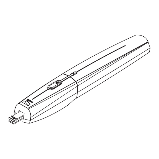
- Page 6 ⑦ Descrizione delle parti ② 1. Motoriduttore 2. Staffa cancello e vite di fissaggio 3. Staffa pilastro e vite di fissaggio ④ 4. Boccola per staffa pilastro 5. Chiave per sblocco ⑥ ① 6. Cover 1 7. Cover 2 M8 x 35 ⑤...
- Page 7 Attrezzi e materiali Assicurarsi di avere tutti gli strumenti e il materiale necessario per effettuare l’installazione nella massima sicurezza e secondo le normative vigenti. In figura alcuni esempi di attrezzatura per l’installatore. Tipi di cavi e spessori minimi Lunghezza cavo Lunghezza cavo Collegamento Tipo cavo...
- Page 8 Posa dei tubi corrugati Preparare le scatole di derivazione e tubi corrugati necessari per i collegamenti provenienti dal pozzetto di derivazione. Per il collegamento del motoriduttore si consiglia un tubo corrugato Ø 60 mm, per gli accessori invece, si consigliano tubi Ø 25 mm. ...
- Page 9 Fissare la staffa al pilastro ❶ con viti e tasselli adeguati. Se il pilastro è di metallo, la staffa può essere saldata. Nota: i fori sulla staffa permettono una ulteriore variazione dell'angolo di apertura dell'anta. Fissare oppure saldare la staffa al cancello ❷ . ❷...
- Page 10 Aprire l'anta (i grani dei fermi meccanici sono allentati) e infi lare il perno nel foro della staff a cancello. Fissare con la rondella UNI 6593 Ø 10 e la vite UNI 5739 M10 X 10 fornite Determinazione dei punti di finecorsa Prima di procedere con la determinazione dei punti di fi...
- Page 11 ⚠ NON RIMUOVERE la cover 2 senza averla fatta scorrere. ❹ ❻ ⚠ ❺ In apertura In chiusura Raggiungere il punto di apertura anta desiderato e Chiudere completamente l'anta e portare il fermo portare il fermo meccanico in battuta con la slitta di meccanico in battuta con la slitta di azionamento.
- Page 12 Collegamento di due motoriduttori M1 N1 ENC1 M2 N2 ENC2 Motoriduttore con encoder (M2) 24 V DC, ritardato in chiusura. Motoriduttore con encoder (M1) 24 V DC, ritardato in apertura. Collegamento di un motoriduttore M2 N2 ENC2 Motoriduttore con encoder (M2) 24 V DC Collegamento per apertura verso l'esterno ⚠...
- Page 13 Procedere ai collegamenti elettrici come indicato in figura. M1 N1 ENC1 M2 N2 ENC2 Motoriduttore con encoder (M1) 24 V DC, ritardato in chiusura. Motoriduttore con encoder (M2) 24 V DC, ritardato in apertura. OPERAZIONI FINALI Fissaggio delle cover Terminati i collegamenti elettrici e la messa in funzione, inserire le cover come di seguito indicato ⚠...
- Page 14 SBLOCCO DEL MOTORIDUTTORE ⚠ L’operazione deve essere effettuata in assenza di tensione. Lo sblocco manuale del motoriduttore può causare un movimento incontrollato del cancello, se questo presenta problemi meccanici o se non è bilanciato. SBLOCCO ❶ ❸ ❷ BLOCCO ❶ ❸...
- Page 15 MANUTENZIONE Manutenzione periodica ☞ Prima di qualsiasi operazione di manutenzione, togliere la tensione, per evitare possibili situazioni di pericolo causate da accidentali movimentazioni del dispositivo. Registro manutenzione periodica a cura dell’utente (semestrale) Data Annotazioni Firma Manutenzione straordinaria ⚠ La seguente tabella serve per registrare gli interventi di manutenzione straordinaria, di riparazione e di miglioramento eseguiti da ditte esterne specializzate.
- Page 16 __________________________ DISMISSIONE E SMALTIMENTO ☞ CAME S.p.A. implementa all’interno dei propri stabilimenti un Sistema di Gestione Ambientale certificato e conforme alla norma UNI EN ISO 14001 a garanzia del rispetto e della tutela dell’ambiente. Vi chiediamo di continuare l’opera di tutela dell’ambiente, che CAME considera uno dei fondamenti di sviluppo delle proprie strategie operative e di mercato, semplicemente osservando brevi indicazioni in materia di smaltimento: SMALTIMENTO DELL’IMBALLO...
- Page 17 GEARMOTOR FOR SWING GATES FA00021-E N Installation manual SWN20 - SWN25 English...
- Page 18 WARNING! Important safety instructions for people: READ CAREFULLY! OREWORD BUTTONS KEY SWITCHES MAGNETIC READERS • T 1.85 M HIS PRODUCT MUST ONLY BE USED FOR ITS INTENDED SO ON MUST BE INSTALLED AT LEAST FROM PURPOSE NY OTHER USE IS DANGEROUS AME S THE PERIMETER OF THE GATE S WORKING AREA...
- Page 19 • JOINTS AND SLIDE RAILS PROPERLY LUBRICATED PERFORM FUNCTIONAL CHECKS ON THE PHOTOCELLS AND SENSITIVE SAFETY EDGES EVERY SIX MONTHS O CHECK WHETHER THE PHOTOCELLS ARE WORKING WAVE AN OBJECT IN FRONT OF THEM WHILE THE GATE IS CLOSING IF THE GEARMOTOR INVERTS ITS DIRECTION OF TRAVEL OR SUDDENLY STOPS PHOTOCELLS ARE WORKING PROPERLY HIS IS THE ONLY...
- Page 20 Aluminium and ABS cover, worm screw based reduction system, crown and conical torque. Intended use This gearmotor is designed to power and operate swing gates in private homes and apartment blocks. Any installation other than what is detailed in this manual is prohibited. Limits to use SWN20 SWN25 1,25 1,75 2,25...
- Page 21 Technical data Type SWN20 SWN25 Protection rating (IP) Control panel power supply (V - 50/60 Hz) 230 AC Power supply motor (V) 24 DC Max draw (A) Maximum power (W) Duty cycle (%) Opening time at 90° (s) Operating temperature (°C) -20 ÷...
- Page 22 ⑦ Description of parts ② 1. Gearmotor 2. Gate bracket and fastening screw 3. Post bracket and fastening screw ④ 4. Bushing for post bracket 5. Release key ⑥ ① 6. Cover 1 7. Cover 2 M8 x 35 ⑤ ③...
- Page 23 Tools and materials Make sure you have all the tools and materials you will need for installing in total safety and in compliance with applicable regulations. The figure shows some of the equipment installers will need. Cable types and minimum thicknesses Cable length Cable length Connection...
- Page 24 Laying the corrugated tubes Set up the junction boxes and corrugated tubes you will need to make connections coming from the junction pit. To connect the gearmotor we suggest a Ø 60 mm corrugated tube. Whereas for the accessories we suggest Ø...
- Page 25 Fasten the bracket to the post ❶using suitable anchors and screws. If the post is made of metal, the bracket can be welded to it. Note: the holes on the bracket are for further opening angle variations of the gate leaf. Fasten or weld the bracket to the gate ❷...
- Page 26 Open the gate leaf (the grub screws on the mechanical stops are loose) and fi t the pin into the gate bracket. Fasten using the UNI6593 washer Ø 10 and the supplied UNI 5739 M10 X 10 bolt b Establishing the limit-switch points Before establishing the endstop points, you need to: release the gearmotor (see paragraph on manually releasing it) and remove covers 1 and 2 while carefully following the illustrations.
- Page 27 ⚠ DO NOT REMOVE cover 2 without fi rst sliding it. ❹ ❻ ⚠ ❺ For opening For closing Reach the gate leaf opening point you want and take Close the gate leaf completely and rest it against the mechanical stop to rest using the slide guide. the mechanical stop using the slide guide.
- Page 28 Connecting two gearmotors M1 N1 ENC1 M2 N2 ENC2 Gearmotor with encoder (M2) 24 V DC, delayed when closing. Gearmotor with encoder (M1) 24 V DC, delayed when opening. Connecting one gearmotor M2 N2 ENC2 Gearmotor with encoder (M2) 24 V DC Connection for opening outwards ⚠...
- Page 29 Make the necessary electrical connections as shown in the figure. M1 N1 ENC1 M2 N2 ENC2 Gearmotor with encoder (M1) 24 V DC, delayed when closing. Gearmotor with encoder (M2) 24 V DC, delayed when opening. FINAL OPERATIONS Fastening the covers Once you have completed all electrical connections and commissioning, fit the covers as shown here ⚠...
- Page 30 RELEASING THE GEARMOTOR ⚠ This procedure must be done with the main power cut off. The gearmotor's manual release may cause unwanted movement of the gate, if the latter has any mechanical issues or if it is not balanced. RELEASING ❶...
- Page 31 MAINTENANCE Periodic maintenance ☞ Before doing any maintenance, cut off the power supply, to prevent any hazardous situations caused by accidentally activating the gearmotor. Periodic maintenance log kept by users (every six months) Date Notes Signature Extraordinary maintenance ⚠ The following table is for logging any extraordinary maintenance jobs, repairs and improvements performed by specialized contractors.
- Page 32 ☞ CAME S.p.A. applies a certified Environmental Management System at its premises, which is compliant with the UNI EN ISO 14001 standard to ensure the environment is safeguarded.Please continue safeguarding the environment. At CAME we consider it one of the fundamentals of our operating and market strategies. Simply follow these brief disposal guidelines:...
- Page 33 MOTORÉDUCTEUR POUR PORTAILS BATTANTS FA00021-F R Manuel d’installation SWN20 - SWN25 Français...
- Page 34 ÉVITER TOUT ACCÈS IMPRUDENT À LA ZONE DE AUTRE UTILISATION EST À CONSIDÉRER COMME DANGEREUSE TRAVAIL DE LA PART DE PERSONNES NON AUTORISÉES • A SOCIÉTÉ CAME S ÉCLINE TOUTE RESPONSABILITÉ NOTAMMENT DES MINEURS ET DES ENFANTS MANIPULER EN CAS D ÉVENTUELS DOMMAGES PROVOQUÉS PAR DES...
- Page 35 COMMANDE AFIN D ÉVITER L ACTIONNEMENT INVOLONTAIRE NE LUI AURAIENT PAS ÉTÉ EXPRESSÉMENT DEMANDÉES ET QUI . • L’ DE L AUTOMATISME APPAREIL PEUT ÊTRE UTILISÉ NE SERAIENT PAS INDIQUÉES DANS LES MANUELS OUR LES PAR DES ENFANTS ÂGÉS D AU MOINS ANS ET PAR DES RÉPARATIONS...
- Page 36 Couvercle en aluminium et ABS, système de réduction avec vis sans fin, couronne et couple conique. Utilisation prévue Le motoréducteur a été conçu pour motoriser des portails battants à usage résidentiel ou collectif. Toute installation et toute utilisation autres que celles qui sont indiquées dans ce manuel sont interdites. SWN20 Limites d’utilisation SWN25 1,25...
- Page 37 Données techniques Type SWN20 SWN25 Degré de protection (IP) Alimentation armoire (V - 50/60 Hz) 230 AC Alimentation moteur (V) 24 DC Absorption max. (A) Puissance max. (W) Intermittence/Fonctionnement (%) Temps d'ouverture à 90° (s) Température de fonctionnement (°C) -20 à +55 Classe de l’appareil...
- Page 38 ⑦ Description des parties ② 1. Motoréducteur 2. Étrier portail et vis de fixation 3. Étrier pilier et vis de fixation ④ 4. Douille pour étrier pilier 5. Clé de déblocage ⑥ ① 6. Couvercle 1 7. Couvercle 2 M8 x 35 ⑤...
- Page 39 Outils et matériel S'assurer de disposer de tous les instruments et de tout le matériel nécessaire pour effectuer l'installation en toute sécurité et conformément aux normes en vigueur. La figure illustre quelques exemples d'outils utiles à l'installateur. Types de câbles et épaisseurs minimum Longueur câble Longueur câble Connexion...
- Page 40 Pose des gaines annelées Prévoir les boîtes de jonction et les tuyaux annelés nécessaires pour les raccordements issus du boîtier de dérivation. Il est conseillé de prévoir un tuyau annelé Ø 60 mm pour la connexion du motoréducteur et des tuyaux Ø...
- Page 41 Fixer l'étrier au pilier ❶ à l'aide des vis et des chevilles spécifiques. En cas de pilier en métal, il est possible de souder l'étrier. Remarque : les trous prévus sur l'étrier permettent de varier l'angle d'ouverture du vantail. Fixer ou souder l'étrier sur le portail ❷. ❷...
- Page 42 Ouvrir le vantail (les goujons des butées mécaniques sont desserrés) et introduire le goujon dans le trou de l'étrier portail. Fixer à l'aide de la rondelle UNI 6593 Ø 10 et de la vis UNI 5739 M10 X 10 fournies Détermination des points de fin de course Avant l'identifi...
- Page 43 ⚠ N'ENLEVER le couvercle 2 qu'après l'avoir fait glisser. ❹ ❻ ⚠ ❺ En phase d'ouverture En phase de fermeture Atteindre le point d'ouverture du vantail souhaité Fermer complètement le vantail et amener la butée et amener la butée mécanique contre le rail mécanique contre le rail d'actionnement.
- Page 44 Connexion de deux motoréducteurs M1 N1 ENC1 M2 N2 ENC2 Motoréducteur avec encodeur (M2) 24 VDC, retardé à la fermeture. Motoréducteur avec encodeur (M1) 24 VDC, retardé à l'ouverture. Connexion d'un motoréducteur M2 N2 ENC2 Motoréducteur avec encodeur (M2) 24 VDC Connexion pour l'ouverture vers l'extérieur ⚠...
- Page 45 Effectuer les branchements électriques comme indiqué sur la figure. M1 N1 ENC1 M2 N2 ENC2 Motoréducteur avec encodeur (M1) 24 VDC, retardé à la fermeture. Motoréducteur avec encodeur (M2) 24 VDC, retardé à l'ouverture. OPÉRATIONS FINALES Fixation des couvercles Au terme des branchements électriques et de la mise en fonction, mettre les couvercles comme indiqué ci-dessous. ⚠...
- Page 46 DÉBLOCAGE DU MOTORÉDUCTEUR ⚠ Mettre hors tension avant d'effectuer cette opération. Le déblocage manuel du motoréducteur peut provoquer un mouvement incontrôlé du portail si ce dernier présente des problèmes mécaniques ou s'il n'est pas équilibré. DÉBLOCAGE ❶ ❸ ❷ BLOCAGE ❶...
- Page 47 ENTRETIEN Entretien périodique ☞ Avant toute autre opération d'entretien, il est conseillé de mettre hors tension pour éviter toute situation de danger provoquée par des déplacements accidentels du dispositif. Registre d'entretien périodique tenu par l'utilisateur (semestriel) Date Remarques Signature Entretien curatif ⚠...
- Page 48 __________________________ MISE AU REBUT ET ÉLIMINATION ☞ CAME S.p.A. adopte dans ses établissements un Système de Gestion Environnementale certifié et conforme à la norme UNI EN ISO 14001 qui garantit le respect et la sauvegarde de l'environnement. Nous vous demandons de poursuivre ces efforts de sauvegarde de l'environnement, que CAME considère comme l'un des fondements du...
- Page 49 ПРИВОД ДЛЯ РАСПАШНЫХ ВОРОТ FA00021-RU Инструкция по монтажу SWN20 - SWN25 Русский...
- Page 50 ПО НАЗНАЧЕНИЮ ЛЮБОЕ ДРУГОЕ ДАННЫМ ИНСТРУКЦИЯМ ПО БЕЗОПАСНОСТИ ХРАНИТЕ ИХ В ПРИМЕНЕНИЕ РАССМАТРИВАЕТСЯ КАК ОПАСНОЕ CAME S НАДЕЖНОМ И БЕЗОПАСНОМ МЕСТЕ СНИМАЕТ С СЕБЯ ВСЯКУЮ ОТВЕТСТВЕННОСТЬ ЗА ВОЗМОЖНЫЙ МОНТАЖ • УЩЕРБ НАНЕСЕННЫЙ В РЕЗУЛЬТАТЕ НЕПРАВИЛЬНОГО ОБОЗНАЧЬТЕ И ОТДЕЛИТЕ УЧАСТОК ПРОВЕДЕНИЯ...
- Page 51 УПРАВЛЕНИЯ ИЛИ НАХОДИТЬСЯ В ЗОНЕ ДВИЖЕНИЯ ВОРОТ КАТЕГОРИЧЕСКИ ЗАПРЕЩАЕТСЯ ВЫПОЛНЯТЬ ДЕЙСТВИЯ НЕ • НЕОБХОДИМО ДЕРЖАТЬ БРЕЛОКИ ПЕРЕДАТЧИКИ И ДРУГИЕ УКАЗАННЫЕ И НЕ ПРЕДУСМОТРЕННЫЕ В ИНСТРУКЦИЯХ ДЛЯ УСТРОЙСТВА УПРАВЛЕНИЯ В НЕДОСТУПНОМ ДЛЯ ДЕТЕЙ РЕМОНТА ВНЕПЛАНОВОГО ТЕХНИЧЕСКОГО ОБСЛУЖИВАНИЯ МЕСТЕ ВО ИЗБЕЖАНИЕ СЛУЧАЙНОГО ЗАПУСКА СИСТЕМЫ И...
- Page 52 ходовой винт зубчатой передачей. Назначение Привод разработан для автоматизации распашных ворот в частном жилом секторе и кондоминиумах. Запрещается использовать устройство не по назначению и устанавливать его методами, отличными от описанных в настоящей инструкции. Ограничения в использовании SWN20 SWN25 1,25 1,75 2,25 2,75 Ширина...
- Page 53 Технические характеристики Модель SWN20 SWN25 Класс защиты (IP) Напряжение электропитания (В, 50/60 Гц) ~230 Электропитание двигателя (В) Макс. потребляемый ток (А) Макс. мощность (Вт) Интенсивность использования (%) Время открывания на 90° (с) Диапазон рабочих температур (°C) -20 – +55 Класс устройства Передаточное отношение (i) 1/36 Толкающее...
- Page 54 Основные компоненты ⑦ ② 1. Привод 2. Передний кронштейн с креплением привода 3. Задний кронштейн с креплением ④ привода ⑥ ① 4. Втулка 5. Ключ для разблокировки 6. Крышка привода 7. Крышка винта M8 x 35 ⑤ UNI 7474 M8 ③...
- Page 55 Инструменты и материалы Перед началом монтажных работ убедитесь в наличии всех необходимых инструментов и материалов, которые позволят произвести установку системы в полном соответствии с действующими нормами безопасности. На рисунке представлен минимальный набор инструментов, необходимых для проведения монтажных работ. Тип и сечение кабелей Длина...
- Page 56 Прокладка гофрированных труб Подготовьте разветвительные коробки и гофрированные трубы, необходимые для электрических соединений, исходящих из разветвительного колодца. Для подключения привода рекомендуется использовать гофрированную трубу Ø 60 мм, а для аксессуаров — трубы Ø 25 мм. Количество гофрированных труб зависит от варианта системы и предусмотренных...
- Page 57 Прикрепите кронштейн к столбу ❶ с помощью надлежащих саморезов и дюбелей. Если столб ворот металлический, приварите к нему кронштейн. Примечание: отверстия в заднем кронштейне позволяют дополнительно изменять угол открывания створки. Прикрепите или приварите передний кронштейн к створке ❷. ❷ ❶ Крепление...
- Page 58 Откройте створку (отвернув предварительно регулировочные винты механических упоров привода) и установите крепление втулки ходового винта в отверстие переднего кронштейна. Зафиксируйте его с помощью прилагаемых шайбы UNI 6593 Ø 10 и винта UNI 5739 M10 X 10 Регулировка крайних положений Прежде чем приступить к регулировке конечных положений, необходимо: разблокировать привода (см. пункт...
- Page 59 ⚠ НЕ СНИМАЙТЕ крышку винта, не сдвинув ее вперед. ❹ ❻ ⚠ ❺ При открывании При закрывании Отведя створку в желаемое положение при Плотно закрыв створку, установите открывании, установите механический упор механический упор вплотную к втулке и вплотную к втулке и закрутите фиксирующие закрутите...
- Page 60 Подключение двух приводов M1 N1 ENC1 M2 N2 ENC2 Привод с энкодером (M2) =24 В, с задержкой при закрывании. Привод с энкодером (M1) =24 В, с задержкой при открывании. Подключение одного привода M2 N2 ENC2 Привод с энкодером (M2) =24 В Подключение...
- Page 61 Выполните электрические подключения, как показано на рисунке. M1 N1 ENC1 M2 N2 ENC2 Привод с энкодером (M1) =24 В, с задержкой при закрывании Привод с энкодером (M2) =24 В, с задержкой при открывании ЗАКЛЮЧИТЕЛЬНЫЕ РАБОТЫ Крепление крышки После выполнения всех электрических подключений и подготовки системы к работе установите крышки, как показано...
- Page 62 РАЗБЛОКИРОВКА ПРИВОДА ⚠ Перед выполнением операции обесточьте систему. Ручная разблокировка привода может привести к неожиданному движению ворот, если они повреждены или надлежащим образом несбалансированы. РАЗБЛОКИРОВКА ❶ ❸ ❷ БЛОКИРОВКА ❶ ❸ ❷ УСТРАНЕНИЕ НЕИСПРАВНОСТЕЙ НЕИСПРАВНОСТЬ ВОЗМОЖНАЯ ПРИЧИНА СПОСОБ УСТРАНЕНИЯ Ворота не •...
- Page 63 ТЕХНИЧЕСКОЕ ОБСЛУЖИВАНИЕ Периодическое техническое обслуживание ☞ Перед выполнением работ по техническому обслуживанию отключите питание во избежание возникновения опасных ситуаций, вызванных непроизвольным движением устройства. Журнал периодического технического обслуживания, заполняемый пользователем (каждые 6 месяцев) Дата Выполненные работы Подпись Внеплановое техническое обслуживание и ремонт ⚠...
- Page 64 ________________________________________________________________________________ ____________________________ УТИЛИЗАЦИЯ ☞ CAME S.p.A. имеет сертификат системы защиты окружающей среды UNI EN ISO 14001, гарантирующий экологическую безопасность на ее заводах. Мы просим, чтобы вы продолжали защищать окружающую среду. САМЕ считает одним из фундаментальных пунктов стратегии рыночных отношений выполнение...