steute ES 95 Instructions De Montage Et De Câblage
Masquer les pouces
Voir aussi pour ES 95:
- Instructions de montage (10 pages) ,
- Instructions de montage (12 pages)
Publicité
Liens rapides
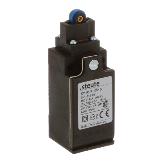
ES/EM 95
//
Montage- und Anschlussanleitung / Positionsschalter
Mounting and wiring instructions / Position switch
Instructions de montage et de câblage / Interrupteur de position
Istruzioni di montaggio e collegamento / Interruttori di posizione
Instruções de montagem e instalação / Chaves fim de curso
Инструкции Монтаж и Коммутация / Переключатели положения
Deutsch (Originalsprache)
Bestimmung und Gebrauch
Die Positionsschalter mit Sicherheitsfunktion ES/EM 95 dienen dem
Einsatz in Sicherheitsstromkreisen zur Stellungsüberwachung beweg-
licher Schutzeinrichtungen nach EN ISO 14119 (EN 1088) Bauart 1 und
EN 60947-5-1.
Befestigung / Anschluss
Den Positionsschalter auf einer ebene Fläche befestigen. Bei der Mon-
tage ist darauf zu achten, dass ein Verschieben des Positionsschalters
mit Sicherheitsfunktion auch im Fehlerfall verhindert wird. Den Schal-
ter gegen unbefugtes Lösen sichern, z. B. mit Einweg-Sicherheits-
schrauben. Bei der Montage des Schalters sind die Anforderungen
nach EN ISO 14119, insbesondere die Punkte 5.2 und 5.3, zu berück-
sichtigen! Bitte beachten Sie auch die Hinweise der Normen EN ISO
12100 und EN ISO 14120.
Hinweise
Der elektrische Anschluss darf nur von autorisiertem Fachperso-
nal durchgeführt werden. Der Schalter darf nicht als mechanischer
Anschlag verwendet werden. Die Gebrauchslage ist beliebig. Um-
bauten und Veränderungen am Schalter sind nicht gestattet. Die
hier beschriebenen Produkte wurden entwickelt, um als Teil einer
Gesamtanlage oder Maschine sicherheitsgerichtete Funktionen zu
übernehmen. Ein komplettes sicherheitsgerichtetes System enthält in
der Regel Sensoren, Auswerteeinheiten, Meldegeräte und Konzepte
für sichere Abschaltungen. Hierzu ist auch eine Validierung nach EN
ISO 13849-2 bzw. nach DIN EN 62061 erforderlich. Desweiteren kann
der Performance-Level bzw. SIL-CL-Level durch Verkettung von
mehreren Sicherheitsbauteilen und anderen sicherheitsgerichteten
Geräten, z. B. Reihenschaltung von Sensoren, niedriger ausfallen als
die Einzellevel. Es liegt im Verantwortungsbereich des Herstellers
einer Anlage oder Maschine, die korrekte Gesamtfunktion sicherzu-
stellen. steute übernimmt keine Haftung für Empfehlungen, die durch
diese Beschreibung gegeben oder impliziert werden. Änderungen,
die dem technischen Fortschritt dienen, vorbehalten. Aufgrund dieser
Beschreibung können keine neuen, über die allgemeinen steute-
Lieferbedingungen hinausgehenden Garantie-, Gewährleistungs- oder
Haftungsansprüche abgeleitet werden.
Wartung
Bei rauen Betriebsbedingungen empfehlen wir eine regelmäßige
Wartung mit folgenden Schritten:
1. Prüfen des Betätigers auf Leichtgängigkeit.
2. Entfernen von Schmutzresten.
3. Nachschmieren der Wellen oder Bolzen.
4. Prüfen der Leitungseinführung und -anschlüsse.
English
Destination and use
The position switch ES/EM 95 for safety circuits is used in safety cir-
cuits to monitor the position of mobile safety guards to EN ISO 14119
(EN 1088) type 1 and EN 60947-5-1.
Mounting / Wiring
The position switch should be mounted on an even surface. Please en-
sure that, even in case of failure, the poasition switch cannot be moved
from its position. For protection against manipulation use oneway
safety screws which are optional available. Please adjust screws at
both sides with the same number of turns with a screwdriver. When
mounting the switch please observe the requirements of EN ISO
14119, especially paragraph 5.2 and 5.3! Please observe the instruc-
tions in the standards EN ISO 12100 and EN ISO 14120.
Notices
The electrical connection may only be carried out by authorised per-
sonnel. Do not use the sensor as mechanical endstop. Any mounting
position is possible. Reconstruction and alterations at the switch are
not allowed. The described products have been developed in order
to assume safety functions as a part of an entire plant or machine. A
complete safety system normally covers sensors, monitoring modules,
indicator switches and concepts for safe disconnection. Therefore a
validation according to EN ISO 13849-2 or DIN EN 62061 is required.
Furthermore the Performance Level and SIL CL Level can be lower
than the single level because of the combination of several safety
components and other safety-related devices, e.g. by serial connec-
tion of sensors. The responsibility taken by the manufacturer of a plant
or machine implies to secure the correct general function. Subject to
technical modifications. Moreover steute does not assume any liability
for recommendations made or implied by this description. Subject to
technical modifications. From this description new claims for guaran-
tee, warranty or liability cannot be derived beyond the general terms
and conditions of delivery.
Maintenance
With rough conditions, we recommend routine maintenance
as follows:
1. Check actuator for easy operation.
2. Remove all dirt or particles.
3. Lubricate cam and roller shafts.
4. Check sealing of the cable or conduit connections.
Publicité

Manuels Connexes pour steute ES 95


Sommaire des Matières pour steute ES 95
- Page 1 Subject to Geräten, z. B. Reihenschaltung von Sensoren, niedriger ausfallen als technical modifications. Moreover steute does not assume any liability die Einzellevel. Es liegt im Verantwortungsbereich des Herstellers for recommendations made or implied by this description. Subject to einer Anlage oder Maschine, die korrekte Gesamtfunktion sicherzu- technical modifications.
- Page 2 à titre d’information et sans engagement di un impianto o macchinario implica di garantire il corretto funziona- contractuel de la part de steute. mento generale. Steute non si assume alcuna responsabilità per sug- gerimenti impliciti od espliciti forniti da questa descrizione. Soggetta Entretien a modifiche tecniche.
- Page 3 необходима проверка на соответствие нормам DIN EN ISO 13849-2 individual. A steute não assume qualquer responsabilidade por reco- либо DIN EN 62061. Кроме того в результате последовательного mendações deduzidas ou implícitas a esta descrição. Estão reservados включения...
- Page 4 Инструкции по монтажу Kontakte Contacts Contacts Contatti Contatos Контакты ES 95 1Ö/1S EM 95 1Ö/1S ES 95 UE ES 95 2Ö ES 95 2S Die dargestellten Schaltsymbole beziehen sich auf den unbetätigten Zustand. Contact symbols are shown for the not actuated switch.
- Page 5 ES/EM 95 Montage- und Anschlussanleitung / Positionsschalter Mounting and wiring instructions / Position switch Instructions de montage et de câblage / Interrupteur de position Istruzioni di montaggio e collegamento / Interruttori di posizione Instruções de montagem e instalação / Chaves fim de curso Инструкции...
- Page 6 ES/EM 95 Montage- und Anschlussanleitung / Positionsschalter Mounting and wiring instructions / Position switch Instructions de montage et de câblage / Interrupteur de position Istruzioni di montaggio e collegamento / Interruttori di posizione Instruções de montagem e instalação / Chaves fim de curso Инструкции...
- Page 7 We hereby declare that the above mentioned electrical equipment conforms to the named directive. Löhne, 25. November 2016/November 25th, 2016 Ort und Datum der Ausstellung Rechtsverbindliche Unterschrift, Marc Stanesby (Geschäftsführer) Place and date of issue Legally binding signature, Marc Stanesby (Managing Director) steute Schaltgeräte GmbH & Co KG, Brückenstr. 91, 32584 Löhne, Germany...
- Page 8 Zusatzinformation zu Montage- und Anschlussanleitungen Additional information on mounting and wiring instructions Information complémentaire aux instructions de montage et de câblage Ulteriori informazioni sulle istruzioni di collegamento e montaggio Informação adicional para as instruções de montagem Дополнительная информация по монтажу и инструкциям по подключению Auf Anfrage erhalten Sie diese Montage- und Anschlussanleitung auch При...