Publicité
Les langues disponibles
Les langues disponibles
Liens rapides
Bedienungsanleitung / Operation Instructions / Manuel d'utilisation
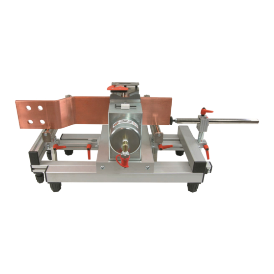
ALFRA Stromschienen Biege- und Lochstanzgerät – LPV
für Stromschienen 120 x 12 mm mit Biegematrize und Winkelanzeiger
ALFRA Busbar Bending and Hole Punching Unit – LPV
for busbars 120 x 12 mm with angle die and angle indicator
ALFRA appareil de pliage et de percage – LPV
pour barres conductrices 120 x 12 mm avec matrice de pliage et indicateur d'angle
Artikel Nr. 03256 / Prod.-No. 03256 / N° de produit 03256
Publicité

Manuels Connexes pour ALFRA LPV


Sommaire des Matières pour ALFRA LPV
- Page 1 ALFRA Stromschienen Biege- und Lochstanzgerät – LPV für Stromschienen 120 x 12 mm mit Biegematrize und Winkelanzeiger ALFRA Busbar Bending and Hole Punching Unit – LPV for busbars 120 x 12 mm with angle die and angle indicator ALFRA appareil de pliage et de percage – LPV pour barres conductrices 120 x 12 mm avec matrice de pliage et indicateur d’angle...
- Page 2 Inhaltsverzeichnis / Contents / Table des matières Bestimmungsgemäße Verwendung, Beschreibung, Vor Inbetriebnahme Technische Daten, Lieferumfang, Inbetriebnahme, Einstellen lesen und Seite 3 des Längenanschlags, Biegen, Lochstanzen, Biegemaße, aufbewahren! Höhenverstellung, Explosionszeichnung, Teileliste. Specified conditions of use, Description, Technical data, Please read and save Scope of supply, Commissioning, Adjusting the longitudinal Page 11 these instructions!
- Page 3 Das Gerät besteht aus einem Grundgestell aus Aluminiumprofil, in dem der Grundkörper eingesetzt ist. Der Grundkörper entspricht dem unseres Standardgerätes. Da der Grundkörper bei der LPV-Version fest in den Rahmen eingebaut ist, ist das Gerät zum Einstellen der Arbeitshöhe mit zwei höhenverstellbaren Rollenauflagen ausgestattet, die leicht ausgewechselt werden können.
- Page 4 Lieferumfang • Aluminiumrahmen mit Auszug um ca. 380 mm • Grundkörper • mechanischer Winkelableser (kompl.) • Biegematrize (H=120 mm) • Rollenauflagen • Längenanschlag Inbetriebnahme Um die Einheit Stromschienen Biege- Lochstanzgerät und Hydraulikpumpe in Betrieb zu nehmen, muß das Gerät ausgerichtet und mittels Schnellkupplungen mit der Hydraulikeinheit verbunden werden. Das Grundgestell kann durch Verdrehen der Füße (6) so ausgerichtet werden, daß...
- Page 5 Der Schleppzeiger des Winkelablesers ist nach dem Einlegen der Stromschiene in die Ausgangsposition zu bringen (Ablesenadel befindet sich bei 0° ). Auf dem Kolben sind drei Warnringe eingraviert. Fahren Sie den Stempel nie über den dritten Ring hinaus! Lochstanzen • Entfernen Sie die Biegematrize (66) und den Winkelableser (69) aus dem Grundkörper. •...
- Page 6 Biegemaße...
- Page 7 Höhenverstellung...
- Page 8 Explosionszeichnung...
- Page 9 Teileliste Pos. Menge Benennung Art.Nr. Profil 40x40x491 links 03256001 Profil 40x40x491 rechts 03256002 Profil 40x40x250 03256003 Profil 40x40x258 03256004 Abdeckkappe 40x40 03256005 Handstellfuß 40 03256006 Gewindeplatte E M8 03256007 Zylinderschraube ISO 4762 DIN 912 – M6 x 25 – 8.8 Gewindeplatte E M6 03256009 Aluplatte 40x10x180...
- Page 10 Grundkörper 03200-082 Stützbuchse (gehärtet) 03200-082A Gewindestift DIN 916 – M10 x 20 – 45H Zylinderschraube ISO 4762 03200-083 Kolben (gehärtet) 03200-081 Gewindestift DIN 915 – M6 x 8 – 45H Zylinderdichtung 45x65x10 03200-079 Druckfeder 03200-076 Anschlagring 03200-107 Zylinder 03200-078 Winkeleinschraubadapter 03200-077A Nippel 03200-077...
- Page 11 Because with the LPV version the base body is fixed onto the frame, the unit is equipped with two roller supports which are adjustable for height and are used for setting the working height of the conductor rail when carrying out bending and punching.
- Page 12 Scope of supply • aluminium frame with 380 mm extension • one base body • mechanical angle reading device (complete) • bending die (H = 120 mm) • roller supports • lenght stop Commissioning In order to start the conductor rail bending and punching unit and the hydraulic pump, the unit has to be first aligned and then connected to the hydraulic unit with the quick-couplings.
- Page 13 Punching holes • Remove the bending die plate (66) and the angle reading device (69) from the base body. • Firstly set the die in the receiving holes in the base body. Then set the punch with the neoprene stripper and with the pressure piece, if necessary, in the hydraulic piston.
- Page 14 Bending dimensions...
- Page 15 Hight adjustment...
- Page 16 Exploded drawing...
- Page 17 Part list Pos. Qty. Description Prod. no. Profile 40x40x491 left 03256001 Profile 40x40x491 right 03256002 Profile 40x40x250 03256003 Profile 40x40x258 03256004 Cover cap 40x40 03256005 Adjustable foot 40 03256006 Threaded plate E M8 03256007 Cylinder head screw ISO 4762 DIN 912 – M6 x 25 – 8.8 Threaded plate E M6 03256009 Aluminum plate 40x10x180...
- Page 18 Roll Ø12x400 03256044 Ruler 0 - 55mm 03256045 Ring 20mm Ø30/Ø20,2 03256046 Ring 10mm Ø30/Ø20,2 03256047 Ring 5mm Ø30/Ø 20,2 03256048 Set screw DIN 913 – M6 x 5 – 45H Base body 03200-082 Bracket socket (hardened) 03200-082A Set screw DIN 916 –...
- Page 19 Utilisation conforme L’appareil de pliage et de perçage des barres conductrices – LPV permet de plier grâce à son cylindre universel les barres de cuivre et d’aluminium jusqu’à 120 mm de large et jusqu’à 12 mm d’épaisseur. Il est possible d’effectuer des trous ronds ainsi que des trous oblongs du diamètre 6,6 mm jusqu’au diamètre 21,0 mm et une longueur jusqu’à...
- Page 20 Compris dans la livraison standard • un cadre tubulaire avec dispositif de rallonge de 700 mm • un appareil de base • un indicateur d’angle mécanique (complet) • une matrice de pliage (hauteur: 120 mm) • deux supports de rouleaux •...
- Page 21 Sur le piston sont gravés 3 anneaux d’avertissement de couleur rouge. Ne jamais aller plus loin que le troisième anneau avec le piston. Perçage • Veuillez enlever la matrice de pliage et l’indicateur d’angle de l’appareil de base. • La matrice devra trouver son logement dans la perforation de l’appareil de base. Quant au poinçon avec le dévetisseur néoprène et éventuellement des pièces de pression, il prendra place dans le piston hydraulique.
- Page 22 Dimensions de pliage...
- Page 23 Proposition réglage en hauteur...
- Page 24 Vue éclatée...
- Page 25 Liste des pièces Pos. Qty. Désignation N° de produit Profil 40x40x491 à gauche 03256001 Profil 40x40x491 à droite 03256002 Profil 40x40x250 03256003 Profil 40x40x258 03256004 Capuchon 40x40 03256005 Pied à réglage manuel 40 03256006 Plaque filetée E M8 03256007 Vis à tête cylindrique DIN 912 DIN 912 –...
- Page 26 Cylindre Ø12x400 03256044 Règle 0 – 55 mm 03256045 Bague 20 mm Ø30/Ø20,2 03256046 Bague 10 mm Ø30/Ø20,2 03256047 Bague 5 mm Ø30/Ø 20,2 03256048 Tige filetée DIN 913 – M6 x 5 – 45H Corps de base 03200-082 Douille de support (trempé) 03200-082A Tige filetée DIN 916 –...
- Page 28 Alfred Raith GmbH Tel. 06205-3051-0 2. Industriestr. 10 Fax 06205-3051-150 D-68766 Hockenheim Internet: www.alfra.de E-mail: info@alfra.de...