Publicité
Les langues disponibles
Les langues disponibles
Liens rapides
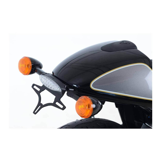
FITTING INSTRUCTIONS FOR LP0237BK LICENCE PLATE BRACKET
TRIUMPH STREET CUP 2017-
Page | 1
THIS KIT CONTAINS THE ITEMS PICTURED AND LABELLED BELOW.
DO NOT PROCEED UNTIL YOU ARE SURE ALL PARTS ARE PRESENT.
Please note that the way the kit is packed does not necessarily represent the way of mounting to the bike.
T
(
).
HE PARTS SHOWN MAY BE REPRESENTATIVE ONLY
FOR CLARITY OF INSTRUCTIONS ONLY
x2
x4
x2
x2
x2
x2
R&G
Unit 1, Shelley's Lane, East Worldham, Alton, Hampshire, GU34 3AQ
Tel: +44 (0)1420 89007 Fax: +44 (0)1420 87301
www.rg-racing.com
Email:
info@rg-racing.com
Publicité

Manuels Connexes pour R&G LP0237BK


Sommaire des Matières pour R&G LP0237BK
- Page 1 FITTING INSTRUCTIONS FOR LP0237BK LICENCE PLATE BRACKET TRIUMPH STREET CUP 2017- Page | 1 THIS KIT CONTAINS THE ITEMS PICTURED AND LABELLED BELOW. DO NOT PROCEED UNTIL YOU ARE SURE ALL PARTS ARE PRESENT. Please note that the way the kit is packed does not necessarily represent the way of mounting to the bike.
- Page 2 Page | 2 LEGEND ITEM 1 = LA0003 TAIL LIGHT (x1). ITEM 2 = LA0003 SHROUD (x1). ITEM 3 = LICENCE PLATE BRACKET (TB0237 Part 1) (x1). ITEM 4 = THREADED SPACER (S0977 – 12mm LONG) (x1). ITEM 5 = M6 WASHERS (20mm OD) (x5). ITEM 6 = M6 NYLOC NUTS (x4).
-
Page 3: Tools Required
TOOLS REQUIRED Set of metric Allen keys to include 4, 5 & 6mm A/F size. Torx sockets to include T20 & T30 sizes. 6, 8, 10 & 13mm spanners or sockets. Cable cutters. Page | 3 MAXIMUM TORQUE SETTINGS ... - Page 4 Page | 4 Picture 5 Picture 6 Picture 7 Picture 8 Picture 9 Picture 10 R&G Unit 1, Shelley’s Lane, East Worldham, Alton, Hampshire, GU34 3AQ Tel: +44 (0)1420 89007 Fax: +44 (0)1420 87301 www.rg-racing.com Email: info@rg-racing.com...
- Page 5 Page | 5 Picture 11 Picture 12 Picture 13 Picture 14 Picture 15 Picture 16 R&G Unit 1, Shelley’s Lane, East Worldham, Alton, Hampshire, GU34 3AQ Tel: +44 (0)1420 89007 Fax: +44 (0)1420 87301 www.rg-racing.com Email: info@rg-racing.com...
- Page 6 Page | 6 Picture 17 Picture 18 Picture 19 Picture 20 Picture 21 Picture 22 R&G Unit 1, Shelley’s Lane, East Worldham, Alton, Hampshire, GU34 3AQ Tel: +44 (0)1420 89007 Fax: +44 (0)1420 87301 www.rg-racing.com Email: info@rg-racing.com...
- Page 7 Page | 7 Picture 23 Picture 24 Picture 25 Picture 26 Picture 27 Picture 28 R&G Unit 1, Shelley’s Lane, East Worldham, Alton, Hampshire, GU34 3AQ Tel: +44 (0)1420 89007 Fax: +44 (0)1420 87301 www.rg-racing.com Email: info@rg-racing.com...
- Page 8 Page | 8 Picture 29 Picture 30 Picture 31 Picture 32 Picture 33 Picture 34 R&G Unit 1, Shelley’s Lane, East Worldham, Alton, Hampshire, GU34 3AQ Tel: +44 (0)1420 89007 Fax: +44 (0)1420 87301 www.rg-racing.com Email: info@rg-racing.com...
- Page 9 Page | 9 Picture 35 Picture 36 Picture 37 Picture 38 Picture 39 Picture 40 R&G Unit 1, Shelley’s Lane, East Worldham, Alton, Hampshire, GU34 3AQ Tel: +44 (0)1420 89007 Fax: +44 (0)1420 87301 www.rg-racing.com Email: info@rg-racing.com...
-
Page 10: Fitting Instructions
FITTING INSTRUCTIONS To fit the R&G tail tidy, remove the seat using the key, as shown in picture 1 and disconnect the tail light/indicator connector that is arrowed in picture 1. Remove the two Torx bolts that secure the front of the rear mudguard, as shown in picture 2. ... - Page 11 Fit the remaining two M6 x 6mm long button head bolts (item 15) with two M6 washers (item 13) through the two rear mounting holes and loosely tighten into the threaded holes of the already fitted licence plate bracket, as shown in pictures 26 &...
- Page 12 head bolts and washers through the two mounting holes on the indicator bracket from underneath, ensuring to fit the large diameter M6 washer (item 5) over the exposed thread of the right side bolt only, as shown in picture 35. ...
- Page 13 or neglect. Other than identified above and subject to R&G not limiting its liability for causing death and personal injury, it shall not be liable for indirect or consequential loss and otherwise its liability shall be limited to the amounts paid by the Buyer for the Products or the fitting or service concerned.
- Page 14 NOTICE DE MONTAGE POUR LP0237BK SUPPORT DE PLAQUE TRIUMPH STREET CUP 2017- Page | 14 Le kit contient les articles exposés ci-dessous, vérifier que toutes les pièces soient présentes avant de procéder au montage. A FAÇON DONT LE KIT EST EMBALLE NE CORRESPOND PAS FORCEMENT A LA FAÇON DE MONTER LES PIECES...
- Page 15 Page | 15 LEGENDE ARTICLE 1 = LA0003 FEU DE PLAQUE (x1). ARTICLE 2 = LA0003 LINCEUL (x1). ARTICLE 3 = SUPPORT DE PLAQUE (TB0237 Partie 1) (x1). ARTICLE 4 = ENTRETOISE FILETEE (S0977 – 12mm DE LONG) (x1). ARTICLE 5 = M6 RONDELLES (20mm OD) (x5). ARTICLE 6 = M6 ECROUS (x4).
-
Page 16: Outils Requis
OUTILS REQUIS Clés Allen 4, 5 & 6mm. Clés Torx T20 & T30. Clés à douille 6, 8, 10 & 13mm. Pince coupante. Page | 16 Couples de serrage recommandés : M4 BOULON = 8Nm M5 BOULON = 12Nm M6 BOULON = 15Nm M8 BOULON = 20Nm NOTICE DE MONTAGE :... - Page 17 Prendre le support de clignotant le plus à l’arrière (article 19 – TB0203 Partie 3) et montez les clignotants de votre choix en passant les fils dans le trou le plus large du support de clignotant et en plaçant le trou du clignotant dans le trou, voir photo 21.
- Page 18 Une fois les entretoises en place, insérer les 2 boulons M6 x 35mm (article 14) avec 2 rondelles M6 (article 13) dans le cache sous siège et sous cadre avant de réinsérer 2 rondelles larges (article 5) et 2 écrous M6 (article 6) sur les extrémités du filetage, voir photos 28 &...
- Page 19 Si vous montez les minis clignotants R&G à LED, le fil noir/blanc sur les minis clignotants se connecte avec le fil vert/rouge (clignotant gauche) ou vert/rouge (clignotant droit) sur le faisceau d’origine et le fil noir sur les mini clignotants se connecte avec le fil noir sur le linceul. 1x set de résistances RGR0001 (disponible séparément) sont requises pour obtenir le bon niveau d’éclairage.