Publicité
Les langues disponibles
Les langues disponibles
Liens rapides
FITTING INSTRUCTIONS FOR LP0203BK LICENCE PLATE BRACKET
TRIUMPH STREET TWIN '16-
Page | 1
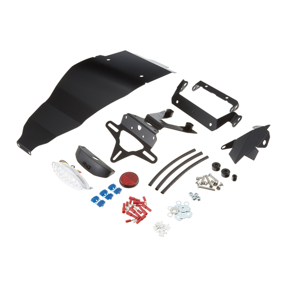
THIS KIT CONTAINS THE ITEMS PICTURED AND LABELLED BELOW.
DO NOT PROCEED UNTIL YOU ARE SURE ALL PARTS ARE PRESENT.
Please note that the way the kit is packed does not necessarily represent the way of mounting to the bike.
T
(
).
HE PARTS SHOWN MAY BE REPRESENTATIVE ONLY
FOR CLARITY OF INSTRUCTIONS ONLY
x2
x4
x2
x2
x2
x2
R&G Racing
Unit 1, Shelley's Lane, East Worldham, Alton, Hampshire, GU34 3AQ
Tel: +44 (0)1420 89007 Fax: +44 (0)1420 87301
www.rg-racing.com
Email:
info@rg-racing.com
Publicité

Manuels Connexes pour R&G LP0203BK


Sommaire des Matières pour R&G LP0203BK
- Page 1 FITTING INSTRUCTIONS FOR LP0203BK LICENCE PLATE BRACKET TRIUMPH STREET TWIN ’16- Page | 1 THIS KIT CONTAINS THE ITEMS PICTURED AND LABELLED BELOW. DO NOT PROCEED UNTIL YOU ARE SURE ALL PARTS ARE PRESENT. Please note that the way the kit is packed does not necessarily represent the way of mounting to the bike.
- Page 2 Page | 2 LEGEND ITEM 1 = LA0003 TAIL LIGHT (x1). ITEM 2 = LA0003 SHROUD (x1). ITEM 3 = LICENCE PLATE BRACKET (TB0203 Part 1) (x1). ITEM 4 = THREADED SPACER (S0977 – 12mm LONG) (x1). ITEM 5 = M6 WASHERS (20mm OD) (x5). ITEM 6 = M6 NYLOC NUTS (x4).
-
Page 3: Tools Required
TOOLS REQUIRED • Set of metric Allen keys to include 4, 5 & 6mm A/F size. • Torx sockets to include T20 & T30 sizes. • 6, 8, 10 & 13mm spanners or sockets. • Cable cutters. Page | 3 MAXIMUM TORQUE SETTINGS •... - Page 4 Page | 4 Picture 5 Picture 6 Picture 7 Picture 8 Picture 9 Picture 10 R&G Racing Unit 1, Shelley’s Lane, East Worldham, Alton, Hampshire, GU34 3AQ Tel: +44 (0)1420 89007 Fax: +44 (0)1420 87301 www.rg-racing.com Email: info@rg-racing.com...
- Page 5 Page | 5 Picture 11 Picture 12 Picture 13 Picture 14 Picture 15 Picture 16 R&G Racing Unit 1, Shelley’s Lane, East Worldham, Alton, Hampshire, GU34 3AQ Tel: +44 (0)1420 89007 Fax: +44 (0)1420 87301 www.rg-racing.com Email: info@rg-racing.com...
- Page 6 Page | 6 Picture 17 Picture 18 Picture 19 Picture 20 Picture 21 Picture 22 R&G Racing Unit 1, Shelley’s Lane, East Worldham, Alton, Hampshire, GU34 3AQ Tel: +44 (0)1420 89007 Fax: +44 (0)1420 87301 www.rg-racing.com Email: info@rg-racing.com...
- Page 7 Page | 7 Picture 23 Picture 24 Picture 25 Picture 26 Picture 27 Picture 28 R&G Racing Unit 1, Shelley’s Lane, East Worldham, Alton, Hampshire, GU34 3AQ Tel: +44 (0)1420 89007 Fax: +44 (0)1420 87301 www.rg-racing.com Email: info@rg-racing.com...
- Page 8 Page | 8 Picture 29 Picture 30 Picture 31 Picture 32 Picture 33 Picture 34 R&G Racing Unit 1, Shelley’s Lane, East Worldham, Alton, Hampshire, GU34 3AQ Tel: +44 (0)1420 89007 Fax: +44 (0)1420 87301 www.rg-racing.com Email: info@rg-racing.com...
- Page 9 Page | 9 Picture 35 Picture 36 Picture 37 Picture 38 Picture 39 Picture 40 R&G Racing Unit 1, Shelley’s Lane, East Worldham, Alton, Hampshire, GU34 3AQ Tel: +44 (0)1420 89007 Fax: +44 (0)1420 87301 www.rg-racing.com Email: info@rg-racing.com...
-
Page 10: Fitting Instructions
Page | 10 Picture 41 FITTING INSTRUCTIONS • To fit the R&G tail tidy, remove the seat using the key, as shown in picture 1 and disconnect the tail light/indicator connector that is arrowed in picture 1. • Remove the two Torx bolts that secure the front of the rear mudguard, as shown in picture 2. •... - Page 11 If fitting the rearward mounted indicator option • Take the rearward indicator bracket (item 19 – TB0203 Part 3) and fit the indicators of choice by feeding the wiring through the larger hole on the indicator bracket and locating the indicator boss within the hole, as shown in picture 21.
- Page 12 • Ensure the wiring at the rear of the bike for the indicator and tail light is neatly routed, as shown in picture 32. If fitting the forward mounted indicator option • Remove the two bolts that secure the plastic cover in place in front of the rear wheel, as shown in picture 24. •...
- Page 13 • Offer this assembly up to the underside of the underseat cover and re-fit the washers and nyloc nuts to the bolts, before re-tightening and securing in place, as shown in picture 36. • Neatly route the wiring around the side of the underseat cover (there is a small cut-out to position the wiring) and use the cable ties/cable clips supplied to neatly route the wiring if required, as shown in picture 37.
- Page 14 CONSUMER NOTICE The catalogue description and any exhibition of samples are only broad indications of the Products and R&G may make design changes which do not diminish their performance or visual appeal and supplying them in such state shall conform to the order. The Buyer acknowledges no representation or warranty (other than as to title) has been given or will apply to the Products other than those in R&G’s order or confirmatio n and the Buyer confirms it has chosen the Products as being of merchantable quality and suitable for its particular purposes.
- Page 15 NOTICE DE MONTAGE POUR LP0203BK SUPPORT DE PLAQUE TRIUMPH STREET TWIN ’16- Page | 15 Le kit contient les articles exposés ci-dessous, vérifier que toutes les pièces soient présentes avant de procéder au montage. A FAÇON DONT LE KIT EST EMBALLE NE CORRESPOND PAS FORCEMENT A LA FAÇON DE MONTER LES PIECES...
- Page 16 Page | 16 LEGENDE ARTICLE 1 = LA0003 FEU DE PLAQUE (x1). ARTICLE 2 = LA0003 LINCEUL (x1). ARTICLE 3 = SUPPORT DE PLAQUE (TB0203 Partie 1) (x1). ARTICLE 4 = ENTRETOISE FILETEE (S0977 – 12mm DE LONG) (x1). ARTICLE 5 = M6 RONDELLES (20mm OD) (x5). ARTICLE 6 = M6 ECROUS (x4).
-
Page 17: Outils Requis
OUTILS REQUIS • Clés Allen 4, 5 & 6mm. • Clés Torx T20 & T30. • Clés à douille 6, 8, 10 & 13mm. • Page | 17 Pince coupante. Couples de serrage recommandés : M4 BOULON = 8Nm M5 BOULON = 12Nm M6 BOULON = 15Nm M8 BOULON = 20Nm NOTICE DE MONTAGE :... - Page 18 Si installation de l’option clignotant fixé le plus vers l’arrière • Prendre le support de clignotant le plus à l’arrière (article 19 – TB0203 Partie 3) et montez les clignotants de votre choix en passant les fils dans le trou le plus large du support de clignotant et en plaçant le trou du clignotant dans le trou, voir photo 21.
- Page 19 l’arrière du trou fileté qui fixe l’absorbeur de choc arrière en place. Notez qu’il est peu probable que ce cache se monte si la moto possède des barres d’appui, fixées sur ce même boulon. • Veiller à ce que les fils soient bien rangés à l’arrière de la moto, pour le clignotant et le feu de plaque, voir photo Si installation de l’option clignotant monté...
- Page 20 • Répétez la procédure ci-dessus pour le clignotant du côté opposé. • Enlever le boulon M6 x 35mm restant et la rondelle qui ont précédemment été insérés à travers le cache de sous siège et le croisillon de sous cadre, voir photo 34, puis positionner les 2 boulons M6 x 35mm et rondelles dans les 2 trous de fixation sur le support clignotant par-dessous, en veillant à...