
Manuels Connexes pour Brightwell Brightstar II

Sommaire des Matières pour Brightwell Brightstar II
- Page 1 Brightstar II B940 - Revision 1.5 www.brightwell.co.uk...
- Page 2 ONTENTS NGLISH Operation..........3 Formula Select (cont): Safety Precautions........4 Safety Precautions………..…18 Package Checklist........4 Layout………………..……….18 Unit Layout: Installation……………..……….19 External...........5 Chemical Enable: Keypad & Screen……..…………5 Operation………..……………20 Board Position (1-6 Pump)……….6 Safety Precautions…..………20 Board Position (7-10 Pump)……….7 Layout………..……………….20 Microboard………..………………8 Installation………..…………….21 Power Board…………..…………..9 Programming: Driver Board…………...…………..10 From a Laptop………....…..22 Input/Output Board……...…………11 Controls.........23...
- Page 3 The BrightStar Computer Software, From the Unit…………...………….39 which enables direct programming of any BrightStar From the Formula Select……..….39 unit from a laptop, is available on request. Stopping the Pumps........40 Email: View Mode..........40 brightmail@brightwell.co.uk Pulse Test…………………..……………..41 RIGHTSTAR AUNDRY YSTEMS RIGHTSTAR AUNDRY YSTEMS...
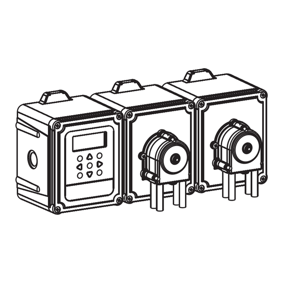
- Page 4 PERATION NGLISH The BrightStar Laundry units, are automatic dosing systems designed for use with commercial washing machines. The units are intended for indoor, fixed installation only. The means of disconnection must be incorporated in the fixed wiring, with an air gap of at least 3mm in each pole. The pumps are initiated by applying signals of between 90V and 240V AC or DC across the corresponding Inputs of the A and B rails on the powerboard.
- Page 5 AFETY RECAUTIONS NGLISH Important Safety Instructions Please read the following precautions carefully before using this equipment. This unit contains high voltage components which, may expose you the risk of electric shock. Do not open the enclosure without isolating the signal and supply sources Do not mount the unit to unstable, irregular or non-vertical surfaces.
- Page 6 Unit Type (cannot be reset) (Formula) Number 00000 BSL10 Customer Name Signal Indication BRIGHTWELL 1-6 on 1 to 6 pump units 1-10 on 7 to 10 pump units 1 2 3 4 5 6 7 8 9 10 Pump Stop Prime...
- Page 7 AYOUT (1-6 OARD POSITION PUMP UNITS NGLISH NGLISH RIGHTSTAR AUNDRY YSTEMS RIGHTSTAR AUNDRY YSTEMS...
- Page 8 AYOUT (7-10 OARD POSITION PUMP UNITS NGLISH NGLISH RIGHTSTAR AUNDRY YSTEMS RIGHTSTAR AUNDRY YSTEMS...
- Page 9 BSL9 = XSP-01-042 BSHL9 = XSP-01-052 BSL10 = XSP-01-043 BSHL10 = XSP-01-053 Supply indicator lamp (5V) Connection to LCD display (under board) BRIGHTWELL G768 ISSUE 3 Connection to POWER BOARD keypad KEYBOARD Ribbon Connection to I/O board Connection to Programming external USB port.
- Page 10 24V DC (36W max) 24V DC Chemical Output Enable (Optional) +24V Ribbon Connection Microboard Machine +24V Interrupt BRIGHTWELL (24V DC) BRIGHTSTAR G766 ISSUE 3 Machine Interrupt Fuse Link (20mm (not fitted) T1A max) B RAIL Resistor Packs (RP1 & 2)
- Page 11 BSL2 = XSP-01-025 BSL3 = XSP-01-026 Supply Buzzer or Lamp BSL4 = XSP-01-026 indicator output for Low lamp Level Alarm BSL5 = XSP-01-027 BSL6 = XSP-01-027 BRIGHTWELL Low Level BRIGHTSTAR G767 ISSUE 3 Alarm +24V Input (x2) BUZZER LAMP LEVEL LEVEL Pump...
- Page 12 L LEVEL Connection SELECT ALARM Microboard Formula Select (Optional) BUZZER 24V supply Lamp or from buzzer mainsboard output BRIGHTWELL (BSL7-10 for Low G776 ISSUE 2 only) Level Alarm 24V IN 24V supply Resistor from Packs RAIL mainsboard (RP1 - 4) PRIM...
- Page 13 AYOUT (7-10 AINSBOARD PUMP UNITS NGLISH Used On: Spare Part No: BSL7-10 XSP-01-035 BSHL7-10 24V DC Output Fuse: Connected to I/O Board 20mm T 1A (Max) Supply from I/O Board BSL Units = 90-265V AC BSHL Units = 230V AC AYOUT (BSHL U ELAY...
- Page 14 NSTALLATION OUNTING NGLISH Fix the unit to a vertical wall using the screws provided. Ensure that the unit is level and positioned no more than 2 metres above the base of the product, which is to be dispensed. x 2 per Enclosure MAXIMUM 2 Metres 132 mm...
- Page 15 NSTALLATION IRING NGLISH In most cases, the solenoids in the host machine will have a common (i.e. their negative terminals are all linked by a common wire). The links LK7 to LK16 (or LK1 to LK6 on 1-6 pump units) can be left in place, and the single (common) wire taken to the B rail. Note: If a signal is applied to Input 2 before Input 1 then the unit will assume that a Pre-wash is not occurring and will ignore subsequent signals to Input 1 until the unit has reset.
- Page 16 NSTALLATION IRING NGLISH For example In some cases, the solenoids in the host machine are common. : The softener solenoid on some Miele machines is not linked via a common wire to the other solenoids. must If this is the case, the signal be isolated from the common B rail on the I/O Board or Driverboard.
- Page 17 NSTALLATION ONNECTING RODUCT NGLISH BSL Units 6x8 Tube Connectors 10 P/k = XSP-07-004 8X11 PVC Tube Cable Ties (100mm) (minimum sized tube) 100P/k = XSP-07-040 30Mtrs = XSP-06-030 To Laundry Machine Take care not to kink delivery or suction tubes Ceramic Weight 4 P/k = XSP-07-035 Sinker Support + Filter 8/10mm...
- Page 18 NSTALLATION ONNECTING RODUCT NGLISH BSHL Units 10x10 Tube Connectors 10 P/k = XSP-07-007 10X16 Reinforced Tube Cable Ties (160mm) (minimum sized tube) 100P/k = XSP-07-041 30Mtrs = XSP-06-041 (Not supplied with unit) Take care not to kink delivery or suction tubes Stiffener Tube 4 P/k = XSP-06-052 To Laundry Machine...
- Page 19 ORMULA ELECT PERATION NGLISH The BrightStar laundry Formula Select module (optional) allows remote selection of up to 20 different wash programs. The Formula Select module can also be used to prime the pumps (see page 39). The desired program must be selected, using the UP and DOWN keys on the module, before beginning the wash cycle.
- Page 20 ORMULA ELECT NSTALLATION NGLISH Fit the module to a suitable surface, in an accessible area, using the self-adhesive Velcro provided. Before fitting, please ensure that the power to the unit has been isolated. Open the lid of the first box. Pass the cable through the gland situated on the bottom of the unit (see page 5) and run it to the vicinity of the Formula Select connection socket on the Powerboard (or I/O Board on 7-10 pump units), see page 9 or 11.
- Page 21 HEMICAL NABLE PERATION NGLISH Once a Chemical Enable module is fitted, it will be automatically acknowledged by the unit, and the relevant pumps (see table below) will be disabled. Pressing the corresponding button on the module can then individually activate the pumps. A light will illuminate to indicate that the chemical will be included in the wash cycle.
- Page 22 HEMICAL NABLE NSTALLATION NGLISH Fit the module to a suitable surface, in an accessible area, using the self-adhesive velcro provided. Before fitting, please ensure that the power to the unit has been isolated. Remove the green connector from the end of the Chemical Enable cable. Open the lid of the first Box. Pass the cable through the gland situated on the bottom of the unit and run it to the vicinity of the Chemical Enable connection socket on the Powerboard (or I/O Board), see page 9 or 11.
- Page 23 For full instruction on the use of the computer software, see the separate instruction booklet (B933). The BrightStar computer software is available for download from or website (www.brightwell.co.uk). Please contact Brightwell Dispensers (tel: +44 1273 513 566 email: brightmail@brightwell.co.uk) for the password to access the download.
- Page 24 ANGUAGE ELECTION It is possible to select the displayed language as English, 00000 BSL10 French, German, Spanish, Dutch, Czech or Polish. BRIGHTWELL TEST From the default screen, press and hold the key for 2 (2 seconds) seconds. The access code screen will then be displayed.
- Page 25 ROGRAM NGLISH FWD/ACCEPT From the default screen, press the key. ENTER CODE TO 00000 BSL10 EDIT SETTINGS BRIGHTWELL ---- Enter the correct four-digit access code using the DOWN FWD/ACCEPT keys to select a number and the key to move on/confirm.
- Page 26 ROGRAMMING SSIGNING ANIFOLDS NGLISH Once the SIGNAL ACCEPTANCE TIME has been set, press MAN 1:---------- MAN 1:---------- MAN 2:---------- MAN 2:1--------- FWD/ACCEPT key to move to the ASSIGNING MAN 3:---------- MAN 3:---------- MANIFOLD screen. OFF P:1234567890 OFF P:-234567890 The BrightStar 7-10 pump software allows the user to have a maximum of three manifolds (flush valves).
- Page 27 ROGRAMMING LUSH ALVE NGLISH The Flush Valve Time, is the time for which the flush valve FLUSH VALVE FLUSH VALVE TIME TIME will open, after the assigned pump is run. 00MINS 00SECS 00MINS 20SECS DOWN Set the flush valve time (00 - 99 Mins) using the keys.
- Page 28 ROGRAMMING LOWRATE NGLISH From the FLUSH VALVE TIME screen (or the ASSIGNING PUMP 1 SET PUMP 1 SPEED MANIFOLD screen if flush valves are not needed), press the FLOWRATE: 0000ml F W D / A C C E P T 080% DATE: 01/01/01 k e y t o m o v e t o t h e P U M P...
- Page 29 ROGRAMMING ELECTING NPUT NGLISH From the PUMP SPEED/FLOWRATE screen, press the PROGRAM 01 PROGRAM 02 SET INPUT 01 SET INPUT 01 FWD/ACCEPT key to move to the INPUT SELECTION screen. see page 34 From this screen the user can select which inputs they wish to assign to which pump.
- Page 30 ROGRAMMING ULSE OUNT NGLISH From the INPUT SELECTION screen, press the PROGRAM 01 PROGRAM 01 SET INPUT 01 SET INPUT 01 FWD/ACCEPT key to move to the PULSE COUNT screen. PULSE COUNT PULSE COUNT The PULSE COUNT setting allows the user to select the number of signal pulses required by the displayed input, before the pump will run.
- Page 31 ROGRAMMING NABLING UMPS NGLISH By default, all of the pumps will initially be set to “DISABLE” on PROGRAM 01 SET INPUT 02 all of the inputs. SET PUMP 01 DISABLE Use the FWD/ACCEPT BACK keys to select the pump that you wish to run when a signal is received on the selected input.
- Page 32 ROGRAMMING OSAGE NGLISH If a flow rate has been set for the pump, the unit will INPUT2/PUMP4 DOSAGE automatically ask for a dosage to be selected. 00000ml The dosage is the volume of product (in ml), which you wish to be dispensed into the host machine, during a single cycle.
- Page 33 ROGRAMMING ESET ONDITION NGLISH The BrightStar Laundry unit, will allow the user to set the SET RESET TO condition under which the unit will reset. LAST PUMP This condition defaults to LAST PUMP, but has three possibilities: LAST PUMP SET RESET TO The unit will re-set after the last pump (usually the fabric FEATURE OFF softener) has run.
- Page 34 Note: If the unit is left in any part of the PROGRAM MODE, with no keys pressed for 30 mins, it will automatically save the changes 00000 BSL10 and revert to operational mode. BRIGHTWELL RIGHTSTAR AUNDRY YSTEMS RIGHTSTAR AUNDRY...
- Page 35 ROGRAMMING REATING DDITIONAL ROGRAMS NGLISH Enter the program as described on page 24. PROGRAM 01 PROGRAM 02 SET INPUT 01 SET INPUT 01 PROGRAM From the INPUT SELECTION screen, Press the key to increment the program number. Enter the parameters for additional programs in the same manor as before (see page 28 to 33).
- Page 36 ROGRAMMING Deleting an Existing Program NGLISH PROGRAM From the Input Selection screen, press the key to PROGRAM 01 INPUT 01 increment the program number to the one you wish to delete. BACK PROGRAM Press the keys simultaneously. DOWN Using the keys, select whether to delete the PROGRAM 03 current program or ALL programs.
- Page 37 PROGRAM 01 PUMP 10 PUMP 10 If a Flowrate has been set instead of a Pump Speed, the unit 00MINS 00SECS 00000 will display TOTAL FLOW QUANTITY instead of RUN TIME. 00000 BSL10 BRIGHTWELL RIGHTSTAR AUNDRY YSTEMS RIGHTSTAR AUNDRY YSTEMS...
- Page 38 ELAY NGLISH The BrightStar unit will default to its “Standard” operational 00000 BSL10 mode. BRIGHTWELL However if the host machine is “Intelligent” (ie. computer (2 seconds) controlled), it may be preferable to use the RELAY mode ENTER CODE TO (Descriptions of both of the unit’s operational modes can be...
- Page 39 ROGRAMMING ELAY NGLISH Access the program mode by entering the four-digit security BSL10 RELAY MODE code (see page 24). Assign the pumps to the required manifolds (see page 25). FWD/ACCEPT Press the key to confirm and move to the next screen.
- Page 40 ROM THE NGLISH PRIME To prime the pumps from the Keypad, press the key to 00000 BSL10 display the Prime Mode screen. BRIGHTWELL DOWN Use the keys to select the pump that you wish to prime. PRIME MODE PRIME MODE PROGRAM...
- Page 41 NGLISH All pumps can be individually stopped from the keypad. 00000 BSL10 PUMP STOP Press the key to display the PUMP STOP MODE BRIGHTWELL screen. FOWARD/ACCEPT BACK Use the keys to highlight the pump that needs to be turned off/on.
- Page 42 NGLISH In order to check that all of the required inputs are receiving 00000 BSL10 signals (and to test for inputs which are receiving multiple BRIGHTWELL signals), the BrightStar software provides a PULSE TEST screen. To Access: IP1=00 2=00 3=00...
- Page 43 ELECT NGLISH For use with computer controlled (intelligent) host machines 00000 BSL10 only, the Auto Formula Select mode allows automatic selection BRIGHTWELL of programs (formulas) without the need for a Formula Select module. To Activate: 00000 BSL10 AUTO FORMULA SELECT MODE...
- Page 44 INPUT 01 the next screen. The Delay will start after the operation of the corresponding Input. 00000 BSL10 BRIGHTWELL LUSH ALVE AFETY PTIONAL When using the unit in conjunction with a manifold, it is possible NO WATER...
- Page 45 & P INCL ISABLING RIME NGLISH To access the TEST MODE, first de-power the unit. TEST Then, while holding down the key, power the unit back When the unit has initiated, it will be in TEST MODE. To check the keypad is functioning correctly: 00000 BSL10 TEST...
- Page 46 00000 BSL10 information by linking the unit to a laptop (see page 22). BRIGHTWELL The BrightStar unit also allows for the connection of a suitable printer (see page 46) to enable direct printing of the unit settings and cycle counters.
- Page 47 NCILLARIES NGLISH Laundry Manifold XLM-8-24 Part number = (24V, 8mm connectors) XLM-8-24SS Part number = (24V, 8mm connectors + Safety stop) XLM-8-NS Part number = (24V, 8mm connectors) XLM-10-24 Part number = (24V, 10mm connectors) XLM-10-24SS Part number = (24V, 10mm connectors + Safety stop) XLM-10-NS Part number = (No solenoid, 10mm connectors)
- Page 48 LOSSARY NGLISH Signal Acceptance - Length of time that a signal must be present on an Input before it is acknowledged. Flush Valve - 24V DC output to control a Flush Solenoid (maximum 36W). This output is active throughout the operation of any pump.
- Page 49 ABLE DES ATIERES RAN AIS Ç Fonctionnement........50 Sélection des formules (suite): Consignes de sécurité......51 Consignes de sécurité…....…65 Liste de contrôle pour l'emballage...51 Agencement………...……….65 Agencement de l'unité Installation……....……….66 Externe..........52 Activation des produits chimiques: Clavier et écran...……..……..52 Fonctionnement....………67 Position des cartes (1-6 pompes)...53 Consignes de sécurité…..…67 Position des cartes (7-10 pompes).54 Agencement...……………….67...
- Page 50 A partir de l'unité………....….86 directe de toute unité BrightStar à partir d'un ordinateur portable, est disponible sur demande. A partir de la sélection des formule..86 Email: brightmail@brightwell.co.uk Arrêt des pompes.........87 RIGHTSTAR AUNDRY YSTEMS RIGHTSTAR AUNDRY YSTEMS...
- Page 51 ONCTIONNEMENT RAN AIS Ç Les unités BrightStar pour blanchisseries sont des systèmes de dosage automatiques conçus pour utilisation avec des machines à laver commerciales. Les unités sont conçues pour une installation fixe à l'intérieur seulement. Le moyen de sectionnement doit être incorporé...
- Page 52 ONSIGNES DE S CURIT É É RAN AIS Ç Importantes consignes de sécurité Veuillez lire attentivement les consignes suivantes avant d'utiliser cet équipement. Cette unité contient des composants haute tension qui peuvent vous exposer au risque de choc électrique. N'ouvrez pas le boîtier sans isoler les sources d'alimentation et de signaux.
- Page 53 (remise à zéro impossible) actuel (Formule) Nom du client 00000 BSL10 1.Indication des signaux. BRIGHTWELL 1-6 sur les unités à 1-6 pompes, 1-10 sur les unités à 7-10 pompes Arrêt de la pompe 1 2 3 4 5 6 7 8 9 10 Amorçage...
- Page 54 GENCEMENT DE L UNIT (1-6 RAN AIS É OSITION DES CARTES POMPES Ç RIGHTSTAR AUNDRY YSTEMS RIGHTSTAR AUNDRY YSTEMS...
- Page 55 GENCEMENT DE L UNIT (7-10 É OSITION DES CARTES POMPES RIGHTSTAR AUNDRY YSTEMS RIGHTSTAR AUNDRY YSTEMS...
- Page 56 BSL10 = XSP-01-043 BSHL7 = XSP-01-050 BSHL8 = XSP-01-051 BSHL9 = XSP-01-052 BSHL10 = XSP-01-053 Voyant d'alimentation (5V) Connexion affichage à cristaux liquides (sous la carte) BRIGHTWELL G768 ISSUE 3 Connexion POWER BOARD clavier KEYBOARD Connexion par ruban à la carte d'E/S...
- Page 57 Activation des produits chimiques Sortie (en option) 24V CC Ruban carte à +24V microprocesseur Interruption +24V de la machine BRIGHTWELL (24V CC) BRIGHTSTAR G766 ISSUE 3 Broche d Fusible interruption 20mm T1A de la machine (Maxi) (pas montée) B RAIL...
- Page 58 Sortie voyant ou BSL3 = XSP-01-026 Voyant ronfleur pour BSL4 = XSP-01-026 d'alimentation alarme niveau bas BSL5 = XSP-01-027 BSL6 = XSP-01-027 Entrée alarme niveau bas(x2) BRIGHTWELL BRIGHTSTAR G767 ISSUE 3 +24V BUZZER LAMP LEVEL LEVEL Sorties pompe (x3) Pilote Darlington N°...
- Page 59 Alimentation (en option) BUZZER 24V à partir de la carte Sortie voyant secteur ou ronfleur (BSL7-10 pour alarme BRIGHTWELL seulement) niveau bas G776 ISSUE 2 24V IN Alimentation Resistor 24V à partir Packs RAIL de la carte (RP1 - 4)
- Page 60 GENCEMENT DE L UNIT 7-10 É ARTE SECTEUR UNIT S POMPES É À Utilisé avec: N° de pièce de BSL7-10 rechange: BSHL7-10 XSP-01-035 Sortie 24V CC Fusible: Connecté à la 20mm T 1A (Maxi) carte E/S Alimentation à partir de la carte d'E/S Unités BSL = 90-265V CA Unités BSHL = 230V CA...
- Page 61 NSTALLATION ONTAGE RAN AIS Ç Fixez l'unité à un mur vertical à l'aide des vis fournies. Veillez à ce que l'unité soit horizontale et positionnée pas plus de 2 mètres au-dessus de la base du produit qui doit être distribué. X 2 par boîtier 2 mètres MAXIMUM...
- Page 62 NSTALLATION BLAGE RAN AIS Ç Â Dans la plupart des cas, les solénoïdes dans la machine hôte sont communs (c'est-à-dire que leurs bornes négatives sont toutes reliées par un fil commun). Les broches LK7 à LK16 (ou LK1 à LK6 sur les unités à 1-6 pompes) peuvent être laissées en place, et le fil unique (commun) amené...
- Page 63 NSTALLATION BLAGE RAN AIS Ç Â Dans certains cas, les solénoïdes dans la machine hôte ne sont pas communs. Par exemple : Le solénoïde produit assouplissant sur certaines machines Miele n'est pas relié par l'intermédiaire d'un fil commun aux autres solénoïdes. Si cela est le cas, le signal doit être isolé...
- Page 64 NSTALLATION ONNEXION PRODUIT RAN AIS Ç Unités BSL 6x8 raccords de tube 10 P/k = XSP-07-004 8X11 PVC Tube Serre-câble (100mm) (tube de taille minimum) 100P/k = XSP-07-040 30Mtrs = XSP-06-030 Vers machine Veillez à ne pas entortiller les tubes d'aspiration ou de refoulement Poids céramique 4 P/k = XSP-07-035...
- Page 65 NSTALLATION ONNEXION PRODUIT RAN AIS Ç Unités BSL 10x10 raccords de tube 10 P/k = XSP-07-007 10X16 Tube renforcé Serre-câble (160mm) (tube de taille minimum) 100P/k = XSP-07-041 30Mtrs = XSP-06-041 (non fourni avec l'unité) Veillez à ne pas entortiller les tubes d'aspiration ou de refoulement Tube raidisseur 4 P/k = XSP-06-052...
- Page 66 LECTION DES FORMULES É ONCTIONNEMENT RAN AIS Ç Le module Sélection des formules pour blanchisseries BrightStar (en option) permet la sélection à distance de jusqu'à 20 programmes de lavage différents. Le module Sélection des formules peut également être utilisé pour amorcer les pompes (voir page 86). Le programme désiré...
- Page 67 LECTION DES FORMULES É NSTALLATION RAN AIS Ç Montez le module sur une surface appropriée, dans un endroit accessible, à l'aide du Velcro autocollant fourni. Avant le montage, veillez à ce que l'alimentation de l'unité ait été isolée. Ouvrez le couvercle de la première boîte. Passez le câble dans le presse-étoupe situé sur le fond de l'unité (voir page 52) et amenez-le à...
- Page 68 CTIVATION DES PRODUITS CHIMIQUES ONCTIONNEMENT Une fois qu'un module d'activation des produits chimiques est monté, l'unité confirme automatiquement, et les pompes appropriées (voir le tableau ci-dessous) seront désactivées. Un appui sur le bouton correspondant du module peut ensuite activer individuellement les pompes. Un voyant s'allumera pour indiquer que le produit chimique sera inclus dans le cycle de lavage.
- Page 69 CTIVATION DES PRODUITS CHIMIQUES NSTALLATION Montez le module sur une surface appropriée, dans un endroit accessible, à l'aide du Velcro autocollant fourni. Avant le montage, veillez à ce que l'alimentation de l'unité ait été isolée. Retirez le connecteur vert de l'extrémité du câble d'activation des produits chimiques. Ouvrez le couvercle de la première boîte.
- Page 70 Pour des instructions complètes sur l'utilisation du logiciel informatique, voir le livret d'instructions séparé (B933). Le logiciel informatique BrightStar est disponible pour téléchargement à partir de notre site web. Veuillez contacter Brightwell Dispensers pour obtenir le mot de passe permettant d'accéder au téléchargement. (tél.: +44 1273 513 566 email: brightmail@brightwell.co.uk)
- Page 71 LECTION DE LA LANGUE É Il est possible de sélectionner la langue affichée, à savoir 00000 BSL10 anglais, français, allemand, espagnol, hollandais, tchèque ou BRIGHTWELL polonais. (2 secondes) A partir de l'écran par défaut, appuyez et maintenez la touche TEST enfoncée pendant 2 secondes.
- Page 72 Ç A partir de l'écran par défaut, appuyez sur la touche INDIC. D`ACCESS 00000 BSL10 EDITEZ REGLAGE AVANCE/ACCEPTATION BRIGHTWELL ---- Entrez le code d'accès correct à quatre chiffres en utilisant les touches HAUT pour sélectionner un numéro et la touche AVANCE/ACCEPTATION pour continuer/confirmer.
- Page 73 ROGRAMMATION FFECTATION DES FLUSH MANIFOLD Une fois que le TEMPS D'ACCEPTATION DE SIGNAL aura été MAN 1:---------- MAN 1:---------- MAN 2:---------- MAN 2:1--------- réglé, appuyez sur la touche AVANCE/ACCEPTATION pour MAN 3:---------- MAN 3:---------- passer à l'écran AFFECTATION DES FLUSH MANIFOLD. OFF P:1234567890 OFF P:-234567890 Le logiciel 7-10 pompes BrightStar permet à...
- Page 74 ROGRAMMATION ALVE DE RINCAGE DUREE RAN AIS Ç Le Valve de rincage - duree est le temps pendant lequel l'valve VALVE DE RINCAGE VALVE DE RINCAGE DUREE DUREE de rincage (électro-vanne) restera ouverte après que l'on ait fait fonctionner la pompe affectée. 00MINS 00SECS 00MINS 20SECS Réglez le Temps (duree) valve de rincage (00 99 minutes) à...
- Page 75 ROGRAMMATION EBIT RAN AIS Ç A partir de l'écran VALVE DE RINCAGE - DUREE (ou de POMPE 1 REG POMPE 1 VITESSE l'écran AFFECTATION DES BLOCS si les valves de rincage ne DEBIT: 0000ml sont pas nécessaires), appuyez sur la touche 080% DATE: 01/01/01 AVANCE/ACCEPTATION...
- Page 76 ROGRAMMATION LECTION DES ENTR ES RAN AIS É É Ç A partir de l'écran VITESSE DE POMPE/DEBIT, appuyez sur la PROGRAMME 01 PROGRAMMA 02 REG ENTREE 01 REG ENTREE 01 touche AVANCE/ACCEPTATION pour passer à l'écran SELECTION DES ENTREES. (voir page 81) A partir de cet écran, l'utilisateur peut sélectionner quelles entrées ils souhaitent affecter à...
- Page 77 ROGRAMMATION OMPTAGE D IMPULSIONS RAN AIS Ç A partir de l'écran SELECTION DES ENTREES, appuyez sur PROGRAMMA 01 PROGRAMMA 01 REG ENTREE 01 REG ENTREE 01 AVANCE/ACCEPTATION la touche pour passer à l'écran COMPTE IMPULSION COMPTE IMPULSION COMPTAGE D'IMPULSIONS. TOUTES Le réglage COMPTAGE D'IMPULSIONS permet à...
- Page 78 ROGRAMMATION ALIDATION DES POMPES RAN AIS Ç Par défaut, l'ensemble des pompes seront initialement réglées PROGRAMMA 01 REG ENTREE 02 sur “DESACTIVATION” sur l'ensemble des entrées. REG POMPEP 01 MISE HORS SERVIC Utilisez les touches AVANCE/ACCEPTATION RETOUR pour sélectionner la pompe que vous souhaitez faire fonctionner lorsqu'un signal est reçu sur l'entrée sélectionnée.
- Page 79 ROGRAMMATION OSAGE RAN AIS Ç Si un débit a été réglé pour la pompe, l'unité demandera ENTREE2/POMPE4 DOSAGE automatiquement qu'un dosage soit sélectionné. 00000ml Le dosage est le volume de produit (en ml) que vous souhaitez voir distribué dans la machine hôte pendant un cycle unique. ENTREE2/POMPE4 Réglage: DOSAGE...
- Page 80 ROGRAMMATION É TAT DE REMISE À É Z RO RAN AIS Ç L'unité pour blanchisseries BrightStar permettra à l'utilisateur REINITIALISATION de régler la condition dans laquelle l'unité sera remise à zéro. DERNIERE POMPE La condition par défaut est DERNIERE POMPE, mais il y a trois possibilités: DERNIERE POMPE REINITIALISATION...
- Page 81 Nota: 00000 BSL10 Si l'unité est laissée à tout moment pendant le MODE DE BRIGHTWELL PROGRAMMATION, sans que l'on appuie sur une touche pendant 30 minutes, elle enregistrera automatiquement les changements et repassera au mode de fonctionnement.
- Page 82 ROGRAMMATION R ATION DE PROGRAMMES SUPPL MENTAIRES É É Entrez le programme comme décrit à la page 71. PROGRAMMA 01 PROGRAMMA 02 REG ENTREE 01 REG ENTREE 01 A partir de l'écran Selection DES ENTREES, appuyez sur la touche PROGRAMME pour incrémenter le numéro de programme.
- Page 83 ROGRAMMATION UPPRESSION UN PROGRAMME EXISTANT A partir de l'écran SELECTION DES ENTREES, appuyez sur PROGRAM 01 INPUT 01 la touche PROGRAMME pour faire passer le numéro de programme à celui que vous souhaitez supprimer. Appuyez simultanément sur les touches RETOUR PROGRAMME PROGRAMMA 03 REG ENTREE 01...
- Page 84 Dosage de produit chimique = 50 000 litres Nota: Si un débit a été réglé au lieu d'une vitesse de pompe, l'unité affichera DEBIT TOTAL au lieu de TEMPS DE MARCHE TOTAL. 00000 BSL10 BRIGHTWELL RIGHTSTAR AUNDRY YSTEMS RIGHTSTAR AUNDRY...
- Page 85 RAN AIS È Ç L'unité BrightStar retournera par défaut à son mode de 00000 BSL10 fonctionnement “standard”. BRIGHTWELL Toutefois, si la machine hôte est “intelligente” (c'est-à-dire (2 secondes) commandée par ordinateur), il peut être préférable d'utiliser le mode RELAIS. INDIC. D`ACCESS...
- Page 86 ROGRAMMATION ODE RELAIS RAN AIS Ç Accédez au mode de programmation en entrant le code de BSL10 MODE RELAIS sécurité à quatre chiffres (voir page 71). Affectez les pompes aux blocs requis (voir page 72). Appuyez sur la touche AVANCE/ACCEPTATION pour confirmer et passer à...
- Page 87 Ç Pour amorcer les pompes à partir du clavier, appuyez sur la 00000 BSL10 touche AMORCAGE pour afficher l'écran mode d'amorçage. BRIGHTWELL Utilisez les touches HAUT pour sélectionner la pompe que vous souhaitez amorcer. MODE DE REMPLISS MODE DE REMPLISS...
- Page 88 Toutes les pompes peuvent être individuellement arrêtées à 00000 BSL10 partir du clavier. Appuyez sur la touche ARRET DES POMPES BRIGHTWELL pour afficher l'écran MODE D'ARRET DES POMPES. Utilisez les touches AVANCE/ACCEPTATION RETOUR pour mettre en évidence la pompe qui doit être mise hors...
- Page 89 Ç Afin de vérifier que l'ensemble des entrées requises reçoivent 00000 BSL10 des signaux (et pour détecter les entrées qui reçoivent BRIGHTWELL plusieurs signaux), le logiciel BrightStar fournit un écran TEST DES IMPULSIONS. Pour y accéder: ENT=00 2=00 3=00 ENT=00 2=00 3=00 A partir de l'écran par défaut, appuyez sur la touche...
- Page 90 RAN AIS Ç Pour utilisation avec les machines hôtes commandées par 00000 BSL10 ordinateur (intelligentes) seulement, le mode sélection BRIGHTWELL automatique des formules permet la sélection automatique des programmes (formules) sans avoir besoin d'un module de sélection des formules. 00000 BSL10...
- Page 91 à l'écran suivant. La interruption commencera après le fonctionnement de 00000 BSL10 l'entrée correspondante. BRIGHTWELL RR T DE S CURIT VALVE DE RINCAGE Ê É É EN OPTION Lors de l'utilisation de l'unité conjointement avec un bloc, il est PAS D`EAU possible de connecter un dispositif de détection d'eau (détails...
- Page 92 ODE TEST ’ Y COMPRIS LA D ACTIVATION DE LA NEUTRALISATION DES POMPES ET DE L AMOR AGE É Ç Pour accéder au MODE TEST, mettez d'abord l'unité hors tension. Ensuite, tout en maintenant la touche TEST enfoncée, remettez l'unité sous tension. Lorsque l'unité se sera déclenchée, elle sera en MODE TEST.
- Page 93 L'unité BrightStar, qui permet non seulement d'imprimer des 00000 BSL10 informations relatives à l'utilisation des produits et au réglage BRIGHTWELL de l'unité lorsque reliée à un ordinateur portable (voir page 69), peut également être connectée à une imprimante appropriée (voir page 93) pour permettre d'imprimer directement les réglages et les compteurs de cycles de l'unité.
- Page 94 CCESSOIRES RAN AIS Ç Blocs pour blanchisseries Numéro de la pièce = XLM-8-24 (24V, raccords de 8mm) Numéro de la pièce = XLM-8-24SS (24V, raccords de 8mm + arrêt de sécurité) Numéro de la pièce = XLM-8-NS (24V, raccords de 8mm) Numéro de la pièce = XLM-10-24 (24V, 10mm connectors)
- Page 95 LOSSAIRE RAN AIS Ç Acceptation de signal - Temps pendant lequel un signal doit être présent sur une entrée avant qu'il n'en soit accusé réception. Électro-vanne (Valve de rincage) Sortie 24V CC pour contrôler une électro-valve (36W maximum). Cette sortie est active pendant tout le fonctionnement de toute pompe.
- Page 96 NHALT EUTSCH Betrieb............97 Formelauswahl (Forts): Sicherheitsvorkehrungen......98 Sicherheitsvorkehrungen....112 Paketprüfliste..........98 Auslegung……………....……112 Auslegung der Einheit: Installation……………....……113 Extern..........99 Chemikalienaktivierung: Tastatur und Bildschirm..………99 Betrieb……..…..……..……114 Platinenposition (1-6 Pumpen)…..100 Sicherheitsvorkehrungen..….114 Platinenposition (7-10 Pumpen)..101 Auslegung…..…..……………114 Mikroplatine……..……………..102 Installation………....…………115 Stromversorgungsplatine..……..…103 Programmierung: Treiberplatine………….……..……104 Von einem Laptop…..….....….116 Eingangs-/Ausgangsplatine…..…105 Drucktasten........117 Netzplatine........106 Schlüssel für die Betriebsanleitung...117 Relaisplatine........106 Sprachauswahl........117 Installation:...
- Page 97 Vorpumpen der Pumpen: Die BrightStar Computer-Software, Von der Einheit…...…..…..……133 die die direkte Programmierung aller BrightStar Geräte von einem Von der Formelauswahl……..133 Laptop ermöglicht, ist auf Anfrage erhältlich. Stoppen der Pumpen.........134 E-mail: ANSICHT-Modus........134 brightmail@brightwell.co.uk Impulstest…………………..……..………135 RIGHTSTAR AUNDRY YSTEMS RIGHTSTAR AUNDRY YSTEMS...
- Page 98 ETRIEB EUTSCH Die BrightStar Waschsysteme sind automatische Dosiersysteme für Waschmaschinen für den gewerblichen Einsatz. Die Systeme sind nur zur festen Installation und zur Verwendung in Gebäuden gedacht. Der Stromunterbrecher ist in der festen Verkabelung zu integrieren, wobei ein Abstand von mindestens 3 mm an jedem Pol vorhanden sein muss. Die Pumpeninbetriebnahme erfolgt durch Anlegen von Signalen zwischen 90V und 240V Wechsel- oder Gleichstrom an den jeweiligen Eingängen der Schienen A und B an der Stromversorgungsplatine.
- Page 99 ICHERHEITSVORKEHRUNGEN EUTSCH Wichtige Sicherheitsanweisungen Vor Verwendung dieser Ausrüstung bitte diese Sicherheitsanweisungen sorgfältig lesen. Diese Einheit enthält Hochspannungsteile, durch die Sie einen Elektroschock erleiden könnten. Das Gehäuse nicht ohne Abschaltung der Signal- und Versorgungsquellen öffnen. Die Einheit nicht auf instabilen, unregelmäßigen oder nichtvertikalen Oberflächen aufbauen. Keine schweren Teile oben auf die Einheit setzen.
- Page 100 Gesamteinheitzyklen Aktuelle Programmnummer Einheitentyp (können nicht rückgesetzt werden) (Formelnummer) 00000 BSL10 Kundenname Signalangabe. BRIGHTWELL 1-6 bei Einheiten mit 1-6 Pumpen 1-10 bei Einheiten mit 7-10 Pumpen 1 2 3 4 5 6 7 8 9 10 Pumpenstopp Vorpumpen Zurück Vor/Eingabe...
- Page 101 USLEGUNG DER INHEIT (1-6 P LATINENPOSITION UMPEN RIGHTSTAR AUNDRY YSTEMS RIGHTSTAR AUNDRY YSTEMS...
- Page 102 USLEGUNG DER INHEIT (7-10 P LATINENPOSITION UMPEN RIGHTSTAR AUNDRY YSTEMS RIGHTSTAR AUNDRY YSTEMS...
- Page 103 BSL9 = XSP-01-042 BSL10 = XSP-01-043 BSHL7 = XSP-01-050 BSHL8 = XSP-01-051 BSHL9 = XSP-01-052 BSHL10 = XSP-01-053 Stromversorgungskontrollleuchte (5V) Anschluss an LCD-Display (unter der Platine) BRIGHTWELL G768 ISSUE 3 Anschluss POWER BOARD an Tastatur KEYBOARD Bandkabelanschluss E/A-Platine Anschluss Programmierkopf an externen USB-Port.
- Page 104 Spülventil Gleichstrom (36W max.) Gleichstrom- ausgang Chemikalien- aktivierung (optional) +24V Bandkabel- anschluss Mikroplatine Maschinenun- +24V terbrechung BRIGHTWELL (24V BRIGHTSTAR Gleichstrom) G766 ISSUE 3 Maschinenunterbre- Sicherung chungsverbindung (20 mm (nicht angebracht) T1A max.) B RAIL Widerstand- spackungen (RP1 und 2) Schiene B (Negativ) (Eingänge 1 - 6)
- Page 105 BSL1-6 BSL1 = XSP-01-025 BSL2 = XSP-01-025 Stromversorgungskontrollleuchte BSL3 = XSP-01-026 Summer- oder BSL4 = XSP-01-026 Lampenausgang für Niedrigpegelalarmsignal BSL5 = XSP-01-027 BSL6 = XSP-01-027 BRIGHTWELL Niedrigpegel BRIGHTSTAR G767 ISSUE 3 alarmeingang +24V (x2) BUZZER LAMP LEVEL LEVEL Darlington- Treiber...
- Page 106 SELECT ALARM anschluss an Mikroplatine Formelauswahl 24V Versorgung (Zusatz- BUZZER von der ausstattung) Netzplatine (nur BSL7-10) Summer- oder Lampenausgang BRIGHTWELL für G776 ISSUE 2 Niedrigpegel- 24V IN alarmsignal Widerstand- RAIL 24V Versorgung spackungen PRIM von der (RP1 - 4) Netzplatine...
- Page 107 USLEGUNG DER INHEIT 7-10) ETZPLATINE UMPENANLAGEN Verwendet am: Ersatzteilnummer: BSL7-10 XSP-01-035 BSHL7-10 24V Gleichstrom Ausgang Anschluss an E/A-Platine Sicherung: 20 mm T 1A (Max) Versorgung von E/A-Platine BSL-Einheiten = 90-265V Wechselstrom BSHL- Einheiten = 230V Wechselstrom USLEGUNG DER INHEIT (BSHL- A ELAISPLATINE NLAGEN Verwendet am:...
- Page 108 NSTALLATION UFBAU EUTSCH Die Einheit mittels der bereitgestellten Schrauben an einer vertikalen Wand montieren. Darauf achten, das die Einheit waagerecht und nicht mehr als 2 Meter über dem Fuß der Produktausgabe montiert ist. X 2 pro Gehäuse MAXIMAL 2 Meter 132 mm 169 mm RIGHTSTAR...
- Page 109 NSTALLATION ERKABELUNG EUTSCH In den meisten Fällen haben die Magnetventile in der Zentralmaschine einen gemeinsam Anschluss, (d. h. ihre negativen Klemmen sind mit einem gemeinsamen Draht verbunden). Die Verbindungen LK7 zu LK16 (oder LK1 zu LK6 an den Einheiten mit 1-6 Pumpen) können dort bleiben, und der einzelne (gemeinsame Draht) kann zur Schiene B geführt werden.
- Page 110 NSTALLATION ERKABELUNG EUTSCH In einigen Fällen sind die Magnetventile in der Zentralmaschine nicht gemeinsam angeschlossen. Beispiel: Das Weichspülmittel-Magnetventil bei einigen Miele-Maschinen ist nicht über einem gemeinsamen Draht mit den anderen Magnetventilen verbunden. Sollte dies der Fall sein, ist das Signal von der gemeinsamen Schiene B an der E/A-Platine oder Treiberplatine zu unterbrechen.
- Page 111 NSTALLATION (BSL-E RODUKTANSCHLUSS INHEITEN EUTSCH 6x8 Schlauchverbindungen 10 P/k = XSP-07-004 8X11 PVC Tube Kabelbinder (100 mm) (Schlauch mit Mindestgröße) 100P/k = XSP-07-040 30Mtrs = XSP-06-030 Zur Waschmaschine Achten Sie darauf, die Saug- oder Zufuhrschläuche nicht zu knicken Keramikgewicht 4 P/k = XSP-07-035 Gewichtstütze und Filter 8/10 mm 4 P/k = XSP-07-032...
- Page 112 NSTALLATION (BSHL-E RODUKTANSCHLUSS INHEITEN EUTSCH 10x10 Schlauchverbindungen 10 P/k = XSP-07-007 10X16 Verstärkter Schlauch Kabelhalter (160mm) 30Mtrs = XSP-06-041 100P/k = XSP-07-041 (wird nicht mit der Einheit geliefert) Achten Sie darauf, die Saug- oder Zufuhrschläuche nicht zu knicken Versteifungsschlauch 4 P/k = XSP-06-052 Zur Waschmaschine Gewichtstütze und Filter 8/10 mm...
- Page 113 ORMELAUSWAHL ETRIEB EUTSCH Das BrightStar Waschmodul Formelauswahl (optional) ermöglicht die Fernauswahl von max. 20 verschiedenen Waschprogrammen. Das Modul Formelauswahl kann auch zum Vorpumpen der Pumpen verwendet werden (s. Seite 133). Das gewünschte Programm muss unter Betätigung der Modultasten AUF und AB vor Beginn des Waschzyklus gewählt werden.
- Page 114 ORMELAUSWAHL NSTALLATION EUTSCH Das Modul an einer geeigneten Oberfläche mit Hilfe des mitgelieferten Klebebands (Klettverschlussband) in einem zugänglichen Bereich anbringen. Vor der Montage sicherstellen, dass der Strom zur Einheit unterbrochen worden ist. Den Deckel des ersten Kastens öffnen. Das Kabel durch die erste Stopfbüchse an der Unterseite der Einheit hindurch führen (s.
- Page 115 HEMIKALIENAKTIVIERUNG ETRIEB EUTSCH Nach Anbringen des Chemikalienaktivierungsmoduls wird die Einheit dies automatisch bestätigen und die entsprechenden Pumpen (s. Tabelle unten) werden deaktiviert. Durch Drücken der entsprechenden Modultaste können dann die einzelnen Pumpen aktiviert werden. Eine Lampe erleuchtet zur Anzeige, dass die Chemikalie im Waschzyklus enthalten ist. Bei versehentlicher Auswahl kann die Chemikalie durch nochmaliges Drücken der Taste deaktiviert werden.
- Page 116 HEMIKALIENAKTIVIERUNG NSTALLATION EUTSCH Das Modul an einer geeigneten Oberfläche in einem zugänglichen Bereich unter Verwendung des bereitgestellten Klebbands (Velcro) anbringen. Vor der Montage sicherstellen, dass der Strom zur Einheit unterbrochen worden ist. Den grünen Anschluss vom Ende des Kabels der Chemikalienaktivierung entfernen. Den Deckel des ersten Kastens öffnen.
- Page 117 Vollständige Angaben zur Verwendung der Computer-Software entnehmen Sie bitte dem separaten Handbuch (B933). Die BrightStar Computer-Software ist zum Herunterladen von unserer Website erhältlich. Bitte wenden Sie sich an Brightwell Dispensers, um ein Passwort zu erhalten, mit dem Sie die Software herunterladen können. (Tel: +44 1273 513 566 email: brightmail@brightwell.co.uk) RIGHTSTAR...
- Page 118 Bildschirm ROGRAMMIERUNG PRACHAUSWAHL Es kann unter den folgenden Sprachen gewählt werden: 00000 BSL10 Englisch, Französisch, Deutsch, Spanisch, Holländisch, BRIGHTWELL Tschechisch oder Polnisch. (2 Sekunden) VomDie Taste TEST bei angezeigtem Standardbildschirmdie 2 Sekunden lang drücken. Dann erscheint der Bildschirm des Zugriffscode.
- Page 119 V O R / E I N G A B E b e i a n g e z e i g t e m 00000 BSL10 E/G EINSTELLUNG Standardbildschirmdie drücken. BRIGHTWELL ---- Den richtigen vierstelligen Zugriffscode eingeben, die Tasten zur Auswahl einer Nummer und die Taste VOR/EINGABE , um weiterzugehen/zu bestätigen, drücken.
- Page 120 ROGRAMMIERUNG ERTEILERZUTEILUNG EUTSCH Nach Einstellung der SIGNALANNAHMEZEIT drücken Sie die MAN 1:---------- MAN 1:---------- MAN 2:---------- MAN 2:1--------- Taste VOR/EINGABE , um zum Bildschirm VERTEILER MAN 3:---------- MAN 3:---------- ZUTEILEN zu gehen. AUS P:1234567890 AUS P:-234567890 Die BrightStar 7-10Software für 7-10 Pumpen bietet dem Anwender maximal drei Verteiler (Spülventile).
- Page 121 ROGRAMMIERUNG P LVENTILZEIT EUTSCH Ü Die SPÜLVENTILZEIT ist die Zeitdauer, während der das SPULVENTIL SPULVENTIL ZEIT ZEIT Spülventil geöffnet ist, nachdem die zugeteilte Pumpe betrieben wird. 00MINS 00SECS 00MINS 20SECS Die Spülventilzeit (00 - 99 Minuten) mit Hilfe der Tasten einstellen.
- Page 122 ROGRAMMIERUNG INSTELLUNG DER RDERMENGE DER UMPE Ö Auf dem Bildschirm SPÜLVENTILZEIT (oder dem Bildschirm PUMPE 1 PUMPE 1 GESCHWINDIGKEIT VERTEILER ZUTEILEN, falls Spülventile nicht erforderlich DURCHSATZ: 0000ml sind), die Taste VOR/EINGABE drücken, um zum Bildschirm 080% DATUM: 01/01/01 PUMPENDREHZAHL/FÖRDERMENGE zu gehen. Die BrightStar Software ermöglicht dem Anwender die PUMPE 1 Programmierung jeder Pumpe mit einer Fördermenge...
- Page 123 ROGRAMMIERUNG INGANGSAUSWAH EUTSCH Auf dem Bildschirm PUMPENDREHZAHL/FÖRDERMENGE PROGRAMM 01 PROGRAMM 02 EINGANG 01 EINGANG 01 die Taste VOR/EINGABE drücken, um zum Bildschirm EINGANGSAUSWAHL zu gehen. s. Seite Auf diesem Bildschirm kann der Anwender wählen, welche Eingänge welcher Pumpe zugeteilt werden sollen. PROGRAMM 01 EINGANG 02 BrightStar Einheiten haben maximal:...
- Page 124 ROGRAMMIERUNG MPULSZ HLUNG EUTSCH Ä Auf dem Bildschirm EINGANGSAUSWAHL die Taste PROGRAMM 01 PROGRAMM 01 EINGANG 02 EINGANG 02 V O R / E I N G A B E d r ü c k e n , u m z u m B i l d s c h i r m PULS ZAHLEN PULS ZAHLEN IMPULSZÄHLER zu gehen.
- Page 125 ROGRAMMIERUNG UMPENAKTIVIERUNG EUTSCH Als Standardeinstellung stehen alle Pumpen zunächst auf PROGRAMM 01 EINGANG 02 “DEAKTIVIERUNG“ an allen Eingängen. PUMPE 01 DEAKTIVIEREN Mit Hilfe der Tasten VOR/EINGABE ZURÜCK wählen Sie die Pumpe, die Sie laufen lassen wollen, wenn ein Signal am gewählten Eingang empfangen wird.
- Page 126 ROGRAMMIERUNG OSIERUNG EUTSCH Falls für die gewählte Pumpe eine Fördermenge eingestellt EINGANG2/PUMPE4 DOSIERUNG wurde, fordert die Einheit automatisch auf, eine Dosierung zu wählen. 00000ml Die Dosierung ist die Produktmenge (in ml),deren Abgabe in dieHostmaschine Sie während eines einzelnen Zyklus in die EINGANG2/PUMPE4 Zentralmaschine abgegeben werden soll.
- Page 127 ROGRAMMIERUNG CKSTELLUNGSZUSTAND EUTSCH Ü Die BrightStar Wascheinheit ermöglicht dem Anwender die NEU EINSTELLEN Einstellung des Zustands, in dem die Maschine rückgesetzt LETZE PUMPE wird. In diesem Zustand geht die Maschine zurück zur Standardeinstellung LETZTE PUMPE, jedoch bestehen drei Möglichkeiten: NEU EINSTELLEN LETZTE PUMPE Die Einheit wird rückgesetzt, nachdem die letzte Pumpe FUNKTION AUS...
- Page 128 Die Einheit geht dann zum Betriebsmodus zurück und zeigt den Standardbildschirm an. Wichtiger Hinweis: 00000 BSL10 Falls die Einheit in irgendeinem Teil des PROGRAMMMODUS BRIGHTWELL verbleibt und 30 Minuten lang keine Taste gedrückt wird, speichert sie automatisch die Änderungen und geht zum Betriebsmodus zurück. RIGHTSTAR...
- Page 129 ROGRAMMIERUNG USATZPROGRAMME ANLEGEN EUTSCH Programmeingabe laut Beschreibung auf Seite 118. PROGRAMM 01 PROGRAMM 02 EINGANG 01 EINGANG 01 Auf dem Bildschirm EINGANGSAUSWAHL die Taste PROGRAMM drücken, um die Programmnummer zu erhöhen. Die Parameter für zusätzliche Programme genauso wie zuvor beschrieben eingeben. (s. Seite 122 bis 127). Wichtiger Hinweis: Mit der neuen BrightStar Software ist es nicht länger erforderlich, Programme in chronologischer Reihenfolge...
- Page 130 ROGRAMMIERUNG EUTSCH IN BESTEHENDES ROGRAMM L SCHEN Ö Auf dem Bildschirm Eingangsauswahl drücken Sie die Taste PROGRAMM 01 EINGANG 01 PROGRAMM , um die Programmnummer auf die Nummer, die Sie löschen wollen, zu erhöhen. Drücken Sie die Tasten ZURÜCK PROGRAMM gleichzeitig.
- Page 131 00000 Zyklen = 50.000 Betriebsdauer = 49.000 Stunden 59 Minuten Chemikaliendosierung = 50.000 Liter Wichtiger Hinweis: 00000 BSL10 Falls eine Fördermenge, anstatt einer Pumpendrehzahl eingestellt BRIGHTWELL wurde, zeigt die Einheit die GESAMTFÖRDERMENGE, anstatt der BETRIEBSDAUER an. RIGHTSTAR AUNDRY YSTEMS RIGHTSTAR...
- Page 132 UGRIFF AUF ELAISMODUS EUTSCH Die BrightStar Einheit geht zum standardmäßigen „Standard“- 00000 BSL10 Betriebsmodus zurück. BRIGHTWELL Falls die Zentralmaschine jedoch „Intelligent“ (d.h. (2 Sekunden) computergesteuert) ist, kann es vorteilhaft sein, den Relaismodus zu verwenden. ZUGANGSCODE EING (Die Beschreibungen der Betriebsmodi beider Maschinen...
- Page 133 ROGRAMMIERUNG ELAISMODUS EUTSCH Durch Eingabe des vierstelligen Sicherheitscodes auf das BSL10 RELAISMODUS Programm zugreifen (s. Seite 118). Die Pumpen den erforderlichen Verteilern zuteilen (s. Seite 119). Die Taste VOR/EINGABE drücken,und um zu bestätigen und MAN 1:---------- zum nächsten Bildschirm zu gehen. MAN 2:---------- MAN 3:---------- AUS P:1234567890...
- Page 134 UMPEN ON DER INHEIT EUTSCH Zum Vorpumpen der Pumpen von der Tastatur aus die Taste 00000 BSL10 VORPUMPEN zur Anzeige des Bildschirms VORPUMPEN- BRIGHTWELL MODUS drücken. Mit Hilfe der Tasten die vorzupumpende Pumpe wählen. PUMPENFULLMODUS PUMPENFULLMODUS PUMPE AUSWAHLEN PUMPE FULLEN...
- Page 135 TOPPEN DER UMPEN EUTSCH Alle Pumpen können individuell von der Tastatur aus gestoppt 00000 BSL10 werden. BRIGHTWELL Drücken Sie die Taste PUMPENSTOPP zur Anzeige des Bildschirms PUMPENSTOPPMODUS. Drücken Sie die Tasten VOR/EINGABE ZURÜCK PUMPENSTOPMODUS PUMPENSTOPMODUS Markierung der Pumpe, die ab- / anzustellen ist.
- Page 136 MPULSTEST EUTSCH Zur Überprüfung, dass alle der benötigten Eingänge Signale 00000 BSL10 erhalten, (und zur Überprüfung von Eingängen, die mehrfache BRIGHTWELL Signale erhalten), stellt die BrightStar Software den Bildschirm IMPULSTEST bereit. Zugriff: IP1=00 2=00 3=00 IP1=00 2=00 3=00 Auf dem Standardbildschirm die Taste TEST drücken...
- Page 137 UTOMATISCHE ORMELAUSWAHL EUTSCH Nur zum Einsatz mit computergesteuerten (intelligenten) 00000 BSL10 Zentralmaschinen ermöglicht der Modus AUTOMATISCHE BRIGHTWELL FORMELAUSWAHL die automatische Auswahl von Programmen (Formeln) ohne ein Formelauswahlmodul zu benötigen. 00000 BSL10 Aktivierung: *** *** *** *** Der Modus AUTOMATISCHE FORMELAUSWAHL wird...
- Page 138 Unterbrechungsverzögerung mit Hilfe der Tasten VOR/EINGABE Die Taste umdrücken, um Ihre Auswahl zu 00000 BSL10 bestätigen, und zum nächsten Bildschirm zu gehen. BRIGHTWELL Die Verzögerung beginnt nach Betrieb des entsprechenden Eingangs. PÜ LVENTILSICHERHEITSSTOPP OPTIONAL Falls die Einheit gemeinsam mit einem Verteiler verwendet KEIN WASSER wird, ist es möglich, eine Wassererfassungsvorrichtung...
- Page 139 ESTMODUS & W EUTSCH MFASSEN PERRPUMPENHALT ICHTIGST Um auf den TESTMODUS zuzugreifen, zunächst den Strom an der Einheit abschalten. Dann die Taste TEST drücken und gleichzeitig den Strom an der Einheit einschalten. Nach Starten der Einheit befindet sie sich im TESTMODUS. Überprüfung der korrekten Funktion der Tastatur: 00000 BSL10...
- Page 140 Neben der Fähigkeit, Produktverwendung und Informationen 00000 BSL10 zur Einheiteneinstellung durch Anschluss an einen Laptop BRIGHTWELL auszudrucken (s. Seite 116) ist die BrightStar Einheit auch zum Anschluss an einen geeigneten Drucker (s. Seite 140) konzipiert, damit die Einheiteneinstellungen und Zykluszähler direkt ausgedruckt werden können.
- Page 141 UBEH R Ö EUTSCH Waschverteiler Teilnummer = XLM-8-24 (24V, 8-mm-Anschlüsse) Teilnummer = XLM-8-24SS (24V, 8 mm-Anschlüsse + Sicherheitsstopp) Teilnummer = XLM-8-NS (24V, 8 mm-Anschlüsse) Teilnummer = XLM-10-24 (24V, 10 mm-Anschlüsse) Teilnummer = XLM-10-24SS (24V, 10 mm-Anschlüsse + Sicherheitsstopp) Teilnummer = XLM-10-NS (Kein Magnetventil, 10-mm-Anschlüsse) Teilnummer =...
- Page 142 LOSSAR EUTSCH Signalannahme Zeitdauer, während der ein Signal am Eingang anliegen muss, bevor es bestätigt wird. Spülventil 24V Gleichstromausgang zur Steuerung eines Spülmagnetventils (max. 36W). Dieser Ausgang ist während des gesamten Pumpenbetriebs aktiv. Verzögerungszeit Regulierbare Zeitdauer zwischen der Signalbestätigung und der Aufnahme des Pumpenbetriebs.
- Page 143 UMARIO SPA OL Ñ Funcionamiento........144 Selector de Programa: Precauciones de seguridad....145 Precauciones de seguridad…..…159 Contenido del paquete......145 Esquema……......159 Esquema del equipo: Instalación…………….....…160 Externo........146 Habilitador de producto: Teclado y pantalla……..……...146 Funcionamiento………..……161 Posición de las tarjetas Precauciones de seguridad…..…161 (1-6 bombas)……......147 Esquema……......…161 Posición de la tarjetas (7-10 bombas)……......148 Instalación………..…………162...
- Page 144 Cebado de bombas: BrightStar con un ordenador portátil, está a disposición de los interesados Desde el equipo……..….…...…180 que lo soliciten. E-mail: Desde el Selector de Programas..180 brightmail@brightwell.co.uk Desconectar las bombas......181 Modo Ver..........181 RIGHTSTAR AUNDRY YSTEMS RIGHTSTAR AUNDRY...
- Page 145 UNCIONAMIENTO SPA OL Ñ Los equipos de lavandería BrightStar son sistemas de dosificación automática pensados para su aplicación en máquinas lavadoras comerciales. Estos equipos se han diseñado para su montaje en interiores de forma permanente. Ello implica que el cableado debe incorporar algún medio de desconexión de la red, con una separación de 3 mm como mínimo en cada polo.
- Page 146 RECAUCIONES DE SEGURIDAD SPA OL Ñ Instrucciones importantes de seguridad Se ruega estudiar detenidamente las siguientes precauciones antes de utilizar este equipo. Este equipo contiene piezas de alta tensión, con el consecuente peligro de descarga eléctrica. Abstenerse de abrir la caja sin haber desconectado previamente las fuentes de señal y de alimentación. No montar el quipo en superficies inestables, irregulares o que no sean verticales.
- Page 147 (no puede ser repuesto a cero) actual (Fórmula) 00000 BSL10 Nombre del cliente Indicación de señal. BRIGHTWELL 1-6 en unidades de 1 a 6 bombas, 1-10 en unidades de 7 a 10 bombas. 1 2 3 4 5 6 7 8 9 10 Detener Bomba Cebar Atrás...
- Page 148 SQUEMA DEL EQUIPO (1-6 Ó OSICI N DE LAS TARJETAS BOMBAS RIGHTSTAR AUNDRY YSTEMS RIGHTSTAR AUNDRY YSTEMS...
- Page 149 SQUEMA DEL EQUIPO (7-10 Ó OSICI N DE LA TARJETAS BOMBAS RIGHTSTAR AUNDRY YSTEMS RIGHTSTAR AUNDRY YSTEMS...
- Page 150 BSHL9 = XSP-01-052 BSL10 = XSP-01-043 BSHL10 = XSP-01-053 Lámpara indicadora de alimentación (5 V) Conexión a la pantalla de cristal líquido (debajo de la tarjeta) BRIGHTWELL G768 ISSUE 3 Conexión POWER BOARD al teclado KEYBOARD Conexión de cinta a tarjeta E/S Conexión para...
- Page 151 Habilitador 24 V CC de producto (Opcional) +24V Conexión de cinta a tarjeta de microprocesador Interruptor +24V de lavadora BRIGHTWELL (24 V CC) BRIGHTSTAR G766 ISSUE 3 Puente interruptor Fusible de lavadora (20 mm (no está T1A máx ) instalado)
- Page 152 Salida de avisador Lámpara BSL4 = XSP-01-026 acústico o lámpara indicadora para alarma de nivel de alimentación bajo BSL5 = XSP-01-027 BSL6 = XSP-01-027 BRIGHTWELL Entrada BRIGHTSTAR G767 ISSUE 3 de alarma +24V de nivel bajo (x2) BUZZER LAMP LEVEL...
- Page 153 Selector de Fórmula (Optativo) BUZZER Salida de Alimentación avisador de 24 V de acústico la placa BRIGHTWELL o lámpara de potencia G776 ISSUE 2 para Alarma 24V IN de bajo nivel Alimentación Resistor de 24 V de Packs RAIL...
- Page 154 SQUEMA DEL EQUIPO 7-10) LACA DE POTENCIA BOMBAS DOSIFICADORAS Se usa en: Recambio nº: BSL7-10 XSP-01-035 BSHL7-10 Salida de 24 V CC Fusible: Conectado a placa E/S 20 mm T 1A (Máx) Alimentación de la placa E/S Equipos BSL = 90-265 V CA Equipos BSHL = 230 V CA SQUEMA DEL EQUIPO BSHL)
- Page 155 NSTALACI N Ó ONTAJE SPA OL Ñ Fijar el equipo a un muro vertical por medio de los tornillos suministrados. Comprobar que el equipo esté nivelado y que no esté a más de 2 metros por encima de la base del producto a distribuir.
- Page 156 NSTALACI N Ó ABLEADO SPA OL Ñ Por la mayor parte, las electroválvulas de la lavadora tienen un común (los terminales negativos están unidos por un mismo cable). Los puentes LK7 a LK16 (o bien LK1 a LK6 en unidades de 1 a 6 bombas) pueden dejarse montados, conectando el cable del común al carril B.
- Page 157 NSTALACI N Ó ABLEADO SPA OL Ñ En ciertos casos, las electroválvulas de la lavadora no están unidas por un cable común. Por ejemplo: el solenoide del suavizante en ciertas lavadoras Miele no está conectado por un cable a los otros solenoides. En estos casos, la señal debe ser aislada del Carril B común en la Placa E/S o Tarjeta Controlador.
- Page 158 NSTALACI N Ó BSL) Ó ONEXI N DEL PRODUCTO UNIDADES Enlaces de tubo 6 x 8 10 P/k = XSP-07-004 Abrazaderas para 8X11 PVC Tube cables (100 mm) (tubo de tamaño mínimo) 100P/k = XSP-07-040 30Mtrs = XSP-06-030 A la lavadora Tener cuidado de no doblar los tubos de aspiración ni los de impulsión.
- Page 159 NSTALACI N Ó BSHL) Ó ONEXI N DEL PRODUCTO UNIDADES Empalmes de tubo 10 x 10 10 P/k = XSP-07-007 10X16 Tubo reforzado Ataduras para cables (100 mm) (tubo de tamaño mínimo) 100P/k = XSP-07-041 30Mtrs = XSP-06-041 (no incluido con la unidadel equipo) Tener cuidado de no doblar los tubos de succión ni los de alimentación.
- Page 160 ELECTOR DE ROGRAMA UNCIONAMIENTO SPA OL Ñ El módulo Selector de Programa de Lavado BrightStar (opcional) facilita la selección a distancia de 20 programas diferentes de lavado. El módulo Selector de Programa también puede emplearse para cebar las bombas (véase página 180). Seleccionar el programa deseado por medio de las teclas de desplazamiento vertical RETROCEDER y AVANZAR en el módulo antes de iniciar el ciclo de lavado.
- Page 161 ELECTOR DE ROGRAMA NSTALACI N SPA OL Ó Ñ Fijar el módulo a una superficie apta, en una zona accesible, por medio del autoadhesivo Velcro provisto. Antes de fijar el equipo, comprobar que no esté conectado a la red. Abrir la tapa de la primera caja. Pasar el cable por el prensaestopas situado al fondo del equipo (véase página 146) y aproximarlo al enchufe hembra del Selector de Programa en la Placa de potencia (o la Placa E/S en las unidades de 7 a 10 bombas), véase página 150 u 152.
- Page 162 ABILITADOR DE PRODUCTO UNCIONAMIENTO SPA OL Ñ Si se ha instalado un módulo Habilitador de Producto, el equipo lo reconoce automáticamente y las bombas dosificadoras correspondientes (véase tabla al pie) se deshabilitarán. Las bombas se activarán por separado pulsando el botón correspondiente del módulo. Se iluminará una lámpara para indicar que el producto será...
- Page 163 ABILITADOR DE PRODUCTO NSTALACI N SPA OL Ó Ñ Fijar el módulo a una superficie apta, en una zona accesible, por medio del autoadhesivo Velcro provisto. Antes de fijar el equipo, comprobar que no esté conectado a la red. Quitar el conector verde del extremo del cable del Habilitador de Producto. Abrir la tapa de la primera caja. Pasar el cable por el prensaestopas situado al fondo del equipo y aproximarlo al enchufe hembra del Habilitador de Producto en la Placa de potencia (o la Placa E/S), véase página 150 u 152.
- Page 164 El software BrightStar se puede emplear en todos los sistemas de lavandería BrightStar. Para instrucciones completas sobre cómo utilizar el software, consultar el folleto de instrucciones (B933). El software BrightStar se puede descargar de nuestras páginas Web. Contactar con Brightwell Dispensers o con su distribuidor más cercano para averiguar la contraseña.
- Page 165 ELECCI N DEL IDIOMA Ó Se puede seleccionar el idioma para ver las instrucciones en 00000 BSL10 inglés, francés, alemán, español, holandés, checo o polaco. BRIGHTWELL En la pantalla por defecto, mantener pulsada la tecla TEST (2 segundos) durante 2 segundos.
- Page 166 E n l a p a n t a l l a p o r d e f e c t o p u l s a r l a t e c l a INTRO. CODIGO A 00000 BSL10 EDIT PROGRAMACIO ADELANTE/ACEPTAR BRIGHTWELL ---- Introducir el código de acceso de cuatro cifras utilizando las teclas RETROCEDER...
- Page 167 ROGRAMACI N Ó SIGNAR COLECTORES SPA OL Ñ Una vez programado el TIEMPO DE ACEPTACIÓN DE MAN 1:---------- MAN 1:---------- MAN 2:---------- MAN 2:1--------- SEÑAL, pulsar la tecla ADELANTE/ACEPTAR para pasar a la MAN 3:---------- MAN 3:---------- pantalla ASIGNACIÓN DE COLECTORES. OFF P:1234567890 OFF P:-234567890 El software BrightStar para 7-10 bombas permite al usuario...
- Page 168 ROGRAMACI N Ó IEMPO V LVULA DE BARRIDO SPA OL Á Ñ El Intervalo de la válvula de barrido es el tiempo durante el cual VALVULA BARRIDO VALVULA BARRIDO TIEMPO TIEMPO la válvula permanece abierta después de que la bomba asignada se ponga en marcha.
- Page 169 ROGRAMACI N Ó AUDAL SPA OL Ñ En la pantalla TIEMPO VÁLVULA DE BARRIDO (o la pantalla BOMBA 1 BOMBA 1 VELOCIDAD ASIGNACIÓN DE COLECTORES si no se necesitan válvulas CAUDAL : 0000ml de barrido) pulsar la tecla ADELANTE/ACEPTAR para pasar a 080% FECHA : 01/01/01...
- Page 170 ROGRAMACI N Ó ELECCI N DE ENTRADAS SPA OL Ó Ñ En la pantalla VELOCIDAD DE LA BOMBA/CAUDAL, pulsar la PROGRAMA 01 PROGRAMA 02 SENAL 01 SENAL 01 tecla ADELANTE/ACEPTAR para pasar a la pantalla SELECCIÓN DE ENTRADAS. véase página 175 En esta pantalla el usuario puede seleccionar las entradas que desea asignar a cada bomba.
- Page 171 ROGRAMACI N Ó ONTADOR DE PULSOS SPA OL Ñ En la pantalla SELECCIÓN DE ENTRADAS, pulsar la tecla PROGRAMA 01 PROGRAMA 01 SENAL 01 SENAL 01 ADELANTE/ACEPTAR para pasar a la pantalla CONTADOR PULSO CONTAR PULSO CONTAR DE PULSOS. TODAS El ajuste del CONTADOR DE PULSOS permite al usuario programar el número de pulsos de señal necesarios que la PROGRAMA 01...
- Page 172 ROGRAMACI N Ó CTIVAR BOMBAS SPA OL Ñ Por defecto, todas las bombas dosificadoras están PROGRAMA 01 SENAL 02 “DESCONECTADA” en todas las entradas. BOMBA 01 DESCONECTADA Emplear la tecla ADELANTE/ACEPTAR ATRÁS para seleccionar la bomba que se desea arrancar cuando la entrada seleccionada reciba una señal.
- Page 173 ROGRAMACI N Ó OSIFICACI N SPA OL Ó Ñ Si ya se ha programado el caudal de la bomba, el equipo SENAL2/BOMBA4 DOSIS abre automáticamente la pantalla de selección de dosis. 00000ml La dosis es el volumen del producto (en ml) que se desea suministrar a la lavadora en un ciclo.
- Page 174 ROGRAMACI N Ó (“ “) Ó ONDICI N PARA EL REARME RESET El equipo de lavandería BrightStar permite al usuario fijar la AJUSTAR RESET A condición para que se lleve a cabo el rearme (“reset”) del CON ULTIMA BOMBA equipo. La condición por defecto es ÚLTIMA BOMBA, habiendo dos opciones más, tres en total: AJUSTAR RESET A ÚLTIMA BOMBA...
- Page 175 Nota: 00000 BSL10 Si el equipo permanece en la modalidad de PROGRAMAR BRIGHTWELL sin que se haya pulsado una tecla durante 30 minutos, procederá a guardar los cambios automáticamente antes de retornar a la modalidad de funcionamiento normal.
- Page 176 ROGRAMACI N Ó REACI N DE PROGRAMAS ADICIONALES Ó Entrar en modo programación conforme a las instrucciones de PROGRAMA 01 PROGRAMA 02 SENAL 01 la página 165. y siguientes. SENAL 01 En la pantalla SELECCIÓN DE ENTRADAS, pulsar la tecla PROGRAMA para incrementar el número de programa.
- Page 177 ROGRAMACI N Ó ORRAR UN PROGRAMA SPA OL Ñ En la pantalla Selección de Entradas, pulsar la tecla PROGRAMA 01 SENAL 01 PROGRAMA para incrementar el número de programa hasta llegar al que se desea eliminar. Pulsar las teclas ATRÁS PROGRAMA a la vez.
- Page 178 Tiempo de funcionamiento = 49.000 hrs. 59 Min Dosificación de producto = 50.000 litros 00000 BSL10 Nota: BRIGHTWELL Si se ha programado Caudal en lugar de Velocidad de dosificación, se visualizará el CAUDAL TOTAL en lugar de TIEMPO DE FUNCIONAMIENTO.
- Page 179 Ñ El equipo BrightStar estará siempre, por defecto, en la 00000 BSL10 modalidad de funcionamiento “Normal”. BRIGHTWELL Sin embargo, si la lavadora es “inteligente” (es decir, si está (2 segundos) controlada por ordenador), puede ser recomendable utilizar la modalidad de RELÉ.
- Page 180 ROGRAMACI N Ó ODO REL SPA OL É Ñ Para acceder al modo de programación introducir el código BSL10 MODO RELES de seguridad de cuatro cifras (véase página 165). Asignar las bombas a los colectores que se precisen (véase página 166). Pulsar la tecla ADELANTE/ACEPTAR para confirmar y pasar a la pantalla siguiente.
- Page 181 SPA OL Ñ Para cebar las bombas utilizando el teclado, pulsar la tecla 00000 BSL10 CEBAR para visualizar la pantalla Cebado de Bombas. BRIGHTWELL Utilizar las teclas RETROCEDER AVANZAR para seleccionar la bomba que se desea cebar. MODO CEBADO MODO CEBADO...
- Page 182 Es posible desconectar todas las bombas por medio del 00000 BSL10 teclado. Para ello se pulsa la tecla PARO DE BOMBAS para BRIGHTWELL visualizar la pantalla MODO PARO DE BOMBAS. Utilizar las teclas ADELANTE/ACEPTAR ATRÁS para seleccionar la bomba que se desea activar/desactivar. Utilizar DESCON.
- Page 183 Con el fin de comprobar que todas las entradas pertinentes 00000 BSL10 estén recibiendo señales (y también para comprobar qué BRIGHTWELL entradas están recibiendo señales múltiples) el software BrightStar ofrece la pantalla TEST DE SEÑALES. Para entrar: EN1=00 2=00 3=00...
- Page 184 SPA OL Ñ El Modo Selección Automática de Programa facilita la 00000 BSL10 selección de programas sin necesidad del módulo Selector de BRIGHTWELL Programa en lavadoras controladas por ordenador (lavadoras inteligentes). Para activar la función: 00000 BSL10 El MODO SELECCIÓN AUTOMÁTICA de PROGRAMA se *** *** *** *** activa automáticamente cuando la primera señal que llega al...
- Page 185 El tiempo de interrupción comenzará cuando haya terminado el funcionamiento de cualquier bomba / válvula de barrido 00000 BSL10 activado por esta misma entrada. BRIGHTWELL NTERRUPTOR DE SEGURIDAD DE LA V LVULA DE BARRIDO Á OPCIONAL Cuando se emplea el equipo junto con un colector, se puede NO HAY AGUA conectar un detector de paso de agua (solicitar información).
- Page 186 & NCLUYENDO LA PARADA DE LA BOMBA QUE INCAPACITA PRINCIPAL Para acceder al MODO TEST, desconectar el equipo de la red en primer lugar. A continuación mantener pulsada la tecla TEST y volver a conectar el equipo a la red. Una vez encendida el equipo, estará...
- Page 187 Además de ser capaz de imprimir un listado en el que se refleje 00000 BSL10 el consumo de productos y la configuración del equipo cuando BRIGHTWELL este está conectada a un ordenador portátil (véase página 163), el equipo BrightStar también puede conectarse a una impresora (véase página 187) directamente para imprimir la configuración del equipo y los contadores de ciclos.
- Page 188 CCESORIOS SPA OL Ñ Colector de barrido para lavadoras Pieza número = XLM-8-24 (conectores de 24 V, 8 mm) Pieza número XLM-8-24SS (Conectores de 24 V, 8 mm + Paro de seguridad) Pieza número XLM-8-NS (Conectores de 24 V, 8 mm) Pieza número XLM-10-24 (Conectores de 24 V, 10 mm)
- Page 189 LOSARIO SPA OL Ñ Aceptación de señal - Tiempo durante el cual una señal debe estar presente en una Entrada para que sea aceptada. Válvula de barrido Salida de 24 V CC para controlar un colector de barrido (36 W, máximo). Esta salida está activada mientras una bomba cualquiera esté...
- Page 190 BSL Unit PECIFICATION PECIFICATION EISTRUNGSVERZEICHNIS SPECIFICACIONES Power Supply Voltage 90V to 265V AC Frequency 50 - 60Hz Current @90V BSL2 - 0.2A @90V BSL4 - 0.3A BSL6 - 0.4A @90V BSL8 - 0.5A BSL10 - 0.6A @265V BSL2 - 0.07A @265V BSL4 - 0.11A BSL6 - 0.13A @265V BSL8 - 0.XXA BSL10 - 0.XXA Power...
- Page 191 BSHL Unit PECIFICATION PECIFICATION EISTRUNGSVERZEICHNIS SPECIFICACIONES Power Supply Voltage 230V AC Frequency 50 - 60Hz Current BSL2 - 2.0A BSL4 - 4.0A BSL6 - 6.0A BSL8 - 8.0A BSL10 - 10.0A Power BSL2 - 460W BSL4 - 920W BSL6 - 1380W BSL8 - 1840W BSL10 - 2300W Output...
- Page 192 Formula Select PECIFICATION PECIFICATION EISTRUNGSVERZEICHNIS SPECIFICACIONES Power Supply Voltage 5V DC (supplied by unit) Display 7 Segment Dual Digit Enclosure ABS - IP55 Weight Module - 0.3kg (including cable) (approx.) Cable 6 Core > Length = 6 Metres 25 mm 74 mm 103 mm Chemical Enable...
- Page 193 PECIFICATION CARACTÉRISTIQUES TECHNIQUES, SPEZIFIKATION, ESPECIFICACIONES TECNICAS Environment protection first ! Your appliance contains valuable materials which can be recovered or recycled. Leave it at a local civic waste collection point. Participons à la protection de L'environnement Votre appareil contient de nombreux matériaux valorisables ou recyclables. Confiez celui-ci clans un point de collecte ou à...
- Page 194 Benelux and German Office Brightwell Dispensers Ltd Lonneker Steumke 21 Enschede, NL-7524 DN The Netherlands Tel: +31 (0)53 4344018 Fax: +31 (0)53 4344022 ISSA The Experts on Cleaning and Maintenance BS EN ISO 9000:2000 FM34956 © Brightwell Dispensers Ltd. All rights reserved.