Publicité
Les langues disponibles
Les langues disponibles
Liens rapides
Publicité

Manuels Connexes pour Sovelor GA/N45C


Sommaire des Matières pour Sovelor GA/N45C
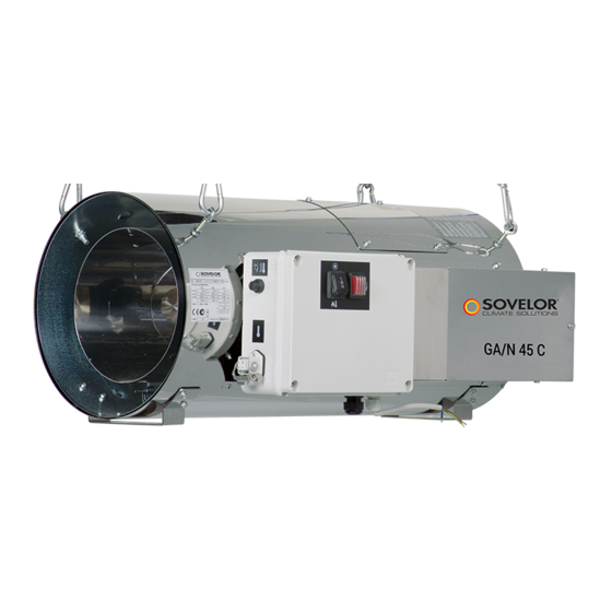
- Page 1 GA/N45C...
- Page 2 SCHEMA DI FUNZIONAMENTO - SCHÉMA DE FONCTIONNEMENT FUNKTIONSPLAN - OPERATING DIAGRAM ESQUEMA DE FUNCIONAMIENTO - СХЕМА РАБОТЫ 1 CAMERA DI COMBUSTIONE 5 ELETTRODO DI IONIZZAZIONE CHAMBRE DE COMBUSTION ELECTRODE D'IONISATION BRENNKAMMER IONISATIONSELEKTRODE COMBUSTION CHAMBER IONISATION ELECTRODE CAMARA DE COMBUSTION ELECTRODO DE IONIZACION КАМЕРА...
- Page 3 QUADRO COMANDI - TABLEAU DE COMMANDE BEDIENBLENDE - CONTROL BOARD TABLERO DE MANDOS - ЩИТ УПРАВЛЕНИЯ INTERRUPTEUR CHAUFFAGE ANZEIGE SICHERHEITSTHERMOSTATE OVERHEAT THERMOSTATS LAMP, SCHALTER HEIZUNG HEATING SWITCH TESTIGO TERMOSTATOS DE SEGURIDAD INTERRUPTOR DE LA CALEFACCIÓN ИНДИКАТОР ПРЕДОХРАНИТЕЛЬНЫХ ВЫКЛЮЧАТЕЛЬ НАГРЕВА ТЕРМОВЫКЛЮЧАТЕЛЕЙ INTERRUTORE VENTILATORE LAMPADA PRESSOSTATO GAS TÉMOIN PRESSOSTAT GAZ...
- Page 4 ETICHETTA IDENTIFICAZIONE PRODOTTO – PLAQUETTE IDENTIFICATION PRODUIT TYPENSCHILD - PRODUCT IDENTIFICATION PLATE ETIQUETA DE IDENTIFICACIÓN DEL PRODUCTO – ПАСПОРТНАЯ ТАБЛИЧКА ИЗДЕЛИЯ SERIAL NUMBER GEMETEN THERMISCH VERMOGEN COSTRUTTORE CONSTRUCTEUR NÚMERO DE SERIE MOC CIEPLNA ZMIERZONA HERSTELLER ПАСПОРТНЫЙ НОМЕР MANUFACTURER SERIENUMMER CONSUMO GAS MISURATO FABRICANTE NUMER SERYJNY CONSOMMATION GAZ MESURE...
- Page 5 IMPORTANT Avant toute utilisation du générateur, nous vous prions de lire attentivement toutes les instructions pour l'emploi mentionnées ciaprès et d'en suivre scrupuleusement les indications. Le constructeur n'est pas responsable des dommages aux personnes et/ou aux biens dus à une utilisation impropre de l'appareil. Ce livret d'utilisation et d'entretien est partie intégrante de l'appareil.
- Page 6 2. CONDITIONS DE FOURNITURE Le générateur d’air est livré emballé sur une palette en bois et il peut être facilement manutentionné à l’aide d’un chariot élévateur manuel ou automatique, ayant une charge utile de plus de 200 kg. Attention Ne jamais essayer de soulever manuellement le générateur : son poids excessif risque d'entraîner des lésions physiques importantes.
- Page 7 4. CONSEILS D'ORDRE GÉNÉRAL L'installation, le réglage et l'utilisation du générateur d'air chaud doivent être accomplis dans le respect de toutes les normes et des lois nationales et locales en vigueur en matière d’utilisation de la machine. Il est conseillé de s'assurer que : •...
- Page 8 5. INSTRUCTIONS D'INSTALLATION Attention Toutes les instructions fournies dans ce paragraphe ne doivent être exécutées que par un personnel qualifié. 4.1. INSTALLATION AU SOL OU AU PLANCHER Le générateur d’air chaud peut être installé sur une base de support qui doit être : •...
- Page 9 la température maximale de sortie, qui peut être calculée à partir du total de la température ambiante + ΔT @ 1,5 m (comme indiqué sur l'étiquette appliquée sur le générateur d'air chaud). 5.2. BRANCHEMENTS ÉLECTRIQUES 5.2.1 Raccordement au réseau d’alimentation électrique Attention La ligne d'alimentation électrique doit être équipée d'une mise à...
- Page 10 Attention Ne jamais essayer de mettre en marche ou d'arrêter le générateur en branchant le thermostat d'ambiance (ni aucun autre dispositif de contrôle) sur la ligne d'alimentation électrique. 5.2.3 Raccordement au système de commande climatique Le générateur d’air chaud est prévu pour être raccordé à un système de commande climatique à...
- Page 11 5.3 BRANCHEMENT À LA LIGNE D'ALIMENTATION DU COMBUSTIBLE Attention Les prescriptions d'installation, de réglage et d'utilisation visées par les réglementations régionales et/ou nationales concernant l'emploi du générateur d'air chaud doivent IMPÉRATIVEMENT toujours être respectées. Attention Avant de procéder à la mise en place, vérifier les conditions d’alimentation requises en fonction du type de gaz (gaz naturel ou GPL) et du pays d’installation.
- Page 12 Le générateur d’air chaud est doté d’une soupape de gaz contenant les éléments suivants : filtre à gaz, régulateur de pression, électrovanne de sécurité, électrovanne de fonctionnement, stabilisateur de pression, prises de pression. Il est recommandé à l’installateur de préparer la ligne d’alimentation comme suit : 8: générateus d’air chaud 9:flexible gaz basse pression 10: vanne d’arrêt...
- Page 13 Attention Le generateur d'air chaud est conçu pour une pression d’alimentation maximale de 60 mbars VÉRIFIER QUE LA PRESSION D’ALIMENTATION DU GAZ NE DÉPASSE JAMAIS 60 MBARS. Si la pression d’alimentation dépasse cette valeur, la membrane de sécurité de la soupape du gaz pourrait se gripper et entraîner le blocage de sécurité...
- Page 14 5.6. PREMIER DEMARRAGE Ce n'est qu’après avoir vérifié que le générateur d'air chaud est correctement configuré pour la catégorie de gaz d’alimentation, qu’il sera possible de procéder au premier démarrage. Tout d’abord, exécuter de nouveau les opérations suivantes: • Purger la canalisation d’alimentation du gaz ; Vérifier l’étanchéité...
- Page 15 4) Ouvrir la prise de pression (13) à la sortie de la soupape de gaz et raccorder le second manomètre pour afficher la pression du brûleur p 5) Brancher l’alimentation électrique et faire démarrer le générateur d’air chaud. 6) Agir sur le régulateur de pression de l’installation d’alimentation du gaz, de manière à ce que la valeur p affichée soit stable et corresponde à...
- Page 16 6. INSTRUCTIONS D'UTILISATION 6.1 MISE EN MARCHE Pour mettre le générateur en marche (Fig. 1): • S'assurer que l'interrupteur (A) est sur la position “0” ; • Alimenter l'appareil en agissant sur l'interrupteur général du coffret électrique d'alimentation. • Présélectionner le mode de post-ventilation (ventilation de refroidissement du générateur d’air chaud lors de l'extinction de la flamme), en plaçant le commutateur (B) en position (0) pour la post-ventilation temporisée (le ventilateur aussi s'arrête 90 s après l’extinction de la flamme) ou en position (I) pour la post-ventilation continue (le ventilateur continue de fonctionner) ;...
- Page 17 7. MAINTENANCE Attention Toutes les instructions fournies dans ce paragraphe ne doivent être exécutées que par un personnel qualifié. Pour assurer un fonctionnement régulier de l’appareil, il est nécessaire de procéder périodiquement aux opérations suivantes, en prenant soin d’exclure la ligne électrique d’alimentation du générateur. Attention Avant toute opération : •...
- Page 18 7.2 NETTOYAGE EXTERIEUR DE LA MACHINE Pour garantir un fonctionnement correct, nettoyer les éléments suivants : • Tuyaux, connecteurs et joints: nettoyer à l’aide d’un chiffon. • Carénage extérieur: nettoyer à l’aide d’un chiffon. • Entrée/Sortie de l’air: • Eliminer toute la saleté et les résidus accumulés •...
- Page 19 8. ANOMALIES DE FONCTIONNEMENT, CAUSES ET SOLUTIONS En cas de grave anomalie, l’équipement électronique entraînera le blocage de sécurité du générateur d’air chaud et le témoin (D) s’allumera en rouge fixe (signalisation de blocage). Attention Après un blocage de sécurité, il est nécessaire d'appuyer sur le bouton réarmement (8) pendant 3 secondes pour faire redémarrer le générateur.
- Page 20 ANOMALIE DE CAUSE SOLUTION FONCTIONNEMENT • Vérifier le fonctionnement et la position de l'interrupteur • L'appareil ne démarre pas: • Manque d'alimentation • Vérifier les caractéristiques du réseau électrique électrique le témoin est éteint • Vérifier les branchements électriques • Vérifier que le fusible est intact •...
- Page 21 ANOMALIE DE CAUSE SOLUTION FONCTIONNEMENT LANCER LA PROCEDURE D’AUTODIAGNOSTIC • L'appareil ne fonctionne pas : APPUYER SUR LE BOUTON (D) PENDANT 12 SECONDES, PUIS LE RELACHER : le témoin est allumé fixe LE TEMOIN DU BOUTON CLIGNOTE (2 A 7 CLIGNOTEMENTS) •...
- Page 22 IMPORTANT Before using the space heater, carefully read all of the instructions and follow them scrupulously. The manufacturer cannot be held responsible for damage to persons and/or property caused by improper use of the equipment. This instruction manual is an integral part of the equipment and must therefore be stored carefully and passed on with the unit in the event of a change of ownership.
- Page 23 2. CONDITIONS OF SUPPLY The space heater is delivered packed on a wood pallet and can easily be handled with a manual or automatic fork lift with capacity exceeding 200 kg. Warning Never try to lift the heater manually: doing so could cause serious physical injury. It contains: •...
- Page 24 4. GENERAL ADVICE The space heater must be installed, adjusted, and used in conformity to national and local laws and regulations for its operation. General guidelines: • Follow the instructions in this booklet very carefully; • Do not install the heater in places where there is a risk of fire or explosion; •...
- Page 25 5. INSTALLATION INSTRUCTIONS Warning All of the operations described in this section must be performed by professionally qualified personnel only. 5.1. INSTALLATION ON FLOOR OR CEILING The space heater can be installed on a support base, which must be: • stable and horizontal •...
- Page 26 The minimum proximity of objects, property, persons and/or animals to be kept in front of the air distribution area must be at least 1,5 m, having checked that they can support the maximum temperature, which can be found by adding the room temperature + ΔT @ 1.5 m (as shown on the identification label affixed to the space heater itself).
- Page 27 Warning Never attempt to switch the heater on or off by connecting the room thermostat (or other control devices) to the electrical power line. 5.2.3 Connection to climate control system The space heater has been set up for connection to a remote climate control system: therefore, the heating function (button A), the ventilation function (button B), the voltage warning lamp signal display (lamp E) and the reset button warning lamp (lamp D) can all be managed.
- Page 28 Warning Before installation, check that there are the required gas supply conditions according to the type of gas chosen (natural gas or LPG) and according to the country of installation. • For European countries: identify the conditions to be used in Table I (natural gas) or Table II (LPG). Supply Burner European...
- Page 29 8: space heater 9: low pressure flexible gas tubing 10: stopcock 11: Filter – Gas regulator 8: space heater 9: medium pressure flexible gas tubing 10: stopcock 11: Filter – Gas regulator Parts (9), (10) and (11) are available as accessories and are not supplied with the heater. Warning Only for the 45 kW model Before connecting the heater to the gas supply line, the gas connection fitting (supplied with the space heater)
- Page 30 5.4. PREPARATION OF THE GAS BURNER The space heater is set up in the factory by the manufacturer for one of the operating categories in Table I or Table II. An adhesive label applied to the gas valve casing will indicate this operating category and the supply pressure for which the burner has been prepared and tested: that is to say the type of diffuser ring (3) and the gas valve adjustment.
- Page 31 Warning The gas valve group is set for a maximum supply pressure of 60 mbar. If the supply pressure exceeds this value, the valve safety membrane may rupture and put the valve into a permanent safety block. Warning Before starting the heater in heating mode, check the direction of fan rotation: •...
- Page 32 5) Connect the power supply and start the space heater. 6) Using the gas supply system pressure regulator, adjust the p level reading until it corresponds to the required value and is stable. 7) Using the gas valve pressure regulator (14), adjust the p level reading until it corresponds to the required value and is stable.
- Page 33 6. OPERATING INSTRUCTIONS 6.1 START-UP To start the space heater (Fig. 1): • Make sure the switch (A) is set to “0”. • Switch on power to the heater by means of the isolation switch on the power switchboard. • Pre-select the post-ventilation mode (space heater cooling ventilation when the flame goes out) by setting the switch (B) to position (0) for timed post-ventilation (90 seconds after the flame goes out, the fan will also stop) or to position (I) for continuous post-ventilation (the fan continues to run).
- Page 34 7. MAINTENANCE Warning All of the operations described in this section must be performed by professionally qualified personnel only. The following procedures must be done at regular intervals to ensure efficient operation of the heater. Make sure you have detached the electrical power line from the heater before starting any work. Warning Before doing any maintenance: •...
- Page 35 7.2 CLEANING THE EXTERIOR OF THE HEATER To ensure efficient operation, clean the following parts: • Pipes, connectors and joints: • Clean with a cloth. • External body: • Clean with a cloth. • Air inlet/outlet: • Remove all dirt and debris •...
- Page 36 8. TROUBLESHOOTING In case of serious malfunction, the electronic equipment causes the heater to go into safety stop, and lamp (D) lights with a steady red light (stop light). Warning In case of a safety stop, you have to push the reset button (8) for 3 seconds to restart the heater. Warning NEVER do more than two restarts in a row: unburned fuel can accumulate in the combustion chamber and suddenly flare up at the next restart.
- Page 37 FAULT CAUSE REMEDY • Check functioning and position of switch • The heater does not start: • No power supply • Check the mains lamp is off • Check power connections • Check the fuse • Switch (A) in wrong position •...
- Page 38 FAULT CAUSE REMEDY LAUNCH THE SELF-DIAGNOSIS PROCEDURE • The heater does not work: PUSH BUTTON (D) FOR 12 SECONDS AND RELEASE: lamp is steady on THE BUTTON LAMP FLASHES WITH 2 TO 7 FLASHES • Check gas pressure at burner •...
- Page 39 REGOLAZIONE PRESSIONE GAS BRUCIATORE - PRESSION GAZ BRÛLEUR - DÜSENDRUCK GAS MANIFOLD PRESSURE - PRESIÓN GAS QUEMADOR - ДАВЛЕНИЕ ГАЗА ГОРЕЛКИ L-L 304.00-BM 108 / 116...
- Page 40 L-L 304.00-BM 109 / 116...
- Page 41 REGOLAZIONE PRESSIONE GAS BRUCIATORE - PRESSION GAZ BRÛLEUR - DÜSENDRUCK GAS MANIFOLD PRESSURE - PRESIÓN GAS QUEMADOR - ДАВЛЕНИЕ ГАЗА ГОРЕЛКИ L-L 304.00-BM 110 / 116...
- Page 42 SCHEMA ELETTRICO - SCHEMA ELECTRIQUE – SCHALTSCHEMA WIRING DIAGRAM - ESQUEMA ELÉCTRICO - ЭЛЕКТРОСХЕМА L-L 304.00-BM 112 / 116...
- Page 43 SCHEMA ELETTRICO - SCHEMA ELECTRIQUE – SCHALTSCHEMA WIRING DIAGRAM - ESQUEMA ELÉCTRICO - ЭЛЕКТРОСХЕМА CONDENSATORE PRESA TERMOSTATO AMBIENTE CONDENSATEUR PRISE THERMOSTAT D’AMBIACE KONDENSATOR RAUMTHERMOSTAT STECKDOSE CONDENSER ROOM THERMOSTAT PLUG CONDENSADOR ENCHUFE TERMOSTATO AMBIENTE КОНДЕНСАТОР РАЗЪЕМ ТЕРМОСТАТА ОКРУЖАЮЩЕЙ СРЕДЫ MOTORE VENTILATORE PULSANTE DI RIARMO MOTEUR VENTILATEUR BOUTON REARMEMENT...
- Page 44 CARATTERISTICHE TECNICHE - CARACTERISTIQUES TECHNIQUES GA/N 45 C TECHNISCHEN DATEN - TECHNICAL SPECIFICATIONS CARACTERÍSTICAS TÉCNICAS - ТЕХНИЧЕСКИЕ ХАРАКТЕРИСТИКИ Potenza termica nominale – Puissance thermique nominale Wärmeleistung bewertet – Nominal heating output [kW] Potencia termica nominal - Тепловая Номинальная мощность [kW] 45,64 Potenza termica misurata –...
- Page 45 GA/N 45C L-D610.00-BM 27 28...
- Page 46 GA/N 45C L-D610.00-BM Da N.° serie Von Masch. Nr. From S/N от з / п PL 01/18 De No. Serie 49000101 LEGENDA DESCRIZIONE DESCRIPTION BESCHREIBUNG DESCRIPTION ОПИСАНИЕ P30175 Griglia aspirazione Grille aspiration Ansauggitter Inlet grill решетка входная E10746 220 W - 230 V - 50 Hz Motore Moteur Motor...
- Page 47 GA/N 45C L-D610.00-BM Da N.° serie Von Masch. Nr. From S/N от з / п PL 01/18 De No. Serie 49000101 LEGENDA DESCRIZIONE DESCRIPTION BESCHREIBUNG DESCRIPTION ОПИСАНИЕ E20985 Dado per pressacavo Ecrou pour presse étoupe Mutter für Kabeldurchgang Cable fastener nut PG 36 Гайка...
- Page 48 Dantherm S.p.A. Dantherm S.p.A. Via Gardesana 11, -37010- 11, 37010 Pastrengo (VR), ITALY Dantherm Sp. z o.o. Dantherm Sp. z o.o. ul. Magazynowa 5A, 62-023 Dantherm SAS Dantherm SAS Dantherm LLC ul. Transportnaya 22/2, Dantherm China LTD Dantherm China LTD Dantherm SP S.A.