Table des Matières
Publicité
Les langues disponibles
Les langues disponibles
Liens rapides
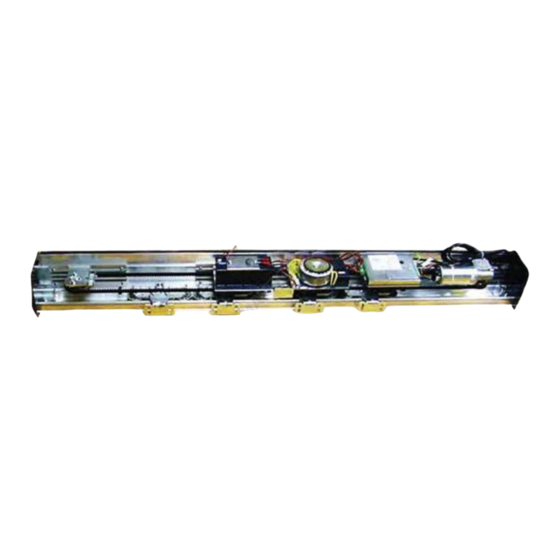
MODULO WING NK
SCOPO DEL MANUALE
Questo manuale è stato redatto dal costruttore ed è parte integrante del prodotto.
In esso sono contenute tutte le informazioni necessarie per:
• la corretta sensibilizzazione degli installatori alle problematiche della sicurezza;
• la corretta installazione del dispositivo;
• la conoscenza approfondita del suo funzionamento e dei suoi limiti;
• il corretto uso in condizioni di sicurezza;
La costante osservanza delle indicazioni fornite in questo manuale, garantisce la sicurezza dell'uomo, l'economia
di esercizio e una più lunga durata di funzionamento del prodotto.
Al fi ne di evitare manovre errate con il rischio di incidenti, è importante leggere attentamente questo manuale,
rispettando scrupolosamente le informazioni fornite.
Le istruzioni, i disegni, le fotografi e e la documentazione contenuti nel presente manuale sono di proprietà
APRIMATIC S.p.a. e non possono essere riprodotti in alcun modo, né integralmente, né parzialmente.
Il logo "APRIMATIC" è un marchio registrato di APRIMATIC S.p.a.
PURPOSE OF THE MANUAL
This manual was drawn up by the manufacturer and is an integral part of the product.
It contains all the necessary information:
• to draw the attention of the installers to safety related problems
• to install the device properly
• to understand how it works and its limits
• to use the device under safe conditions
Strict observance of the instructions in this manual guarantees safe conditions as well as effi cient operation
and a long life for the product.
To prevent operations that may result in accidents, read this manual and strictly obey
the instructions provided.
Instructions, drawings, photos and literature contained herein are the exclusive property of
the manufacturer and may not be reproduced by any means.
The "Aprimatic" logo is a trademark registered by Aprimatic S.p.A.
BUT DU MANUEL
Ce manuel a été rédigé par le constructeur et fait partie intégrante du produit.
Il contient toutes les informations nécessaires pour :
• sensibiliser les installateurs aux problèmes liés à la sécurité ;
• installer le dispositif de manière correcte ;
• connaître le fonctionnement et les limites du dispositif ;
• utiliser correctement le dispositif dans des conditions de sécurité optimales ;
Le respect des indications fournies dans ce manuel garantit la sécurité personnelle, une économie de
fonctionnement et une longue durée de vie du produit.
Afi n d'éviter des opérations incorrectes et de ne pas risquer des accidents sérieux, lire attentivement ce manuel
et respecter scrupuleusement les informations fournies.
Les instructions, les dessins, les photos et la documentation contenus dans ce manuel sont la propriété
d'APRIMATIC S.p.A. et ne peuvent être reproduits sous aucune forme, ni intégralement, ni partiellement.
Le logo « Aprimatic » est une marque déposée par Aprimatic S.p.A.
ZWECK DES HANDBUCHS
Dieses Handbuch wurde vom Hersteller verfasst und ist ein ergänzender Bestandteil des Produkts.
Es enthält alle nötigen Informationen für:
• die Sensibilisierung der Monteure für Fragen der Sicherheit;
• die vorschriftsmäßige Installation der Vorrichtung;
• die umfassende Kenntnis ihrer Funktionsweise und ihrer Grenzen;
• die vorschriftsmäßige und sichere Benutzung.
Die Beachtung der in diesem Handbuch enthaltenen Anweisungen gewährleistet die Sicherheit der Personen,
den wirtschaftlichen Betrieb und eine lange Lebensdauer des Produkts.
Zur Vermeidung von Fehlbedienung und somit Unfallgefahr dieses Handbuch aufmerksam durchlesen und
die Anweisungen genau befolgen.
Die Anleitungen, Zeichnungen, Fotos und Dokumentationen in diesem Handbuch sind Eigentum von APRIMATIC
S.p.A. und dürfen in keiner Weise ganz oder teilweise reproduziert werden.
Das Logo „Aprimatic" ist ein eingetragenes Warenzeichen der Aprimatic S. p. A.
OBJETO DEL MANUAL
Este manual ha sido redactado por el constructor y forma parte integrante del producto.
El mismo contiene todas las informaciones necesarias para:
• la correcta sensibilización de los instaladores hacia los problemas de la seguridad
• la correcta instalación del dispositivo
• el conocimiento en profundidad de su funcionamiento y de sus límites
• el correcto uso en condiciones de seguridad
La constante observación de las indicaciones suministradas en este manual, garantiza la seguridad del hombre, la
economía del ejercicio y una mayor duración de funcionamiento del producto.
Con el fi n de evitar maniobras equivocadas con riesgo de accidente, es importante leer atentamente este manual,
respetando escrupulosamente las informaciones suministradas.
Las instrucciones, los dibujos, las fotografías y la documentación que contiene este manual son propiedad de
APRIMATIC S.p.a. y no pueden ser reproducidas en ninguna manera, ni integral ni parcialmente.
El logotipo "Aprimatic" es una marca registrada de Aprimatic S. p. A.
WING NK MODULE
MODULE WING NK
MODULO WING NK
MÓDULO WING NK
Istruzioni per l'istallazione meccanica
Mechanical installation instructions
Instructions pour le montage mécanique
Anleitung für die mechanische Installation
Instrucciones para la instalación mecánica
Reservadas para el instalador
Riservate all'installatore
Reserved for installers
Réservées à l'installateur
Nur für Installateure
Publicité
Chapitres
Table des Matières

Manuels Connexes pour Aprimatic WING NK


Sommaire des Matières pour Aprimatic WING NK
- Page 1 Le istruzioni, i disegni, le fotografi e e la documentazione contenuti nel presente manuale sono di proprietà APRIMATIC S.p.a. e non possono essere riprodotti in alcun modo, né integralmente, né parzialmente. Il logo “APRIMATIC” è un marchio registrato di APRIMATIC S.p.a.
-
Page 2: Table Des Matières
GLOSSARIO Le presenti istruzioni riguardano esclusivamente Il manuale istruzioni utilizza diffusamente termini tecnici l’installazione meccanica del MODULO WING NK e della adeguati ai professionisti dell’area tecnica ai quali è destinato. puleggia folle. Il seguente glossario precisa il significato specifico con cui... -
Page 3: Avvertenze Generali Di Sicurezza
Installazione, collegamenti elettrici e regolazioni devono preassemblati su un unico supporto. essere effettuati nell’osservanza della BUONA TECNICA e in Il Modulo WING NK è stato progettato e prodotto ottemperanza alle norme vigenti nel paese di installazione. esclusivamente per l’impiego su porte automatiche con una Il costruttore della motorizzazione non è... -
Page 4: Dati Tecnici
Cinghia di trasmissione • KIT ferramenta* In fi g.1 e tab.2 il MODULO WING NK con la L’utilizzo è illustrato nel libretto istruzioni Sistema PULEGGIA folle e i componenti non assemblati inclusi trave NK con Ante scorrevoli fornito in allegato. -
Page 5: Installazione Modulo E Puleggia
Per la realizzazione dell’installazione elettrica e il movimentazioni per evitare rischi d’urto e di caduta. corretto utilizzo dell’automazione forniamo in allegato il libretto istruzioni WING NK CONTROL SYSTEM. 1 Inserire il Modulo nell’apposita sede e agganciarlo alla Trave NK eseguendo le semplici manovre illustrate in fi... -
Page 6: Posizionamento Modulo E Puleggia
POSIZIONAMENTO MODULO E PULEGGIA La tab.3 fornisce le quote per il corretto posizionamento del Modulo e della Puleggia sulla traversa in base al tipo di tab.3 A ; B installazione realizzata (fig.5a o 5b). (mm) (mm) 1800 2000 2400 2500 2800 3000 3200... -
Page 7: Symbols Used
These instructions only concern the mechanical The instruction manual uses suitable technical terms for installation of the WING NK MODULE and the idle pulley. professionals working in the technical sector for which it is intended. The following glossary explains the specific meaning... -
Page 8: General Safety Recommendations
Directive 92/57/EEC concerning the minimum rules and regulations on health and safety at work to be observed when The WING NK Module has been designed and manufactured working on temporary or mobile sites”). exclusively for use on automatic doors with one or two... -
Page 9: Technical Specifications
Use of the hardware kit is illustrated in the NK beam with sliding wing system Instruction Manual enclosed. Fig. 1 and Tab. 2 illustrate the WING NK MODULE with the idle PULLEY and the non-assembled components included in the pack. -
Page 10: Installing The Module And Pulley
6 Secure the Module and Pulley by tightening down all the loosen the adjustment screw to set the maximum X distance screws on the beam profi le. possible; 7 Make the connections, referring to the WING NK Control when finished, tighten the 2 securing screws again. System Manual enclosed. INSERT... -
Page 11: Positioning The Module And Pulley
POSITIONING THE MODULE AND PULLEY Table 3 indicates the measurements for the correct positioning of the Module and Pulley on the beam for each type of tab.3 A ; B installation (Fig. 5a or Fig. 5b). (mm) (mm) 1800 2000 2400 2500 2800... -
Page 12: Symboles Utilisés
Informations Les présentes instructions concernent exclusivement symbole précède INFORMATIONS le montage mécanique du MODULE WING NK et de la considérées comme étant particulièrement utiles. poulie folle. GLOSSAIRE Consulter les instructions fournies en annexe: Le manuel d’instructions utilise des termes techniques bien •... -
Page 13: Normes Générales De Sécurité
»). Le Module WING NK est conçu et produit exclusivement pour Le montage, les connexions électriques et les réglages doivent une utilisation sur des portes automatiques à un ou deux être réalisés dans les RÈGLES DE L’ART, conformément aux... -
Page 14: Caractéristiques Techniques
L’utilisation du Kit ferrure est illustré dans le manuel d’instructions Système poutre NK La fi g. 1 et le tab. 2 montrent le MODULE WING NK avec vantaux coulissants fourni ci-joint. avec la POULIE folle ainsi que les composants non assemblés compris dans l’emballage de vente. -
Page 15: Montage Du Module Et De La Poulie
WING NK CONTROL SYSTEM. 1 Mettre le module dans le logement prévu à cet effet et le fi xer à la poutre NK en effectuant les simples manoeuvres indiquées aux fi... -
Page 16: Positionnement Du Module Et De La Poulie
POSITIONNEMENT DU MODULE ET DE LA POULIE Le tab. 3 fournit les cotes nécessaires au positionnement tab.3 A ; B du module et de la poulie sur la traverse, selon le type (mm) (mm) d’installation réalisé (fig. 5a ou 5b). 1800 2000 2400... -
Page 17: Verwendete Symbole
• TRÄGERSYSTEM NK (für die Vorbereitung des Trägers); verwendet, die für Anwender auf dem technischen Gebiet • WING NK CONTROL SYSTEM (für die Anschlüsse). gedacht sind, für das sie bestimmt ist. Im folgenden Glossar wird die genaue Bedeutung einiger im Text verwendeter Achtung technischer Begriffe erläutert:... -
Page 18: Allgemeine Sicherheitshinweise
Hauptkomponenten der Automatik bereits auf einer einzigen Halterung vormontiert sind. Installation, Elektroanschlüsse und Einstellungen müssen nach den ALLGEMEIN ANERKANNTEN REGELN DER Modulo WING NK wurde ausschließlich für die Verwendung TECHNIK und unter Beachtung der im Installationsland bei ein- oder zweiflügeligen Automatik-Schiebetüren mit geltenden Bestimmungen durchgeführt werden. -
Page 19: Technische Daten
• KIT mit Kleinteilen* Die Verwendung wird in der beiliegenden Anleitung Aus Abb. 1 und Tab. 2 sind das MODUL WING NK Trägersystem NK mit Schiebetürfl ügeln erläutert. mit UMLENKSCHEIBE und die in der Verkaufpackung enthaltenen und nicht montierten Bestandteile ersichtlich. -
Page 20: Montage Des Moduls Und Der Riemenscheibe
Anziehen der Schrauben auf dem Profil des Trägers Die Einstellschraube lockern, bis sich der max. mögliche Abstand festmachen. X ergibt. 7 Die Anschlüsse gemäß beiliegender Anleitung WING NK Schließlich die 2 Sicherungsschrauben wieder anziehen. Control System vornehmen. Modul Modul... -
Page 21: Anordnung Des Moduls Und Der Riemenscheibe
ANORDNUNG DES MODULS UND DER RIEMENSCHEIBE Die Tab. 3 zeigt die Maße für die richtige Anordnung des tab.3 A ; B Moduls und der Riemenscheibe auf dem Träger je nach (mm) (mm) gewünschter Anwendung (Abb. 5a bzw. 5b). 1800 2000 2400 2500 2800... -
Page 22: Símbolos Utilizados
INFORMACIONES Las presentes instrucciones se refieren exclusivamente consideradas de especial utilidad. a la instalación mecánica del MODULO WING NK y de la polea loca. GLOSARIO Consulte las instrucciones adjuntas: En el manual de instrucciones se emplean vocablos técnicos •... -
Page 23: Advertencias Generales De Seguridad
único soporte. temporales o móviles”). El Módulo WING NK ha sido proyectado y producido Instalación, conexiones eléctricas y regulación deben ser exclusivamente para puertas automáticas con una o dos efectuadas respetando la BUENA TÉCNICA y cumpliendo las... -
Page 24: Datos Técnicos
Sistema traviesa NK con Hojas correderas En la fi g.1 y en la tab.2 se muestran el MODULO que se adjunta al producto. WING NK con la POLEA loca y los componentes no ensamblados incluidos en el kit. fi g.1 Componentes del MÓDULO... -
Page 25: Instalación Del Módulo Y De La Polea
7 Realizar las conexiones como se especifi ca en el manual para finalizar, apretar de nuevo los 2 tornillos de bloqueo. WING NK Control System que se adjunta al equipo. INTRODUCIR ENGANCHAR introducir los 7 tornillos de fijación el Módulo... - Page 26 POSICIONAMIENTO DEL MÓDULO Y DE LA POLEA La tab.3 proporciona las medidas para el correcto tab.3 A ; B posicionamiento del Módulo y de la Polea en el travesaño en (mm) (mm) función del tipo de instalación realizada (fig.5a o 5b). 1800 2000 2400...