
Manuels Connexes pour Wilo Para


Sommaire des Matières pour Wilo Para
- Page 1 Wilo-Para de Einbau- und Betriebsanleitung en Installation and operating instructions Notice de montage et de mise en service APPLIES TO EUROPEAN DIRECTIVE FOR ENERGY RELATED PRODUCTS...
- Page 2 Fig. 1: Para.../SC Para.../iPWM...
- Page 3 Fig. 2: Fig. 4: Fig. 5a: Fig. 3: Fig. 5b: PE N...
- Page 4 Fig. 5c: Fig. 5f: Fig. 5d: Fig. 6: Fig. 5e:...
- Page 5 Sach- und Personenschäden ver- Sicherheitshinweisen wendet und unterschiedlich dargestellt: • Sicherheitshinweise für Personenschäden beginnen mit einem Signalwort und haben ein entsprechendes Symbol vorangestellt. • Sicherheitshinweise für Sachschäden beginnen mit einem Signalwort und werden ohne Symbol dargestellt. Einbau- und Betriebsanleitung Wilo-Para...
- Page 6 Das Personal muss die folgenden Qualifikationen haben: • Elektrische Arbeiten müssen von einer Elektro- fachkraft (nach EN 50110-1) durchgeführt werden. • Montage/Demontage muss von einer Fachkraft durchgeführt werden, die im Umgang mit den not- wendigen Werkzeugen und erforderlichen Befes- tigungsmaterialien ausgebildet ist. Wilo SE 08/2017...
- Page 7 Erfahrung und Wissen genutzt werden, wenn sie beauf- sichtig oder bezüglich des sicheren Gebrauchs des Geräts unterwiesen wurden und sie die daraus resultierenden Gefahren verstehen. Kinder dürfen nicht mit dem Gerät spielen. Reinigung und Benutzerwartung dürfen nicht von Kindern ohne Beaufsichtigung durchgeführt werden. Einbau- und Betriebsanleitung Wilo-Para...
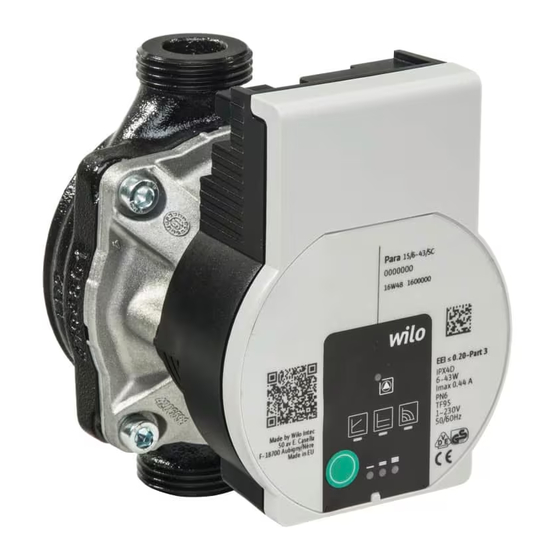
- Page 8 3 Produktbeschreibung und Funktion Übersicht Wilo-Para (Fig. 1) 1 Pumpengehäuse mit Verschraubungsanschlüssen 2 Nassläufermotor 3 Kondensatablauföffnungen (4x am Umfang) 4 Gehäuseschrauben 5 Regelmodul 6 Typenschild 7 Bedientaste zur Einstellung der Pumpe 8 Betriebs-/Störmelde LED 9 Anzeige der ausgewählten Regelungsart 10 Anzeige der ausgewählten Kennlinie (I, II, III) 11 PWM-Signalkabelanschluss oder LIN Signal (bei Para...-/PWM)
- Page 9 • LED leuchtet/blinkt bei Störung • Anzeige der gewählten Regelungsart Δp-v, Δp-c und Konstant-Drehzahl • Anzeige der gewählten Kennlinie (I, II, III) innerhalb der Regelungsart • Anzeigekombinationen der LEDs während der Entlüftungsfunktion, manuellem Neustart und Tastensperre Einbau- und Betriebsanleitung Wilo-Para...
- Page 10 Rohrleitungen oder allen (I, II, III) Anwendungen ohne veränderliche Rohrnetzkennlinie (z. B. Speicherladepumpen), sowie Einrohr-Heizungs- systeme mit Heizkörpern. Die Regelung hält die eingestellte Förderhöhe unabhängig vom geförderten Volumenstrom kontant. Drei vordefinierte Kennlinien (I, II, III) zur Auswahl. Q/m³/ h Wilo SE 08/2017...
- Page 11 < 5: Pumpe läuft bei maximaler Drehzahl 5-85: Die Drehzahl der Pumpe sinkt linear von n nach n 85-93: Pumpe läuft bei minimaler Drehzahl (Betrieb) 85-88: Pumpe läuft bei minimaler Drehzahl (Anlauf) 93-100: Pumpe stoppt (Bereitschaft) Einbau- und Betriebsanleitung Wilo-Para...
- Page 12 (8 Sekunden) der Bedientaste aktiviert und verriegelt die Einstellungen an der Pumpe. Sie schützt vor ungewollter oder unberechtigter Verstellung der Pumpe. 4 Bestimmungsgemäße Verwendung Hocheffizienz-Umwälzpumpen der Baureihe Wilo-Para dienen ausschließlich zum Umwälzen von Medien in Warmwasser-Heizungsanlagen und ähnlichen Systemen mit ständig wechselnden Förderströmen.
- Page 13 • Niemals mit Phasenanschnittsteuerung betreiben. 5 Transport und Lagerung Lieferumfang • Hocheffizienz-Umwälzpumpe • Einbau- und Betriebsanleitung Zubehör Zubehör muss gesondert bestellt werden, detaillierte Auflistung und Beschreibung, siehe Katalog. Folgendes Zubehör ist erhältlich: • Netzanschlusskabel • iPWM-Signalkabel Einbau- und Betriebsanleitung Wilo-Para...
- Page 14 WARNUNG! Verbrühungsgefahr durch heiße Medien! Heiße Fördermedien können zu Verbrühungen führen. Vor dem Einbau oder Ausbau der Pumpe oder dem Lösen der Gehäuseschrauben (4) Folgendes beachten: • Heizungssystem vollständig abkühlen lassen. • Absperrarmaturen schließen oder Heizungssystem entleeren. Wilo SE 08/2017...
- Page 15 Motorkopf drehen Motorkopf (2+5) vor Einbau und Anschließen der Pumpe drehen. • Gegebenenfalls Wärmedämmschale abnehmen. WARNUNG! Lebensgefahr durch Magnetfeld! Lebensgefahr für Personen mit medizinischen Implan- taten durch in der Pumpe verbauten Permanentmag- neten. • Rotor niemals herausnehmen. Einbau- und Betriebsanleitung Wilo-Para...
- Page 16 • Pumpe mit einem Maulschlüssel gegen verdrehen sichern und mit den Rohrleitungen dicht verschrau- ben. • Gegebenenfalls Wärmedämmschale wieder anbringen. VORSICHT! Mangelnde Wärmeabfuhr und Kondenswasser können Regelmodul und Nassläufermotor beschädigen. • Nassläufermotor (2) nicht wärmedämmen. • Alle Kondensatablauföffnungen (3) frei lassen. Wilo SE 08/2017...
- Page 17 • Stromart und Spannung müssen mit den Angaben auf dem Typenschild (6) übereinstimmen. • Maximale Vorsicherung: 10 A, träge. • Pumpe ausschließlich mit sinusförmiger Wechsel- spannung betreiben. • Schalthäufigkeit berücksichtigen: - Ein-/Ausschaltungen über Netzspannung ≤ 100/24 h. Einbau- und Betriebsanleitung Wilo-Para...
- Page 18 Netzanschlusskabel montieren (Fig. 3): Netzkabel 1. Standard: 3-adriges umspritztes Kabel mit Messing Aderendhülsen 2. Optional: Netzkabel mit 3-poligem Anschlussstecker 3. Optional: Wilo-Connectorkabel (Fig. 3, Pos. b) • Kabelbelegung: 1 gelb/grün: PE ( 2 blau: N 3 braun: L • Arretierungsknopf des 3-poligen Pumpensteckers herunterdrücken und den Stecker am Steckeran-...
- Page 19 Wilo-Connector demontieren • Anschlussleitung von der Spannungsversorgung trennen. • Wilo-Connector mit passendem Schraubendreher demontieren (Fig. 6). Anschluss an ein Die Pumpe kann im Austauschfall direkt an ein vor- vorhandenes Gerät handenes Pumpenkabel mit 3-poligem Stecker (z.B. Molex) angeschlossen werden (Fig. 3, Pos. a).
- Page 20 Kennlinien erfolgt im Uhrzeigersinn. • Bedientaste kurz (ca. 1 Sekunde) drücken LEDs zeigen die jeweils eingestellte Regelungsart und Kennlinie an. Die Darstellung der möglichen Einstellungen im Folgen- den, ausgehend von der Werkseinstellung (Konstant-Drehzahl / Kennlinie III): Wilo SE 08/2017...
- Page 21 Kennlinie Konstant-Drehzahl Konstant-Drehzahl Differenzdruck variabel Δp-v Differenzdruck variabel Δp-v Differenzdruck variabel Δp-v Differenzdruck konstant Δp-c Differenzdruck konstant Δp-c Differenzdruck konstant Δp-c Konstant-Drehzahl • Mit dem 9. Tastendruck ist die Werkseinstellung (Konstant-Drehzahl / Kennlinie III) wieder erreicht. Einbau- und Betriebsanleitung Wilo-Para...
- Page 22 Pumpe stillsetzen Im Falle von Beschädigungen an der Anschlussleitung oder anderen elektrischen Komponenten Pumpe umgehend stillsetzen. • Pumpe von der Spannungsversorgung trennen. • Wilo-Kundendienst oder Fachhandwerker kontaktieren. 9 Wartung Reinigung • Pumpe regelmäßig vorsichtig mit trockenem Staubtuch von Verschmutzungen befreien.
- Page 23 Kavitation durch Systemdruck innerhalb des Geräusche unzureichenden zulässigen Bereichs erhöhen Vorlaufdruck Förderhöheneinstellung überprüfen und ggf. niedrigere Höhe einstellen Gebäude wird Wärmeleistung der Sollwert erhöhen nicht warm Heizflächen zu gering Regelungsart auf Δp-c statt auf Δp-v stellen Einbau- und Betriebsanleitung Wilo-Para...
- Page 24 Netzspannung Netzspannung, Trockenlauf Luft in der Pumpe Wassermenge/ blinkt -druck und Überlast Schwergängiger Motor rot/grün Umgebungs- Pumpe wird außerhalb bedingungen der Spezifikation überprüfen betrieben (z.B. hohe Modultemperatur). Die Drehzahl ist niedriger als im Normalbetrieb. Wilo SE 08/2017...
- Page 25 Die LEDs blinken nacheinander im Uhrzeigersinn. • Zum Abbrechen die Bedientaste 5 Sekundendrücken. HINWEIS Nach erfolgtem Neustart zeigt die LED-Anzeige die zuvor eingestellten Werte der Pumpe. Lässt sich eine Störung nicht beheben, Fachhandwer- ker oder Wilo-Kundendienst kontaktieren. Einbau- und Betriebsanleitung Wilo-Para...
- Page 26 Sammelstellen abgeben. • Örtlich geltende Vorschriften beachten! Informationen zur ordnungsgemäßen Entsorgung bei der örtlichen Gemeinde, der nächsten Abfallentsor- gungsstelle oder bei dem Händler erfragen, bei dem das Produkt gekauft wurde. Weitere Informationen zum Recycling unter www.wilo-recycling.com Wilo SE 08/2017...
- Page 27 • Safety instructions relating to personal injury start with a signal word and are preceded by a corre- sponding symbol. Installation and operating instructions Wilo-Para...
- Page 28 • Be instructed about locally applicable regulations governing accident prevention. • Have read and understood the installation and oper- ating instructions. Personnel must be qualified as follows: • Electrical work must be carried out by a qualified electrician (in accordance with EN 50110-1). Wilo SE 08/2017...
- Page 29 Children are not allowed to play with the device. Cleaning and user maintenance is not allowed to be carried out by children without supervision. Installation and operating instructions Wilo-Para...
- Page 30 3 Product description and function Overview Wilo-Para (Fig. 1) 1 Pump housing with screwed connections 2 Glandless motor 3 Condensate drain openings (4x around circumference) 4 Housing screws 5 Control module 6 Rating plate 7 Operating button for pump adjustment...
- Page 31 • Display of selected control mode Δp-v, Δp-c and con- stant speed • Display of selected pump curve (I, II, III) within the control mode • LED indicator combinations during pump venting function, manual restart and key lock Installation and operating instructions Wilo-Para...
- Page 32 (e.g. storage charge pumps) or single-pipe heating systems with radiators. The control keeps the set delivery head constant irre- spective of the pumped volume flow. There are three pre-defined pump curves (I, II, III) to choose from. Q/m³/ h Wilo SE 08/2017...
- Page 33 < 5: Pump runs at maximum speed 5-85: The speed of the pump decreases linearly from to n 85-93: Pump runs at minimum speed (operation) 85-88: Pump runs at minimum speed (starting) 93-100: Pump stops (standby) Installation and operating instructions Wilo-Para...
- Page 34 It protects against undesired or unau- thorised adjustment of the pump. 4 Intended use High-efficiency circulators in the Wilo-Para series are exclusively intended for circulating fluids in hot-water heating systems and similar systems with constantly changing volume flows.
- Page 35 Accessories Accessories must be ordered separately. For a detailed list and description, consult the catalogue. The following accessories are available: • Mains connection cable • iPWM signal cable • Thermal insulation shell • Cooling shell Installation and operating instructions Wilo-Para...
- Page 36 Hot fluids can cause scalding. Before installing or removing the pump, or loosening the housing screws (4), note the following: • Allow the heating system to cool down completely. • Close shut-off devices or drain the heating system. Wilo SE 08/2017...
- Page 37 • If necessary, remove the thermal insulation shell. WARNING! Risk of fatal injury from magnetic field! Risk of fatal injury for people with medical implants due to permanent magnets installed in the pump. • Never remove the rotor. Installation and operating instructions Wilo-Para...
- Page 38 • Re-mount the thermal insulation shell if required. CAUTION! Insufficient heat dissipation and condensation water may damage the control module and the glandless motor. • Do not thermally insulate the glandless motor (2). • Ensure all condensate drain openings (3) are kept free. Wilo SE 08/2017...
- Page 39 • Only operate the pump with sinusoidal AC voltage. • Note the switching frequency: - On/off switching operations via mains voltage ≤ 100/24 h. - ≤ 20/h for a switching frequency of 1 min. between switching on/off via mains voltage. Installation and operating instructions Wilo-Para...
- Page 40 Installing the mains connection cable (Fig. 3): connection 1. Standard: 3-core coated cable with brass ferrules 2. Optional: Mains cable with 3-pin connection plug 3. Optional: Wilo-Connector cable (Fig. 3, item b) • Cable assignment: 1 yellow/green: PE ( 2 blue: N 3 brown: L •...
- Page 41 • Remove the Wilo-Connector using a suitable screw- driver (Fig. 6). Connection to an The pump can be directly connected to an existing pump existing device cable with a 3-pin plug (e.g. Molex) when being replaced (Fig. 3, item a).
- Page 42 • Press the operating button briefly (approx. 1 second). LEDs display the set control mode and pump curve. The following shows the various possible settings, beginning with the factory setting (constant speed / pump curve III): Wilo SE 08/2017...
- Page 43 Δp-v Constant differential pressure Δp-c Constant differential pressure Δp-c Constant differential pressure Δp-c Constant speed • Pressing the button for the 9th time returns to the factory setting (constant speed / pump curve III). Installation and operating instructions Wilo-Para...
- Page 44 • Disconnect the pump from the power supply. • Contact Wilo customer service or a specialist technician. 9 Maintenance Cleaning • Carefully remove dirt from the pump on a regular basis using a dry duster.
- Page 45 Check the delivery head and set it to a lower head if necessary Building does Thermal output of Increase setpoint not warm up the heating surfaces Set control mode to Δp-c instead of is too low Δp-v Installation and operating instructions Wilo-Para...
- Page 46 Air in the pump Check mains Flashes voltage, flow rate/ Overload Sluggish motor, pump red/ pressure and is operated outside of green ambient conditions its specifications (e.g. high module temperature). The speed is lower than during normal operation. Wilo SE 08/2017...
- Page 47 • To cancel, press and hold the operating button for 5 seconds. NOTICE After the restart, the LED display shows the previously set values of the pump. If the fault cannot be remedied, contact a specialist technician or Wilo customer service. Installation and operating instructions Wilo-Para...
- Page 48 • Observe the locally applicable regulations! Please consult your local municipality, the nearest waste disposal site, or the dealer who sold the product to you for information on proper disposal. Further recycling information at www.wilo-recycling.com Wilo SE 08/2017...
- Page 49 Signalisation de Dans cette notice de montage et de mise en service, des consignes de sécurité relatives aux dommages matériels consignes de et corporels sont signalées de différentes manières : sécurité Notice de montage et de mise en service Wilo-Para...
- Page 50 Mise en garde contre les champs magnétiques Avis Qualification du Le personnel doit : personnel • Connaître les dispositions locales en vigueur en matière de prévention des accidents. • Avoir lu et compris la notice de montage et de mise en service. Wilo SE 08/2017...
- Page 51 • Le client doit assurer la protection contre les contacts avec des composants brûlants et des risques électriques. • Faire remplacer les joints et les conduites de raccor- dement présentant des défauts. Notice de montage et de mise en service Wilo-Para...
- Page 52 Les opérations de nettoyage et d'entretien ne doivent pas être réalisées par des enfants sans surveillance. 3 Description du produit et fonctionnement Aperçu Wilo-Para (Fig. 1) 1 Corps de pompe avec raccords filetés 2 Moteur à rotor noyé 3 Circuits d'évacuation des condensats (4x sur la circonférence)
- Page 53 0,5 bar/1,0 bar (50 kPa/100 kPa) à +95 °C/+110 °C Témoins lumineux (LED) • Notification • La LED verte allumée indique un fonctionnement normal • La LED s'allume/clignote en cas de défauts Notice de montage et de mise en service Wilo-Para...
- Page 54 • Verrouiller/déverrouiller les touches (appuyer pendant 8 secondes) Modes de régulation et fonctions Pression Conseillé pour les systèmes de chauffage bitube à radia- différentielle teurs afin de réduire le bruit d'écoulement sur les robi- variable Δp-v nets thermostatiques. (I, II, III) Wilo SE 08/2017...
- Page 55 La pompe fonctionne de manière dans trois vitesses fixes prescrites (I, II, III). AVIS Réglage d'usine : Vitesse de rotation constante, courbe caractéristique III Q/m³/ h Notice de montage et de mise en service Wilo-Para...
- Page 56 PWM. Comportement en cas de rupture de câble : Si le câble de signal est séparé de la pompe, p. ex. par une 7 12 15 95 100 rupture de câble, la pompe s'arrête. Wilo SE 08/2017...
- Page 57 4 Applications Les circulateur à haut rendement de la gamme Wilo-Para servent uniquement à faire circuler des fluides dans des installations de chauffage à eau chaude et des systèmes analogues présentant des débits toujours changeants.
- Page 58 • Ne jamais faire effectuer des travaux non autorisés. • Ne jamais utiliser la pompe hors des limites d'utilisa- tion indiquées. • Ne jamais effectuer de modifications arbitraires. • Utiliser exclusivement les accessoires autorisés. • Ne jamais utiliser la pompe avec une commande par coupe. Wilo SE 08/2017...
- Page 59 • Ne toucher que le module de régulation (5) lors du fonctionnement. • Laisser refroidir la pompe avant d'effectuer un travail quelconque. Notice de montage et de mise en service Wilo-Para...
- Page 60 Les fuites d'eau peuvent endommager le module de régulation. • Orienter la vanne d'arrêt supérieure de telle sorte que des fuites d'eau ne puissent pas goutter sur le module de régulation (5). • Orienter latéralement la vanne d'arrêt supérieure. Wilo SE 08/2017...
- Page 61 • Faire tourner la tête du moteur (2+5) précautionneusement. • Respecter la position de montage autorisée (Fig. 2) et la flèche de direction sur le corps de pompe (1). • Visser les 4 vis du corps (4). Notice de montage et de mise en service Wilo-Para...
- Page 62 Une évacuation insuffisante de la chaleur et de l'eau de condensation peut endommager le module de régulation et le moteur à rotor noyé. • Ne pas isoler le moteur à rotor noyé (2) contre la cha- leur. • N'obstruer aucun circuit d'évacuation des condensats (3). Wilo SE 08/2017...
- Page 63 • Le type de courant et la tension doivent coïncider avec les indications portées sur la plaque signalétique (6). • Calibre de fusible maximum : 10 A, inerte. • Ne faire fonctionner la pompe que sur une tension alternative sinusoïdale. Notice de montage et de mise en service Wilo-Para...
- Page 64 électrique 2. En option : câble électrique avec fiche de raccorde- ment 3 pôles 3. En option : câble Wilo-Connector (Fig. 3, pos. b) • Affectation des câbles : 1 jaune/vert : PE ( 2 bleu : N 3 marron : L •...
- Page 65 (1000 Hz nominal) - Amplitude du signal : min. 3,6 V à 3 mA jusqu'à 24 V pour 7,5 mA, absorbée par l'interface de la pompe. - Polarité du signal : oui Notice de montage et de mise en service Wilo-Para...
- Page 66 Les rangées de LED supérieures et inférieures cligno- tent en alternance à intervalle d'une seconde. • Pour annuler, appuyer pendant 3 secondes sur la touche de commande. AVIS Après la purge, l'affichage LED affiche les valeurs préalablement réglées de la pompe. Wilo SE 08/2017...
- Page 67 Affichage LED Mode de régulation Courbe caractéristique Vitesse de rotation constante Vitesse de rotation constante Pression différentielle variable Δp-v Pression différentielle variable Δp-v Pression différentielle variable Δp-v Pression différentielle constante Δp-c Notice de montage et de mise en service Wilo-Para...
- Page 68 être modifiés. • La désactivation du verrouillage des touches s'effec- tue de la même façon que l'activation. AVIS Tous les réglages et affichages sont conservés en cas de coupure de l'alimentation électrique. Wilo SE 08/2017...
- Page 69 9 Entretien Nettoyage • Nettoyer régulièrement avec un chiffon sec les encrassements qui se déposent sur la pompe. • Ne jamais utiliser de liquides ou de produits de net- toyage agressifs. Notice de montage et de mise en service Wilo-Para...
- Page 70 évent. à hauteur plus basse Le bâtiment ne La puissance Augmenter la valeur de consigne se réchauffe calorifique des Régler le mode de régulation surfaces de chauffe sur Δp-c au lieu de Δp-v est trop faible Wilo SE 08/2017...
- Page 71 (p. ex. température trop élevée du module). La vitesse de rotation est inférieure à celle en mode fonctionnement normal. Notice de montage et de mise en service Wilo-Para...
- Page 72 • Pour annuler, appuyer pendant 5 secondes sur la touche de commande. AVIS Une fois le redémarrage effectué, l'affichage LED montre les valeurs de la pompe préalablement réglées. S'il est impossible de supprimer une panne, contacter un artisan spécialisé ou le service après-vente Wilo. Wilo SE 08/2017...
- Page 73 à la municipalité locale, au centre de traitement des déchets le plus proche ou au revendeur auprès duquel le produit a été acheté. Pour davantage d'informations sur le recyclage, consulter www.wilo-recycling.com Notice de montage et de mise en service Wilo-Para...
- Page 74 Datasheet Wilo-Para **-***/4-20/SC 03/18 Wilo-Para **-***/4-20/SC Field of application Heating Para 15-130/4-20/SC-12 High Efficiency pump for heating application WILO Inline cast iron pump housing Threaded connection DN15 (25: also available) Pump housing length 130 4 = delivery head in [m] at Q = 0 m...
- Page 75 ** 4/ SC Materials Para Pump housing Impeller Pump shaft Bearing Cast iron with PP composite Carbon, metal Stainless steel ** 4/ SC cataphoresis treatment with GF 40% impregnated This document is subject to change without prior notice 06/2017 WILO SE...
- Page 76 Datasheet Wilo-Para **-***/4-20/SC 03/18 Hydraulic operational area Standard factory setting...
- Page 77 Datasheet Wilo-Para **-***/4-20/SC 03/18 Dimensions...
- Page 78 Datasheet Wilo-Para **-***/4-20/SC 03/18 Electrical Power connections Integrated Molex 3-way connector Accessories power cable Length (in mm) Available mains cables cable length 500mm 4530966 Overmoulded power connector with brass end splices and cable length 1000mm 4524578 type Facon PR260 on terminal box side (deconnection...