Table des Matières
Publicité
Les langues disponibles
Les langues disponibles
Liens rapides
BARRIERE A INFRAROUGE ACTIF
FR
Notice d'installation -
ACTIVE INFRARED BARRIER
EN
Installation manual -
1, rue du Dauphiné – 69120 – VAULX-EN-VELIN – FRANCE
Tél. : +33(0)4.78.03.06.10 - Fax : +33(0)4.78.68.24.61
MIRIS 3000
MIRIS 3100
Pages 1-27
Pages 28-54
Site web :
www.sorhea.com
Email :
commercial@sorhea.fr
NT339 / V1.2 / 07.15
Publicité
Chapitres
Table des Matières
Dépannage

Manuels Connexes pour SORHEA MIRIS 3000


Sommaire des Matières pour SORHEA MIRIS 3000
- Page 1 MIRIS 3000 MIRIS 3100 BARRIERE A INFRAROUGE ACTIF Notice d’installation - Pages 1-27 ACTIVE INFRARED BARRIER Installation manual - Pages 28-54 1, rue du Dauphiné – 69120 – VAULX-EN-VELIN – FRANCE Tél. : +33(0)4.78.03.06.10 - Fax : +33(0)4.78.68.24.61 Site web : www.sorhea.com...
-
Page 2: Table Des Matières
GENERALITES ..................... 2 DESCRIPTION ...................... 3 PRECAUTIONS DE MISE EN OEUVRE ............... 5 INSTALLATION ....................6 Installation des colonnes MIRIS 3000 ..................6 Installation des colonnes MIRIS 3100 ..................9 Positionnement d’une colonne dans un angle..............11 SELECTION DES CANAUX ................12 RACCORDEMENT .................... -
Page 3: Generalites
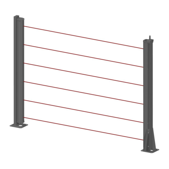
MIRIS 3000 / 3100 GENERALITES Les barrières à infrarouge actif MIRIS 3000 / MIRIS 3100 sont des systèmes de surveillance extérieure à hautes performances. Elles sont à installer en vis à vis sur la distance à protéger, ceci constituant une zone de détection immatérielle et invisible. -
Page 4: Description
SORHEA MIRIS 3000 / 3100 DESCRIPTION MIRIS 3000 : Bloc gestion Esclave 3 Bloc gestion Esclave 2 Batterie 12V (en option) Bloc gestion Maitre Cellule infrarouge Alimentation 230V AC / 110V AC Capot (en option) infrarouge Bloc gestion Esclave 1... - Page 5 SORHEA MIRIS 3000 / 3100 MIRIS 3100 : Colonne Simple Face (SF) Colonne Double Face (DF) Chapeau Anti-appui intégré Bloc gestion Esclave 3 Bloc gestion Esclave 2 Batterie 12V (en option) Bloc gestion Maitre Cellule infrarouge Alimentation 230V AC / 110V AC...
-
Page 6: Precautions De Mise En Oeuvre
SORHEA MIRIS 3000 / 3100 Description option alimentation 230V AC / 110V AC : Voyant vert présence 12V DC Voyant rouge présence chauffage Jumper de coupure du 12V DC Fusible automobile Nota : en cas de coupure 5A 32V pour batterie 230VAC, le système de... -
Page 7: Installation
SORHEA MIRIS 3000 / 3100 INSTALLATION Installation des colonnes MIRIS 3000 Quelle que soit la fixation utilisée, il est nécessaire de monter les entretoises à l'arrière du châssis afin de dégager assez de place pour le démontage du capot. Entretoise... - Page 8 SORHEA MIRIS 3000 / 3100 Montage du capot infrarouge 1. Engager le capot sur l’arceau du haut de la colonne de manière à ce que le capot s’ouvre, et s’engage dans les rainures du châssis (en faisant attention à ne pas désorienter les cellules).
- Page 9 SORHEA MIRIS 3000 / 3100 Détail du scellement du poteau Sceller les 4 tiges d'ancrage dans un massif béton en prenant soin de les positionner bien verticalement à l'aide du gabarit de scellement fourni. Bien positionner le scellement du poteau en fonction de l’orientation des faisceaux.
-
Page 10: Installation Des Colonnes Miris 3100
SORHEA MIRIS 3000 / 3100 Installation des colonnes MIRIS 3100 Fixation murale : voir notice fournie avec les jeux de brides Détail du scellement de l’embase Sceller les 4 tiges d'ancrage dans un massif béton en prenant soin de les positionner bien verticalement à... - Page 11 SORHEA MIRIS 3000 / 3100 Démontage du capot infrarouge Montage du capot infrarouge - 10 -...
-
Page 12: Positionnement D'une Colonne Dans Un Angle
SORHEA MIRIS 3000 / 3100 Positionnement d’une colonne dans un angle En cas d’installation de colonne en angle, orienter la colonne parallèlement au mur. Mauvaise installation de la colonne en angle Embase Colonne en angle Installation correcte de la colonne en angle... -
Page 13: Selection Des Canaux
SORHEA MIRIS 3000 / 3100 SELECTION DES CANAUX Afin d’éviter que les différentes barrières d’un même site ne se perturbent entre elles, celles-ci sont munies de 4 fréquences sélectionnables (canaux). Deux colonnes associées doivent être configurés avec le même numéro de canal. Cette configuration se fait à... -
Page 14: Raccordement
Relais Intrusion Zone 2 C Relais disqualification Zone 2 NO Relais disqualification Zone 2 C * Câblage uniquement du C.A.A. pour les MIRIS 3000 Pour les MIRIS 3100, le Chapeau Anti-Appui intégré est précâblé dans ces bornes. - 13 -... -
Page 15: Raccordement En 230Vac (Alimentation En Option)
Relais Intrusion Zone 2 C Relais disqualification Zone 2 NO Relais disqualification Zone 2 C * Câblage uniquement du C.A.A. pour les MIRIS 3000 Pour les MIRIS 3100, le Chapeau Anti-Appui intégré est précâblé dans ces bornes. - 14 -... -
Page 16: Raccordement Pour Colonnes Double Face (Df)
Relais disqualification Zone 1 C Relais disqualification Zone 2 C Chauffage 12Vac-dc Chauffage 12Vac-dc Alimentation 12Vdc Alimentation 12Vdc * Câblage uniquement du C.A.A. pour les MIRIS 3000 Pour les MIRIS 3100, le Chapeau Anti-Appui intégré est précâblé dans ces bornes. - 15 -... - Page 17 Relais disqualification Zone 1 NO Relais disqualification Zone 2 C Relais disqualification Zone 1 C * Câblage uniquement du C.A.A. pour les MIRIS 3000 Pour les MIRIS 3100, le Chapeau Anti-Appui intégré est précâblé dans ces bornes. - 16 -...
-
Page 18: Longueur Maximum Des Câbles Pour L'électronique Alimentée En 12V Dc
SORHEA MIRIS 3000 / 3100 Longueur maximum des câbles pour l'électronique alimentée en 12V DC (Câble type SYT1) MIRIS 3000/3100 Nbre de Cellules 2 Cellules 4 Cellules 6 Cellules 8 Cellules Consommation fil Section fil Longueur maximale des câbles (m) (mm) (mm²) -
Page 19: Alignement Et Reglage
SORHEA MIRIS 3000 / 3100 ALIGNEMENT ET REGLAGE Alignement optique Le bon fonctionnement de la détection dépend de l'alignement de la barrière. Zone de détection Cet alignement consiste à faire coïncider les axes optiques des cellules des colonnes installées en vis à... -
Page 20: Optimisation De L'alignement
SORHEA MIRIS 3000 / 3100 Optimisation de l’alignement Bloc gestion « Master » : Switch 1 et 2 : Switch 5 : Sélection de canal Mode de fonctionnement Réglage du temps CHANNEL MODE DELAY de réponse Bouton poussoir « SELECT » : Voyant rouge «... -
Page 21: Temps De Réponse
SORHEA MIRIS 3000 / 3100 Temps de Réponse Régler le temps de réponse de l'alarme intrusion de la colonne en agissant sur le potentiomètre du module « Maître ». Ceci permet d'adapter la sensibilité de détection de la barrière à l'environnement. Un temps de réponse long diminue la sensibilité. -
Page 22: Selection Du Mode De Fonctionnement
SORHEA MIRIS 3000 / 3100 SELECTION DU MODE DE FONCTIONNEMENT Mode de détection Le mode de détection se configure sur le bloc gestion « Maître » : Switch 5 du bloc gestion « Maitre » sur ON pour activer la bi-détection. -
Page 23: Mono-Détection Sur Faisceau Bas (Optionnel)
SORHEA MIRIS 3000 / 3100 Mono-détection sur faisceau bas (optionnel) La colonne doit être configurée en bi-détection pour pouvoir activer le faisceau bas en mono- détection. La mono-détection sur le faisceau bas génère une alarme intrusion lorsque le faisceau bas est coupé... -
Page 24: Maintenance
SORHEA MIRIS 3000 / 3100 MAINTENANCE Pour assurer un maintien des performances dans le temps, il faut prévoir un entretien minimum : - Nettoyer le capot de chaque élément au moins une fois par an. (ou plus suivant exposition aux salissures) Dépannage... -
Page 25: Configuration Des Modules Par Défaut
SORHEA MIRIS 3000 / 3100 Configuration des modules par défaut Type de Position Configuration des switchs module 1 2 3 4 5 Position 4 Position 4 Esclave 3 Switch 1 sur ON CHANNEL MODE Switch 2 sur ON Switch 3 sur OFF... -
Page 26: Caracteristiques Techniques
SORHEA MIRIS 3000 / 3100 CARACTERISTIQUES TECHNIQUES Distance maximum de protection en utilisation 250 m intérieure Distance maximum de protection en utilisation 100 m extérieure Faisceaux infrarouge multiplexés Type de détection Longueur d'onde 950 nm Nombre de cellules 2 à 8, regroupé par module de 2 cellules Mode de détection... - Page 27 SORHEA MIRIS 3000 / 3100 Dimensions : Colonne MIRIS 3000 Colonne MIRIS 3100 SF Colonne MIRIS 3100 DF MIRIS 3000 Hauteur de la colonne (H) 1M10 1,115 m 1M90 1,915 m 2M50 2,515 m 3,015 m MIRIS 3100 Hauteur de la colonne (H)
-
Page 28: References Des Produits
SORHEA MIRIS 3000 / 3100 REFERENCES DES PRODUITS 11.1 Pièces de rechange Electronique : Bloc gestion 80901601 réf : Cellule mixte 80900405 réf : Kit alimentation 230V AC / 110V AC 30541101 réf : Mécanique MIRIS 3000 : ... - Page 29 GENERAL ......................29 DESCRIPTION ....................30 PRECAUTIONS REGARDING INSTALLATION ..........32 INSTALLATION ....................33 Installation of MIRIS 3000 columns ..................33 Installation of MIRIS 3100 column ..................36 Positioning for a column in a corner ..................38 SELECTING THE CHANNELS ................39 WIRING .......................
-
Page 30: General
SORHEA MIRIS 3000 / 3100 GENERAL Active infrared barriers MIRIS 3000 / MIRIS 3100 are high performance exterior surveillance systems. They are installed facing each other over the distance to be protected, creating an immaterial and invisible detection zone. The simultaneous interruption of two adjacent beams triggers an intrusion. -
Page 31: Description
SORHEA MIRIS 3000 / 3100 DESCRIPTION MIRIS 3000: Slave 3 Control Unit Slave 2 Control Unit 12V Battery (Optional) Master Control Unit Infrared cell infrarouge Power 230V AC / 110V AC Infrared (Optional) cover Slave 1 Control Unit Terminal Block... - Page 32 SORHEA MIRIS 3000 / 3100 MIRIS 3100: Single-Face column (SF) Double-Face column (DF) Integrated Anti-Climb Cap Slave 3 Control Unit Slave 2 Control Unit 12V Battery (Optional) Master Control Unit Infrared cell Power 230V AC / 110V AC (Optional) Slave 1...
-
Page 33: Precautions Regarding Installation
SORHEA MIRIS 3000 / 3100 Description of optional power unit 230V AC / 110V AC: Green led indicates 12V DC on Red led indicates heater on Shut-off jumper for 12V DC Automotive fuse Note: in case of 230V AC failure,... -
Page 34: Installation
SORHEA MIRIS 3000 / 3100 INSTALLATION Installation of MIRIS 3000 columns For every type of installation, it is important to place spacers at the back of the frame in order to keep enough space for cover removal. Spacer Cover Support Frame ... - Page 35 SORHEA MIRIS 3000 / 3100 Reinstallation oh the infrared cover 1. Attach the cover on the curved top of the housing so that the cover can open the column, and is inserted in the grooves of the housing. (be careful not to change the orientation of the cells) 2.
- Page 36 SORHEA MIRIS 3000 / 3100 Detail for pole-mounted columns Seal the 4 anchor rods in solid concrete, taking care to install them in a vertical position using the provided sealing template. Position the floor socket seal so that it is oriented the same way as the beam.
-
Page 37: Installation Of Miris 3100 Column
SORHEA MIRIS 3000 / 3100 Installation of MIRIS 3100 column Wall mounting: see notice provided with brackets Detail for floor socket Seal the 4 anchor rods in solid concrete, taking carte to install them in a vertical position using the provided sealing template. - Page 38 SORHEA MIRIS 3000 / 3100 Removing the infrared cover Installing the infrared cover - 37 -...
-
Page 39: Positioning For A Column In A Corner
SORHEA MIRIS 3000 / 3100 Positioning for a column in a corner In the event a column is to be installed in a corner, orient the column parallel to the wall. Incorrect installation of a column in a corner Wall... -
Page 40: Selecting The Channels
SORHEA MIRIS 3000 / 3100 SELECTING THE CHANNELS To prevent barriers on the same site from interfering with each other, the barriers are equipped with 4 selectable frequencies (channels). Two connected columns must be configured with the same channel number. The configuration is done using switches 1 and 2 located on the “MASTER”... -
Page 41: Wiring
Intrusion relay Zone 2 C Disqualification relay Zone 2 NO Disqualification relay Zone 2 C * wiring a nti-climb cap for MIRIS 3000 only. For MIRIS 3100, the integrated a nti-climb cap is pre-wired to the terminals. - 40 -... -
Page 42: Connecting The 230Vac Power Supply (Optional)
Intrusion relay Zone 2 C Disqualification relay Zone 2 NO Disqualification relay Zone 2 C * wiring a nti-climb cap for MIRIS 3000 only. For MIRIS 3100, the integrated a nti-climb cap is pre-wired to the terminals. - 41 -... -
Page 43: Connecting The Double-Face Column (Df)
Disqualification relay Zone 1 C Disqualification relay Zone 2 C Heater 12Vac-dc Heater 12Vac-dc Power 12Vdc Power 12Vdc * wiring a nti-climb cap for MIRIS 3000 only. For MIRIS 3100, the integrated a nti-climb cap is pre-wired to the terminals. - 42 -... - Page 44 Disqualification relay Zone 1 NO Disqualification relay Zone 2 C Disqualification relay Zone 1 C * wiring a nti-climb cap for MIRIS 3000 only. For MIRIS 3100, the integrated a nti-climb cap is pre-wired to the terminals. - 43 -...
-
Page 45: Maximum Cable Lengths For Electronic Circuits Supplied With 12V Dc
SORHEA MIRIS 3000 / 3100 6.4 Maximum cable lengths for electronic circuits supplied with 12V DC. (Wire type SYT1 shielded) MIRIS 3000/3100 Number of Cells 2 Cells 4 Cells 6 Cells 8 Cells Consumption (mA) Wire Wire Maximum cable lengths... -
Page 46: Alignment And Ajustement
SORHEA MIRIS 3000 / 3100 ALIGNMENT AND AJUSTEMENT Optical alignment For detection to function correctly it is essential that the alignment of the barrier is optimized. Detection zone This alignment consist of lining up the optical axis of the cells of the barriers facing each other. This alignment adjustment is performed initially for each cell by using the integrated sighting system. -
Page 47: Optimization Of Alignment
SORHEA MIRIS 3000 / 3100 Optimization of alignment “Master” Control Unit: Switches 1 and 2: Switch 5: Channel selection Operating mode Setting the CHANNEL MODE DELAY response time Push button “SELECT”: Red light “ALARM”: Barrier alignment Intrusion alarm 1. Connect the column modules to main power. -
Page 48: Response Time
SORHEA MIRIS 3000 / 3100 Response time Adjust response time of the intrusion alarm using the potentiometer of the Master module. Adjustment of the response time allow adaptation of the detection sensitivity of the barrier to the environment. A long response time reduces the sensitivity. -
Page 49: Selecting The Operation Mode
SORHEA MIRIS 3000 / 3100 SELECTING THE OPERATION MODE Detection mode Detection mode is configured on the “Master” Control Unit: To activate dual-beam detection, set switch 5 of the “Master” Control Unit to ON. To activate mono-beam detection, set switch 5 of the “Master” Control Unit to OFF. -
Page 50: Mono-Beam On Bottom Cell (Optional)
SORHEA MIRIS 3000 / 3100 Mono-beam on bottom cell (optional) The column needs to be set to dual-beam in order to activate the mono-beam on the bottom cell. Mono-beam on the bottom cell triggers an intrusion alarm when the bottom cell beam is cut for 1.5 seconds. -
Page 51: Maintenance
SORHEA MIRIS 3000 / 3100 MAINTENANCE To maintain performance over time, a minimum of maintenance must be performed: - Clear the cover of each device at least once a year (on more often following exposure to dirt) Troubleshooting Malfunction Probable causes Solutions ... -
Page 52: Default Module Configuration
SORHEA MIRIS 3000 / 3100 Default module configuration Module Position Configuration of switches type 1 2 3 4 5 Position 4 Position 4 Slave 3 Switch 1 to ON CHANNEL MODE Switch 2 to ON Switch 3 to OFF Switch 4 to ON... -
Page 53: Technical Specifications
SORHEA MIRIS 3000 / 3100 TECHNICAL SPECIFICATIONS 250 m / 820 ft Maximum indoor detection distance 100 m / 328 ft Maximum outdoor detection distance Multiplexed infrared beams Type of detection Wave length 950 nm Number of cells 2 to 8, grouped into modules of 2 cells... - Page 54 SORHEA MIRIS 3000 / 3100 Dimensions: MIRIS 3000 MIRIS 3100 SF MIRIS 3100 DF 120 mm 160 mm 250 mm 4,6 in 6,4 in 9,7 in MIRIS 3000 Column height (H) 1.10 m / 3.6 ft 1,115 m / 3.66 ft 1.90 m / 6.2 ft...
-
Page 55: Product References
SORHEA MIRIS 3000 / 3100 PRODUCT REFERENCES 11.1 Spare parts Electronic parts: Control Unit ref: 80901601 Mixed cell ref: 80900405 Power unit 230V AC / 110V AC ref: 30541101 Mechanical parts MIRIS 3000: Column cover 1.10 m / 3.6 ft ref: 80900121 ...