Table des Matières
Publicité
Les langues disponibles
Les langues disponibles
Liens rapides
SOLARIS
BARRIERE AUTONOME A INFRAROUGE ACTIF
FR
Notice d'installation -
Pages 1-27
AUTONOMOUS WIRELESS INFRARED BARRIER
EN
Installation manual -
Pages 28-54
1, rue du Dauphiné – 69120 – VAULX-EN-VELIN – FRANCE
Tél. : +33(0)4.78.03.06.10 - Fax : +33(0)4.78.68.24.61
Site web :
www.sorhea.com
Email :
commercial@sorhea.fr
NT261 / V2.4 / 02.15
Publicité
Table des Matières

Manuels Connexes pour SORHEA SOLARIS


Sommaire des Matières pour SORHEA SOLARIS
- Page 1 SOLARIS BARRIERE AUTONOME A INFRAROUGE ACTIF Notice d’installation - Pages 1-27 AUTONOMOUS WIRELESS INFRARED BARRIER Installation manual - Pages 28-54 1, rue du Dauphiné – 69120 – VAULX-EN-VELIN – FRANCE Tél. : +33(0)4.78.03.06.10 - Fax : +33(0)4.78.68.24.61 Site web : www.sorhea.com...
-
Page 2: Table Des Matières
SORHEA SOLARIS SOMMAIRE GENERALITES ....................2 DESCRIPTION ....................3 PRECAUTIONS DE MISE EN OEUVRE ............. 4 INSTALLATION ....................5 Dimensions de l’embase ......................5 Montage de l’option 2 plots béton enterrés pour colonne 1M50 et 2M ........6 Montage de l’option 3 plots béton enterrés pour colonne 2M50 et 3M ........7 Montage de la colonne sur l’embase .................. -
Page 3: Generalites
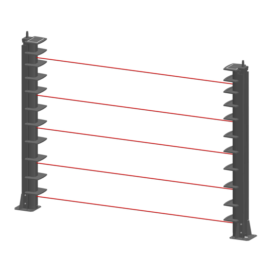
L’alimentation se compose d’un panneau solaire et d’un pack batterie assurant une autonomie tout temps. Les barrières à infrarouge actif SOLARIS génèrent une information d’alarme sur coupure de deux cellules adjacentes. Elles se composent d’une colonne émission (TX) et d’une colonne réception (RX) à... -
Page 4: Description
SORHEA SOLARIS DESCRIPTION Chapeau anti-appui Panneau solaire intégrant l’antenne radio Carte radio Cellule 8 Cellule 7 Cellule 6 Bloc gestion 2 (Cellule 6 à 8) Cellule 5 Bloc gestion 1 (Cellule 1 à 5) Cellule 4 Casquette pare rosée Cellule 3... -
Page 5: Precautions De Mise En Oeuvre
SORHEA SOLARIS PRECAUTIONS DE MISE EN OEUVRE Afin de bien installer les barrières, il est important de respecter certaines règles. Ne pas disposer de cellules face aux rayons solaires directs 5° mini Avoir un support stable Vérifier qu'aucune végétation ne puisse masquer... -
Page 6: Installation
SORHEA SOLARIS Déporter le panneau solaire Lorsqu’une colonne SOLARIS doit être installée contre un mur supérieur à 5m de haut et orienté plein nord, déporter le panneau solaire en haut du mur. INSTALLATION Dimensions de l’embase Embase courte pour Embase longue pour... -
Page 7: Montage De L'option 2 Plots Béton Enterrés Pour Colonne 1M50 Et 2M
Montage de l’option 2 plots béton enterrés pour colonne 1M50 et 2M Dimensions de l’option 2 plots béton Hauteur d’enfouissement des plots béton Ecrou M16 Embase SOLARIS 1M50 / 2M Rondelle Ø16 Ecrou M16 Plot béton Rondelle Ø16 Assembler l’option Ecrou M16 pour réglage... -
Page 8: Montage De L'option 3 Plots Béton Enterrés Pour Colonne 2M50 Et 3M
Montage de l’option 3 plots béton enterrés pour colonne 2M50 et 3M Dimensions de l’option 3 plots béton Hauteur d’enfouissement des plots béton Ecrou M16 Embase SOLARIS 2M50 / 3M Rondelle Ø16 Ecrou M16 Plot béton Rondelle Ø16 Ecrou M16 pour réglage Assembler l’option... -
Page 9: Montage De La Colonne Sur L'embase
SORHEA SOLARIS Montage de la colonne sur l’embase Vis M8 Eclisses Rondelle Ø8 Monter les éclisses sur l’embase sans les bloquer. Nota : L’éclisse ne doit pas dépasser de l’embase. Faire coulisser la Embase colonne entre les deux montants de l’embase. -
Page 10: Démontage Du Capot Infrarouge
SORHEA SOLARIS Installation correcte de la colonne en angle Démontage du capot infrarouge Dévisser la vis Descendre le capot Dégager le capot - 9 -... -
Page 11: Montage Du Panneau Solaire
SORHEA SOLARIS Montage du panneau solaire 4.6.1 Déport du panneau solaire Distance maximale du déport : 75m Faire passer le câble du panneau solaire directement par le bas de la colonne 4.6.2 Installation du panneau solaire Panneau solaire Visser le panneau Câble du... - Page 12 SORHEA SOLARIS Cas d’une colonne double face : Colonne de 1M50 et 2M : Clipser et visser une 2 casquette sans panneau solaire sur la 2 face Colonne de 2M50 et 3M : Clipser et visser une 2 casquette avec panneau solaire sur la 2...
-
Page 13: Raccordement Du Panneau Solaire
SORHEA SOLARIS 4.6.3 Raccordement du panneau solaire Nota : en cas d’utilisation de 2 panneaux solaire, câbler 1 panneau solaire sur chaque face de la colonne DF en suivant les opérations ci-dessous. Remonter le câble dans la rainure de droite jusqu’au bloc gestion... -
Page 14: Alignement Et Reglage
SORHEA SOLARIS Descendre la colonne sur l’embase et serrer les vis de l’embase. ALIGNEMENT ET REGLAGE Branchement du pack batterie Connecter le pack batterie en branchant le fil rouge sur la borne + du pack batterie Sélection des canaux Afin d’éviter que les différentes barrières d’un même site ne se perturbent entre elles, celles-ci sont munies de 4 canaux infrarouge. -
Page 15: Validation Du Paramétrage
SORHEA SOLARIS Canal 1 Canal 2 Canal 3 Canal 4 Attribution des canaux en fonction de la disposition des colonnes ayant 5 faisceaux maximum par barrière. Canal 1 Canal 3 Canal 2 Canal 4 Canal 2 Canal 4 Canal 1... -
Page 16: Alignement
SORHEA SOLARIS Alignement Alignement optique Le bon fonctionnement de la barrière dépend directement de son alignement. L’alignement consiste à faire coïncider les axes optiques de chaque cellule des colonnes installées en vis à vis. Il se fait cellule par cellule sur chacune des colonnes TX et RX. - Page 17 SORHEA SOLARIS Passage en mode réglage Règles à respecter : 1. L’alignement consiste à rechercher la position donnant le maximum de signal pour la puissance minimale (potentiomètre de puissance du faisceau). Signal Signal max. Position 2. Les colonnes TX et RX doivent être toutes les deux en mode alignement.
- Page 18 SORHEA SOLARIS Etape : Colonne RX Colonne TX Régler le potentiomètre de la puissance du faisceau au maximum. Appuyer sur le bouton poussoir « Select » pendant plus de 2s jusqu’à ce que le buzzer émette 3 bips courts. (l’alignement commence à la cellule 1) Appuyer sur le bouton poussoir «...
-
Page 19: Paramétrage
SORHEA SOLARIS Paramétrage Paramétrage du temps de réponse de l'alarme intrusion Régler le temps de réponse en agissant sur le potentiomètre du bloc gestion réception (RX). Temps de 40 ms 200 ms 400 ms 550 ms 800 ms réponse ... -
Page 20: Mise En Place Des Casquettes Pare Rosee
SORHEA SOLARIS MISE EN PLACE DES CASQUETTES PARE ROSEE Nota : le montage des casquettes pare rosée sur les supports casquettes ne se fait que lors de la première installation. Clipser les casquettes pare-rosée juste Montage ok au-dessus de chaque cellule. -
Page 21: Transmission Des Alarmes
SORHEA SOLARIS En fin de montage les casquettes pare-rosée et leurs supports forme un ensemble homogène démontable et remontable en une seule opération. Montage de la casquette embase pour les colonnes 2M50 et 3M Positionner la casquette embase au-dessus de la cellule et serrer les vis. -
Page 22: Tests Finaux
SORHEA SOLARIS Les adresses réseau des blocs gestion et l’identifiant « ID » de la radio de chaque colonne doivent être repérés sur un plan afin de paramétrer l’affectation des alarmes sur le concentrateur MAXIBUS III. (voir notice NT297 du concentrateur MAXIBUS III) Exemple : L’alarme intrusion zone 1 est détectée par le bloc gestion RX adresse 3 et transmise au... -
Page 23: Fermeture De La Colonne
SORHEA SOLARIS FERMETURE DE LA COLONNE Nota : toutes les étapes d’ouverture et de fermeture de la colonne se trouvent en fin de notice. Démontage du capot support casquettes pare rosée Retirer les vis de fixation Démontage de la casquette embase... -
Page 24: Montage Du Capot Infrarouge
SORHEA SOLARIS Montage du capot infrarouge Engager le capot dans les rainures en s’aidant de l’arceau guide en haut de la colonne Fermer le capot avec la vis. Plaquer le capot sur Monter le capot la flasque basse. jusqu’en butée... -
Page 25: Montage Du Capot Support Casquettes Pare Rosée
SORHEA SOLARIS Montage du capot support casquettes pare rosée Remonter le capot avec les vis de fixation. Remontage de la casquette embase (uniquement pour les colonnes 2M50 et 3M) Descendre la casquette embase jusqu’à la marque faite sur l’embase. Serrer les vis... -
Page 26: Maintenance
SORHEA SOLARIS MAINTENANCE Défaut constaté Cause probable Solution Tension batterie faible. Tension batterie < 3.85V Au démarrage de la colonne, le buzzer émet un bip long (5s). (Panneau déconnecté ou (reset effectué avec le cavalier recouvert, renouveler le pack «... -
Page 27: Caracteristiques Techniques
SORHEA SOLARIS CARACTERISTIQUES TECHNIQUES SOLARIS Portée maximum en extérieur 75 m Type de détection Faisceaux infrarouge pulsés suivant 4 canaux. Nombre de cellules pour 1 direction 3 à 10 Mode de détection Bi-détection temporisée Temps de réponse de l’alarme intrusion réglable de 40ms à... -
Page 28: References Des Options
SORHEA SOLARIS REFERENCES DES OPTIONS Panneau solaire supplémentaire réf : 30620902 Option fixation murale pour colonne SF 1M50 et 2M réf : 30580002 Option fixation murale pour colonne DF 1M50 et 2M réf : 30580021 Option fixation murale pour colonne SF 2M50 et 3M réf : 30621501... - Page 29 SORHEA SOLARIS CONTENTS INTRODUCTION ....................29 DESCRIPTION ....................30 INSTALLATION PRECAUTIONS ..............31 INSTALLATION ....................32 Dimensions of the template....................32 Mounting the 2 buried concrete blocks option for columns 1.5 m / 5 ft and 2 m / 7 ft ... 33 Mounting the 3 buried concrete blocks option for columns 2.5 m / 8.2 ft and 3 m / 10 ft ..
-
Page 30: Introduction
Power is supplied thanks to an integrated solar panel and battery pack that guarantee the column’s autonomy in all weathers. The active infrared barriers SOLARIS generate alarm information when 2 parallel cells are cut. They consist of a transmitter column (TX) and a receiver column (RX) to be installed face to face and at the distance that is to be protected. -
Page 31: Description
SORHEA SOLARIS DESCRIPTION Anti-climbing cap and integrated radio Solar panel antenna Radio board Cell 8 Cell 7 Cell 6 Control board 2 (Cell 6 to 8) Cell 5 Anti-ice and Control board 1 anti-condensation (Cell 1 to 5) Cell 4... -
Page 32: Installation Precautions
SORHEA SOLARIS INSTALLATION PRECAUTIONS To install the barriers correctly, it is important to follow certain rules. Do not position the cells facing direct sunlight 5° minimum Have a stable support Be sure that beams cannot be obscured by vegetation in any season... -
Page 33: Installation
SORHEA SOLARIS Deport the solar panel When a column SOLARIS has to be installed against a wall higher than 5m / 16 ft and north facing, deport the solar panel on the top of the wall. INSTALLATION Dimensions of the template 200 mm / 7.9 in... -
Page 34: Mounting The 2 Buried Concrete Blocks Option For Columns 1.5 M / 5 Ft And 2 M / 7 Ft
Burying height of 15.75 in the concrete 200 mm 100 mm blocks 7.87 in 3.94 in Floor socket SOLARIS 1.50 m / 5 ft Nut M16 and 2 m / 7 ft Washer Ø16 Nut M16 Concrete block Washer Ø16 Assemble the... -
Page 35: Mounting The 3 Buried Concrete Blocks Option For Columns 2.5 M / 8.2 Ft And 3 M / 10 Ft
100 mm 200 mm 3.94 in 7.87 in 400 mm 15.75 in Nut M16 Floor socket SOLARIS Washer Ø16 2.5 m / 8.2 ft and 3 m / 10 ft Nut M16 Concrete block Washer Ø16 Nut M16 for adjustment... -
Page 36: Mounting The Column On The Floor Socket
SORHEA SOLARIS Mounting the column on the floor socket Screw M8 Guides Washer Ø8 Put the guides on the floor socket without blocking them. Note: The guides must not go beyond the floor socket. Slide the column Template between the 2 pillars of the floor socket. -
Page 37: Remove The Cover
SORHEA SOLARIS Correct installation of the column in a corner Remove the cover Unscrew the screw Push the cover to the top Pull the cover away - 36 -... -
Page 38: Mounting The Solar Panel
SORHEA SOLARIS Mounting the solar panel 4.6.1 Deport of the solar panel 138 mm / 5.4 in Maximum distances of deport: 75 m / 246 ft Pass the cable from the solar panel directly to the bottom of the column 4.6.2 Solar panel installation... - Page 39 SORHEA SOLARIS For a double face column: Columns 1.5 m / 5 ft and 2 m / 7 ft: Clip and screw in a 2 cap without solar panel on 2 face Columns 2.5 m / 8.2 ft and 3 m / 10 ft:...
- Page 40 SORHEA SOLARIS 4.6.3 Connecting the solar panel Note: in case 2 solar panels are used, wire 1 solar panel on each face of the DF column as follows: Put the cable in the right rail to the control board Pull the needle to make the cable of the solar panel go down.
-
Page 41: Alignment And Adjustment
SORHEA SOLARIS Lower down the column on the floor socket and fasten the screws. ALIGNMENT AND ADJUSTMENT Connecting the battery pack Connect the battery pack by wiring the red wire on the terminal + of the battery pack Channel selection To prevent interference by one barrier with another at the same site, barriers are equipped with four selectable frequencies (channels). -
Page 42: Validation Of The Configuration
SORHEA SOLARIS Channel 1 Channel 2 Channel 3 Channel 4 Assignment of channels according to column availability having 5 cells maximum per barrier. Channel 1 Channel 3 Channel 2 Channel 4 Channel 2 Channel 4 Channel 1 Channel 3 Assignment of channels according to column availability having 6 cells maximum per barrier. -
Page 43: Optical Alignment
SORHEA SOLARIS Alignment Optical alignment Efficient detection depends on the correct alignment of the barrier. This alignment consists of lining up the optical axes of the column cells installed facing each other. It is to be done cell by cell on each TX and RX column. -
Page 44: Adjustment Mode
SORHEA SOLARIS Adjustment mode Rules to follow: 1. The alignment consists in finding the position that gives the maximum signal for the minimum power (power potentiometer of the beam). Signal max. signal Position 2. The TX and RX columns must both be in alignment mode. - Page 45 SORHEA SOLARIS Stage: RX column TX column Adjust the power potentiometer of the beam to the maximum. Push the button “Select” for more than 2s until the buzzer signal makes 3 short beeps. (the alignment starts with cell 1) Push the button “Select” more than 2s until the buzzer signal makes 3 short beeps.
-
Page 46: Configuration
SORHEA SOLARIS Configuration Configuration of response time for the intrusion alarm Adjust the response time by moving the potentiometer of the receiver control board (RX). Response 40 ms 200 ms 400 ms 550 ms 800 ms time Bottom cell selection Validate / invalidate the mono detection of the time-delayed lower cell to 1,5s (not adjustable) by setting switch 1 on the ON position. -
Page 47: Mounting The Anti-Ice And Anti-Condensation Caps
SORHEA SOLARIS MOUNTING THE ANTI-ICE AND ANTI-CONDENSATION CAPS Note: mounting the anti-ice and anti-condensation caps in their support will only be done during the installation. Clip the caps just above each Correct mounting cell. Screw in the caps. Wrong mounting: caps are placed too Position of the caps for a cell inclination of +/-10°:... -
Page 48: Alarm Transmission
SORHEA SOLARIS When the anti-ice and anti-condensation caps are mounted on their frame, it forms an homogeneous unit that can be taken off and put on as one single piece. Mounting the metallic cap for columns 2.5 m / 8.2 ft and 3 m / 10 ft... -
Page 49: Final Tests
SORHEA SOLARIS The network addresses of the control boards and the « ID » of the radio of each column must be spotted on a plan to configure the alarms assignment on the MAXIBUS III Hub. (See NT297 of the MAXIBUS III Hub) Example: The intrusion alarm zone 1 is detected by the RX column address 3 and transmitted to the MAXIBUS III Hub via the radio ID 425. -
Page 50: Closing The Column
SORHEA SOLARIS CLOSING THE COLUMN Note: all the steps to open and close the column are at the end of manual. Removing the anti-ice and anti-condensation caps cover Pull out the 4 mounting screws Removing the metallic cap (Only for columns 2.5 m / 8.2 ft and 3 m / 10 ft) -
Page 51: Mounting The Cover
SORHEA SOLARIS Mounting the cover Mount the cover into the rails of the frame with the help of the guide bolts on top of the column Close the cover with the screw. Put back the cover Push the cover on the flange. -
Page 52: Mounting The Cover With The Caps
SORHEA SOLARIS Mounting the cover with the caps Replace the cover with the 4 mounting screws Remounting the metallic cap (Only for columns 2.5 m / 8.2 ft and 3 m / 10 ft) Lower down the metallic cap to the mark on the floor socket. -
Page 53: Maintenance
SORHEA SOLARIS MAINTENANCE Malfunction Probable cause Solution Low battery tension. Battery tension < 3.85V When the column is powered, the buzzer makes a long beep (5s). (The panel is disconnected or (Reset made with the “reset” covered, replace the battery jumper) pack). -
Page 54: Technical Specifications
SORHEA SOLARIS TECHNICAL SPECIFICATIONS SOLARIS Maximum outdoor range 75 m / 246 ft Pulsed infrared cells with four selectable frequencies Detection mode (channels). Number of cells for 1 direction 3 to 10 Detection mode Time-delayed dual-detection Response time of intrusion alarm... -
Page 55: Option References
SORHEA SOLARIS OPTION REFERENCES Additional solar panel ref: 30620902 Wall fixing option for SF column 1.5 m / 5 ft and 2 m / 7 ft ref: 30580002 Wall fixing option for DF column 1.5 m / 5 ft and 2 m / 7 ft ref: 30580021 ...