
Manuels Connexes pour Heidolph 1000


Sommaire des Matières pour Heidolph 1000
- Page 1 INKUBATOR 1000 Betriebsanleitung Instruction Manual Mode d’Emploi Instrucciones de Empleo Istruzioni per l’uso...
- Page 2 DEUTSCH Seite 3 – 14 ENGLISH page 15 – 26 FRANCAISE page 27 – 38 lESI ESPAÑOL página 39 – 50 ITALIANO Pagina 51 – 62...
-
Page 3: Table Des Matières
Wir danken Ihnen für den Kauf dieses Gerätes. Sie haben ein Produkt erworben, das von der Firma Heidolph nach DIN EN ISO 61010 gefertigt und geprüft wurde. Mit diesem Gerät werden Sie Ihre Arbeit einwandfrei und problemlos durchführen können. INHALT INHALT ..........................3... -
Page 4: Lieferumfang Und Zubehör
LIEFERUMFANG UND ZUBEHÖR Bezeichnung Menge Bestellnummer Bestellnummer 230/240V / 115V / 50/60Hz 50/60Hz INKUBATOR 1000 Heizmodul 549-90010-00 549-90020-00 Inkubationshaube flach 549-90040-00 549-90040-00 (bestehend aus: Oberteil, Unterteil, Luftleitscheibe flach) oder Inkubationshaube hoch alternativ 549-90030-00 549-90030-00 (bestehend aus: Oberteil, Unterteil, Luftleitscheibe hoch) -
Page 5: Sicherheitshinweise
Vor Inbetriebnahme des Gerätes ist das Schüttelgut sicher und unverrückbar zu befestigen. AUFBAU Der INKUBATOR 1000, bestehend aus einem Heizmodul und einer Haube. Zusammen mit den unten angeführten Schüttel- und Mischgeräten kann er modular kombiniert werden. Er dient zum Temperieren von mit Proben gefüllen Gefäßen während des Schüttelvorganges. - Page 6 ♦ Halteblech (E) mit den 2 mitgelieferten Schrauben und Federringen unten an das Heizmodul (B) montieren. ♦ Das Heizmodul (B) rechts neben das Schüttelgerät (A) stellen. ♦ Das Schüttelgerät mit den Gummifüßen in die Löcher des Haltebleches (E) plazieren. ♦ Das Unterteil (C) der 2-teiligen Haube auf das Schüttelgerät und das Heizmodul setzen. Dabei gegebenenfalls Schütteltisch von Hand bewegen, damit die Ausschnitte des Unterteils (C) sich über den Schütteltisch fügen lassen.
- Page 7 ♦ Das Unterteil (C) mit 2 der mitgelieferten Rändelschrauben (G) am Heizmodul befestigen. ♦ Der 3. Befestigungspunkt ist an der linken Seitenwange des Schüttelgerätes (N). Die 3. mitgelieferte Rändelschraube (G1) in die Gewindebohrung (N) an der Seitenwange des Schüttelgerätes drehen und festziehen. Das Unterteil (C) ist nun befestigt.
- Page 8 ♦ Die Haube (D) auf das montierte Unterteil setzen. ♦ Dazu vorher die Befestigungsschrauben (H) der Haube durch Linksdrehen etwa 6 mm öffnen und die Scharniere (J) in eine senkrechte Position bringen. Beim Aufsetzen der Haube (D) den Gewindeteil der Befestigungsschrauben (H) in den Schlitz der Scharniere (J) positionieren.
- Page 9 ♦ Griffteil (L) zum öffnen und schließen der Haube (D) benutzen. ♦ Im geschlossenen Zustand halten die in der Haube (D) integrierten Magnete (M) die Haube sicher geschlossen. Die Inkubationshaube hat Friktionsscharniere. Dadurch kann die Haube vom Anwender beliebig weit geöffnet werden und hält die Position bei jedem beliebigen Öffnungswinkel.
-
Page 10: Bedienung Und Betrieb
Es dürfen keine Gegenstände und Flüssigkeiten in die Schlitze des Heizmoduls gelangen. Es besteht die Gefahr, dass dabei der Lüfter bzw. die Heizung beschädigt werden. Heizmodul des Inkubator 1000 Von rechts nach links befinden sich folgende Bedienelemente auf der Bedienfront: A 2-poliger Netzschalter mit grüner beleuchteter Wippe... -
Page 11: Reinigung Und Wartung
Bestandteilen verwenden. Die Oberfläche des Gerätes würde dadurch Schaden erleiden. Das Gerät ist wartungsfrei. Eine eventuell notwendige Reparatur ist unbedingt von einem durch Heidolph autorisierten Fachmann auszuführen. Wenden Sie sich hierzu an Ihren HEIDOLPH-Händler bzw. an die HEIDOLPH-Vertretung. ABBAU, TRANSPORT UND LAGERUNG Abbau 1. -
Page 12: Entsorgung
Heizung abgekühlt ist, überprüfen, ob die Lüftungsschlitze unabsichtlich verdeckt sind. 3. Defekt an Elektronik (Anzeigen leuchten nicht). TECHNISCHE DATEN INKUBATOR 1000 Anschlußspannung 230/240 V 50/60 Hz optional 115 V 50/60 Hz Temperaturbereich 5 K über Raumtemperatur bis 65°C... -
Page 13: Garantie, Haftung Und Urheberrechte
Transportschäden sind ausgeschlossen. Im Falle eines Garantieanspruchs benachrichtigen Sie bitte Heidolph Instruments (Tel.: (+49) 9122 - 9920-69) oder Ihren Heidolph Instruments Händler. Wenn es sich um einen Material- oder Herstellungsfehler handelt, wird Ihnen im Rahmen der Garantie das Gerät kostenfrei repariert oder ersetzt. -
Page 14: Ce-Konformitätserklärung
Anschrift: Heidolph Instruments GmbH & Co. KG Vertrieb Labortechnik Walpersdorfer Str. 12 D-91126 Schwabach / Deutschland Tel.: +49 – 9122 - 9920-69 Fax: +49 – 9122 - 9920-65 E-Mail: sales@heidolph.de Sicherheitshinweis Bitte sorgen Sie bei der Anlieferung von Reparaturgeräten, die mit gefährlichen Arbeitsstoffen in Berührung gekommen sind für:... - Page 15 Thank you for purchasing a Heidolph Instruments product. This item has been designed, made and inspected in compliance with DIN EN ISO 61010 for long-term and flawless operation. SUMMARY SUMMARY...........................15 STANDARD HARDWARE & OPTIONS ................16 GENERAL INFORMATION ....................16 SAFETY INFORMATION.....................17 SET-UP ..........................17...
-
Page 16: Standard Hardware & Options
STANDARD HARDWARE & OPTIONS product quantity P/N 230/240V 50/60Hz 115V 50/60Hz INCUBATOR 1000 heater module 549-90010-00 549-90020-00 with incubator hood, flat, consisting 549-90040-00 549-90040-00 of: upper half, lower half, deflector plate, flat incubator hood, high, consisting optional 549-90030-00 549-90030-00 of: upper half, lower half,... -
Page 17: Safety Information
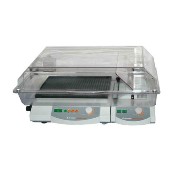
SET-UP The INCUBATOR 1000, consists of heater module and hood; it may be combined with shakers and mixers as stipulated below. The incubator heats fluids in whatever sort of vessel during shaking. The hood is made of clear plastic material to allow watching of vessels during shaking. - Page 18 ♦ Install holder (E) with two screws and spring washer from your hardware bag on bottom of heater module (B). ♦ Locate heater module on the right of shaker (A). ♦ Plug rubber feet of shaker in cutouts of holder. ♦...
- Page 19 ♦ The third attachment point is placed on the left hand side of the apparatus (N). Turn third knurled screw (G1) into thread (N) on left hand side and tighten. Lower part (C) is now secure.
- Page 20 ♦ Secure lower half (C) on heater module; use 2 ea. knurled bolts from your hardware bag. ♦ Place hood (D) on lower part.To do so loosen fastening screw (H) by turning counter- clockwise until gap is ca. 6mm. Align hinges to an upright position. While mounting hood (D) place threaded part of fastening screw (H) in slash of hinges (J).
-
Page 21: Operation And Controls
Maintain unobstructed circulation of air under hood.. Avoid entry of foreign matter or spilled fluids through ventholes in heater module. Negligence might damage fan (heater element). Incubator 1000, heating module The front panel features the following controls (from right to left):... -
Page 22: Cleaning & Servicing
The item is maintenance-free. Repair work is limited to technicians approved or appointed by Heidolph Instruments. Please call your local Heidolph Instruments Dealer or a Heidolph Instruments Field Representative (also refer to page 26) -
Page 23: Disassembly & Storage
DISASSEMBLY & STORAGE Disassembly 1. Turn item OFF and disconnect mains plug. 2. Remove all of the hardware arranged around the incubator to ease disassembly. 3. Unload all flasks and beakers from incubator, uninstall optional equipment. Forward & Store 1. We recommend to store the item and its components in its original box, or a similar container that offers adequate protection against damage in transit. -
Page 24: Specifications
(w x d x h) abt. 570 mm x 390 mm x 270 mm volume (air) abt. 50 dm³ Hood (flat) for Incubator 1000 material PETG, split-design size (w x d x h) abt. 570 mm x 390 mm x 170 mm volume (air) abt. -
Page 25: Warranty, Liability & Copyright
If any aspect of installation, operation or maintenance remains unanswered in the present Manual, please contact the following address: For repair services please call Heidolph Instruments (phone: +49 - 9122 - 9920-68) or your local, authorized Heidolph Instruments Dealer. Note You will receive approval for sending your defective item to the following address: Heidolph Instruments GmbH &... -
Page 26: Ce-Declaration Of Conformity
Safety Information When shipping items for repair that may have been contaminated by hazardous substances, please: advise exact substance take proper protective meason to ensure the safety of our receiving and service personnel mark the pack IAW Hazardous Materials Act CE-DECLARATION OF CONFORMITY We herewith declare that the present product complies with the following standards and harmonized documents:... - Page 27 Nous vous remercions pour l'achat de cet appareil. Vous êtes en possession d'un produit qui a été fabriqué et contrôlé par la société Heidolph Instruments selon DIN EN ISO 61010. Vous pourrez, avec cet appareil, réaliser vos travaux à la perfection et sans problème.
-
Page 28: Volume De Livraison Et Accessoires
VOLUME DE LIVRAISON ET ACCESSOIRES N° de N° de Désignation Quantité commande commande 230/240V 115V 50/60Hz 50/60Hz INKUBATOR 1000 Module de chauffage 549-90010-00 549-90020-00 avec Calotte d’incubation plate 549-90040-00 549-90040-00 (composée de : partie supérieure, partie inférieure, chicane plate) Calotte d’incubation haute... -
Page 29: Consignes De Securite
Avant la mise en service de l’appareil, fixez bien le produit à agiter de manière immuable. MONTAGE L’INCUBATEUR 1000, composé d’un module de chauffage et d’un calotte. Il peut être combiné de manière modulaire aux secoueurs-mélangeurs mentionnés. Il sert à l’équilibrage de la température de récipients remplis d’échantillons pendant les secousses. La calotte transparente permet d’observer les récipients. - Page 30 ♦ Fixer la tôle de maintien (E) au bas du module de chauffage (B) à l'aide des 2 vis et rondelle Grower qui lui sont jointes. ♦ Poser le module de chauffage (B) à droite à côté du secoueur-mélangeur (A). ♦...
- Page 31 ♦ Fixer la partie inférieure (C) au module de chauffage à l'aide des deux vis moletées (G) jointes. ♦ Le 3e point de fixation se trouve à la paroi latérale gauche du secoueur-mélangeur (N). Visser la 3e vis moletée (G1) jointe dans le trou taraudé (N) de la paroi latérale du secoueur-mélangeur et la serrer à...
- Page 32 ♦ Poser la calotte (D) sur la partie inférieure ainsi assemblée. ♦ Pour ce faire, desserrer d'abord les vis de fixation (H) de la calotte d'environ 6 mm par rotation à gauche et amener les charnières (J) en position verticale. En posant la calotte (D) positionner la partie filetée des vis de fixation (H) dans les fentes des charnières (J).
-
Page 33: Utilisation Et Fonctionnement
♦ Utiliser la poignée (L) pour ouvrir et refermer la calotte (D). ♦ A l'état fermé, les aimants (M) intégrés dans la calotte (D) maintiennent cette dernière solidement fermée. La calotte d'incubation possède des charnières à friction. Cela permet à l'utilisateur de l'ouvrir comme il veut et d'en conserver la position quel que soit l'angle d'ouverture. - Page 34 Aucun objet ni liquide ne doit pénétrer dans les fentes du module de chauffage. Cela pourrait endommager la ventilation ou le chauffage. Module de chauffage de l’incubateur 1000 Les commandes suivantes se trouvent de droite à gauche sur le pupitre de commande : A Commutateur principal bipolaire avec bascule lumineuse verte B Bouton de réglage du température...
-
Page 35: Entretien Et Maintenance
L'appareil ne nécessite pas de travaux de maintenance. Seuls les spécialistes agréés par la société Heidolph Instruments sont habilités à effectuer une éventuelle réparation nécessaire. Veuillez vous adresser pour cela à votre concessionnaire Heidolph Instruments ou à un représentant de la société Heidolph Instruments (voir page 38) DEMONTAGE, TRANSPORT ET STOCKAGE Démontage... -
Page 36: Donnees Techniques
Valeur réelle : Ecran à DEL à 2 caractères Dimensions (l x P x H) env. 170 mm x 375 mm x 97 mm Calotte haute pour incubateur 1000 Matériau Calotte en deux parties, en PETG Dimensions (l x P x H) env. -
Page 37: Garantie, Responsabilite Et Droits D'auteur
GARANTIE, RESPONSABILITE ET DROITS D'AUTEUR Garantie La société Heidolph Instruments accorde une garantie de 3 ans sur les produits décrits ici (à l'exception des pièces d'usure) à compter du jour de livraison par le dépôt du fabricant. Cette garantie inclut les défauts de matériel et de fabrication. -
Page 38: Declaration De Conformite - Ce
Remarque Veuillez n'expédier des appareils qu'après avoir consulté l'adresse suivante : Heidolph Instruments GmbH & Co. KG Lab Equipment Sales Walpersdorfer Str. 12 D-91126 Schwabach / Germany Tel.: +49 – 9122 - 9920-68 Fax: +49 – 9122 - 9920-65 E-Mail: Sales@Heidolph.de Consigne de sécurité... - Page 39 Le agradecemos la compra de este aparato. Ha adquirido un producto fabricado y certificado según DIN EN ISO 61010 por la empresa Firma Heidolph Instruments. Con este equipo podrá ejecutar su trabajo perfectamente y sin problemas. CONTENIDO CONTENIDO....................... CONTENIDO DEL SUMINISTRO Y ACCESORIOS...........
-
Page 40: Contenido Del Suministro Y Accesorios
CONTENIDO DEL SUMINISTRO Y ACCESORIOS Cantidad Nº de pedido Nº de pedido Nombre 230/240V 50/60Hz 115V 50/60Hz INKUBATOR 1000 Módulo calentador 549-90010-00 549-90020-00 Campana de incubación 549-90040-00 549-90040-00 horizontal (compuesta por: parte superior, parte inferior, placa conductora de aire horizontal) Campana de incubación vertical... -
Page 41: Advertencias De Seguridad
ESTRUCTURA El INCUBADOR 1000, compuesto por un módulo calentador y una campana de incubación. Puede combinarse de forma modular junto con los aparatos agitadores y mezcladores que se citan más abajo. Sirve para el temperado de vasos con muestras durante el proceso de agitación. - Page 42 La modificación de los aparatos agitadores y mezcladores de un funcionamiento sin campana al funcionamiento con incubador y al revés se puede efectuar con unas pocas operaciones y en breves minutos. ♦ Monte la chapa soporte (E) con los 2 tornillos que se adjuntan y las arandelas elásticas en la parte baja del módulo calentador (B).
- Page 43 ♦ Fije la parte inferior (C) de la campana al módulo calentador con los 2 tornillos moleteados (G) que se adjuntan. ♦ El tercer punto de fijación se encuentra en el lateral izquierdo del agitador (N). Enrosque el tercer tornillo moleteado (G1) que se adjunta en el orificio roscado (N) dispuesto en el lateral del agitador, y atorníllelo.
- Page 44 ♦ Monte la parte superior de la campana (D) sobre parte inferior. ♦ Para ello, abra antes los tornillos de fijación (H) de la campana girándolos hacia la izquierda unos 6 mm, seguidamente, sitúe la bisagra (J) en posición vertical. Al montar la campana (D), sitúe la rosca de los tornillos de fijación (H) en la ranura de la bisagra (J).
-
Page 45: Manejo Y Funcionamiento
♦ Utilice el asa (L) para abrir y cerrar la campana (D). ♦ Estando cerrada, los imanes (M) incorporados en la campana (D) no permiten que se abra. La campana de incubación dispone de bisagras de fricción. De esta manera se puede abrir tanto como se desee, manteniendo la posición en cualquier ángulo de apertura. - Page 46 Existe el riesgo de que el ventilador o la calefacción sufran daños. Módulo calentador del Incubador 1000 Sobre el frontal de mando se encuentran los siguientes elementos de derecha a izquierda: A Interruptor de alimentación bipolar con tecla basculante B Botón de ajuste de temperatura...
-
Page 47: Limpieza Y Mantenimiento
Heidolph Instruments. Diríjase en este caso a su distri idor Heidol Instruments o a una representación de Heidolph Instruments (véase página 50). DESMONTAJE, TRANSPORTE Y ALMACENAMIENTO Desmontaje 1. Desconectar el aparato y extraer la clavija de alimentación. -
Page 48: Fallos Y Su Solucion
Valor real: Display LED de 2 dígitos Medidas (An x Pr x Al) aprox. 170 mm x 375 mm x 97 mm Campana vertical para Incubador 1000 Material Campana de dos piezas; de PETG Medidas (An x Pr x Al) aprox. -
Page 49: Garantia, Responsabilidad Y Derechos De Autor
En un caso de garantía, informe Heidolph Instruments (Tel.: +49 – 9122 - 9920-68) o a su distribuidor Heidolph Instruments. Si se trata de un fallo del ma terial o de fabricación, se le... -
Page 50: Declaracion De Conformidad Ce
Envíe los equi pos exc lusivamente después de haber consu ltado con la siguiente dirección: Heidolph Instruments GmbH & Co. KG Lab Equipment Sales Walpersdorfer Str. 12 D-91126 Schwabach / Germany Tel.: +49 – 9122 - 9920-68 Fax: +49 – 9122 - 9920-65 E-Mail: Sales@Heidolph.de... - Page 51 La ringraziamo per aver acquistato questo apparecchio. Lei ha scelto un prodotto che è stato realizzato e testato dalla ditta Heidolph a norma DIN EN ISO 61010. Questo apparecchio Le conse ir nt à di svolgere il suo lavoro a regola d‘arte e senza alcun problema.
-
Page 52: Entità Della Fornitura Ed Accessori
ENTITÀ DELLA FORNITURA ED ACCESSORI Descrizione Quantità Riferimento Riferimento articolo articolo 230/240V / 115V / 50/60Hz 50/60Hz INKUBATOR 1000 Modulo riscaldante 549-90010-00 549-90020 -00 Cappa di incubazione piana 549-90040-00 549-9004 0 -00 (costituita da: elemento superiore, elemento inferiore, guarnizione ad anello per la condotta dell’aria... -
Page 53: Avvertenze Di Sicurezza
La cappa trasparente consente di manten ere il controllo visivo sulle ampolle. L’IN U K BATOR 1000 può essere azionato in combinazione ai seguenti ag itatori e mes ola tori: TITRAMAX 1000... - Page 54 Per passare dalla versione “senza cappa” degli agitatori e dei mescolatori al funzionamento abbinato all’incubatrice e viceversa è necessario disporre semplicemente di alcune man iglie e di poch i minuti di tempo. ♦ Montare la lamiera di sostegno (E) con le 2 viti fornite in dotazione e le rondelle elastiche sotto al modulo riscaldante (B).
- Page 55 ♦ Fissare l’elemento inferiore (C) al modulo riscaldante mediante le 2 viti fornite in dotazione (G). ♦ Il 3° punto di fissaggio è disposto sulla parete laterale sinistra dell’agitato re (N). Ruotare la 3° vite a testa zigrinata fornita in dotazione (G1) nel foro filettato (N) sulla parete laterale dell’agitatore e fissarla.
- Page 56 ♦ Disporre la cappa (D) sull’elemento inferiore montato. ♦ A tal fine allentare le viti di fissaggio (H) della cappa ruotando verso sinistra di circa 6 mm e portare la cerniera (J) in una posizione perpendicolare. Quando si applica la cappa (D) posizionare la parte filettata delle viti di fissaggio (H) nella fessura della cerniera (J).
-
Page 57: Comando Ed Esercizio
♦ Utilizzare l’elemento di presa (L) per aprire e chiudere la cappa (D). ♦ Allo stato chiuso i magneti (M) integrati nella cappa (D) mantengono ben chiusa la cappa. La cappa di incubazione ha una cerniera ad attrito. In questo modo la cappa può essere aperta dall’utente come desiderato e mantiene la posizione con qualsiasi angolo di apertura. - Page 58 Nessun oggetto o liquido deve entrare nelle fessure del modulo riscaldante: diversamente, sussiste il pericolo di arrecare danni al ventilatore o al riscaldamento. Modulo riscaldante dell’Inkubator 1000 Sul pannello di comando frontale sono collocati i seguenti elementi di comando, in sequenza...
-
Page 59: Puliziae Manutenzione
L’a parecchio non necessita di manutenzione. Eventuali riparazioni che possono rendersi necessarie devono essere eseguite unicamente da un tecnico autorizzato della ditta eidolph. Si prega di rivolgersi a questo proposito al proprio rivenditore HEIDOLPH o a un rapprese ntante HEIDOLPH. -
Page 60: Disfunzioni E Loro Eliminazione
Valore reale: LED con display a 2 cifre ensioni (larg. x prof. x ca. 170 mm x 375 mm x 97 mm alt. Cappa al ta per Inkubator 1000 Materiale Cappa a 2 elementi, in PETG Dimens ioni (larg. x prof. x ca. -
Page 61: Garanzia, Responsabilità E Diritti D'autore
La ditta Heidolph Instruments non può assumersi alcuna responsabilità per i danni causati d un utilizzo improprio. L’eventuale modifica delle condizioni di questa garanzia necessita in ogni caso di una conferma scritta da parte della ditta Heidolph Instruments. -
Page 62: Dichiarazione Di Conformità Ce
Heidolph Instruments GmbH & Co. KG Vertrieb Labortechnik Walpersdorfer Str. 12 D-91126 Schwabach / Germania Tel.: +49 – 9122 - 9920-68 Fax: +49 – 9122 - 9920-65 E-Mail: sales@heidolph.de Avvertenze di sicure Nel caso in cui sia ecessario spedire un apparecchio che deve essere riparato e che è... - Page 64 07.02.06 01-005-004-23-1 © HEIDOLPH INSTRU MENTS GMBH & CO KG echnische Änderungen sind oh ne vorherige Ankündigung vorbehalten. e reserve the right to make technical changes without prior announcement. Sous réserve de modifications techniques sans avis préalable. Se reserva el derecho de realizar modificaciones téchnicas sin previo aviso.