Table des Matières
Publicité
Les langues disponibles
Les langues disponibles
Liens rapides
™
GRAPHIC SWITCHER II
(GSW2811R)
User's Manual
Manuel Utilisateur
TABLE OF CONTENTS
SAFETY INSTRUCTIONS...........................................................................................................................................................2
Chapter 1 : INTRODUCTION.......................................................................................................................................................5
Chapter 2 : INSTALLATION ........................................................................................................................................................6
Chapter 3 : TECHNICAL DESCRIPTION....................................................................................................................................7
Chapter 4 : STARTING .................................................................................................................................................................9
Chapter 5 : OPERATING MODE................................................................................................................................................12
Chapter 6 : LCD SCREEN DESCRIPTION................................................................................................................................16
Chapter 7 : LCD FUNCTIONS DESCRIPTION.........................................................................................................................19
™
........................................................................................................28
Chapter 9 : CONTROL SOFTWARE..........................................................................................................................................29
Chapter 10 : RS-232 PROGRAMMER'S GUIDE .......................................................................................................................34
Chapter 11 : TECHNICAL SPECIFICATIONS..........................................................................................................................41
WARRANTY...............................................................................................................................................................................84
TABLE DES MATIÈRES
INSTRUCTIONS DE SÉCURITÉ: ...............................................................................................................................................3
Chapitre 1 : INTRODUCTION....................................................................................................................................................45
Chapitre 2 : INSTALLATION.....................................................................................................................................................46
Chapitre 3 : DESCRIPTION TECHNIQUE ................................................................................................................................47
Chapitre 4 : MISE EN SERVICE ................................................................................................................................................49
Chapitre 5 : MODE OPÉRATOIRE ............................................................................................................................................52
Chapitre 6 : DESCRIPTION DE L'ÉCRAN LCD .......................................................................................................................56
Chapitre 7 : DESCRIPTION DES FONCTIONS DE L'ÉCRAN LCD .......................................................................................59
™
.....................................................................................................68
Chapitre 9 : UTILISATION DU LOGICIEL...............................................................................................................................69
Chapitre 10 : GUIDE DE PROGRAMMATION RS-232 ...........................................................................................................74
Chapitre 11 : SPÉCIFICATIONS TECHNIQUES ......................................................................................................................81
GARANTIE .................................................................................................................................................................................84
ANALOG WAY®
GRAPHIC SWITCHER II™
EDITION : 03/04
Publicité
Table des Matières

Manuels Connexes pour Analog way GRAPHIC SWITCHER II GSW2811R


Sommaire des Matières pour Analog way GRAPHIC SWITCHER II GSW2811R
-
Page 1: Table Des Matières
Chapitre 8 : MISE A JOUR DU GRAPHIC SWITCHER II .....................68 Chapitre 9 : UTILISATION DU LOGICIEL..........................69 Chapitre 10 : GUIDE DE PROGRAMMATION RS-232 ......................74 Chapitre 11 : SPÉCIFICATIONS TECHNIQUES ........................81 GARANTIE ....................................84 ANALOG WAY® GRAPHIC SWITCHER II™ EDITION : 03/04... -
Page 2: Safety Instructions
GRAPHIC SWITCHER II™ SAFETY INSTRUCTIONS All of the safety and operating instructions should be read before the product is operated and should be retained for further reference. Please follow all of the warnings on this product and its operating instructions. CAUTION : WARNING: To prevent the risk of electric shock and fire, do not expose this device to rain, humidity or intense... -
Page 3: Instructions De Sécurité
GRAPHIC SWITCHER II™ INSTRUCTIONS DE SÉCURITÉ: Afin de mieux comprendre le fonctionnement de cet appareil nous vous conseillons de bien lire toutes les consignes de sécurité et de fonctionnement de l’appareil avant utilisation. Conserver les instructions de sécurité et de fonctionnement afin de pouvoir les consulter ultérieurement. Respecter toutes les consignes marquées dans la documentation, sur le produit et sur ce document. -
Page 4: Sicherheitshinweise
GRAPHIC SWITCHER II™ SICHERHEITSHINWEISE: Um den Betrieb dieses Geräts zu verstehen, raten wir Ihnen vor der Inbetriebnahme alle Sicherheits und Betriebsanweisungen genau zu lesen. Diese Sicherheits- und Betriebsanweisungen für einen späteren Gebrauch sicher aufbewahren. Alle in den Unterlagen, an dem Gerät und hier angegebenen Sicherheitsanweisungen einhalten. -
Page 5: Chapter 1 : Introduction
GRAPHIC SWITCHER II™ ™ GRAPHIC SWITCHER II (GSW2811R) Chapter 1 : INTRODUCTION 1-1. SUPPLIED EQUIPMENT ™ • 1 GRAPHIC SWITCHER II (GSW2811R). • 1 AC power supply cord. • 1 user’s manual. • 1 remote control software (3.5" disk). Supplied equipment with the OPT-GSW2-VO option: •... -
Page 6: Chapter 2 : Installation
GRAPHIC SWITCHER II™ Chapter 2 : INSTALLATION IMPORTANT: Please read all of the safety instructions (pages 2 to 4) before starting. ™ • Table top mounting: The GRAPHIC SWITCHER II can be used directly on a table: the unit is equipped with 4 plastic feet. -
Page 7: Chapter 3 : Technical Description
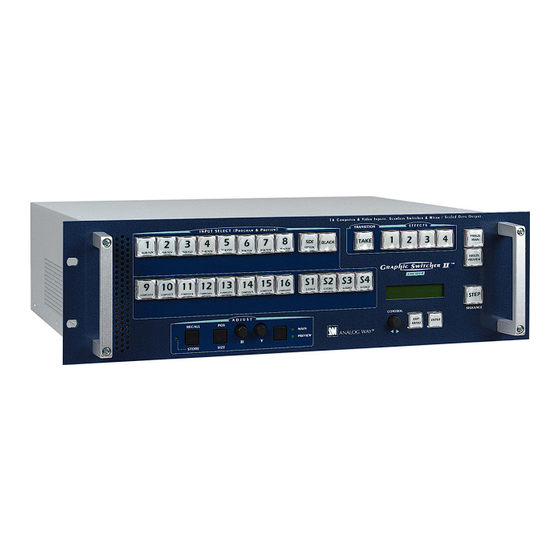
GRAPHIC SWITCHER II™ Chapter 3 : TECHNICAL DESCRIPTION 3-1. FRONT PANEL INPUT SELECT (PROGRAM & PREVIEW) 1 to 8 : 8 RGB/YUV input selection keys. 9 to 16 : 8 Composite Video input selection keys. S1 to S4 : 4 S.VIDEO (Y/C) input selection keys. SDI : Optional SDI input selection key. -
Page 8: Rear Panel
Chapter 3 : TECHNICAL DESCRIPTION (continued) GRAPHIC SWITCHER II™ 3-2. REAR PANEL POWER CONNECTOR: Standard IEC input connector (100-240 VAC, 50-60Hz automatic). O / I : Power switch (O = OFF, I = ON) RGB / YUV INPUTS 1 to 8 : 8 x RGB/YUV inputs on 3, 4, or 5 BNC connectors. -
Page 9: Chapter 4 : Starting
GRAPHIC SWITCHER II™ Chapter 4 : STARTING 4-1. CONNECTIONS Turn OFF all of your equipment before connecting. Connect your computers (PC, MAC, workstation), your component and RGBS video sources to the inputs (1 to 8) of the GSW2811R. Connect your COMPOSITE sources to the inputs (9 to 16) and/or your S.VIDEO sources to the inputs (S1 to S4). Connect your MAIN display device (data projector, plasma screen...) to the "MAIN"... - Page 10 Chapter 4 : STARTING (continued) GRAPHIC SWITCHER II™ 4-2. RGB/YUV INPUTS (1 to 8) The RGB/YUV INPUTS can accept both COMPUTER sources (RGBHV, RGBS, and RGsB (SOG) signals), standard TV/VIDEO sources (YUV(Component), RGBS (TTL), RGsB (SOG), and RGBS (analog) signals), and HDTV sources (720p &...
- Page 11 GRAPHIC SWITCHER II™ Chapter 4 : STARTING (continued) 4-3. COMPOSITE INPUTS (9 to 16) & S.VIDEO INPUTS (S1 to S4): The Composite Video signal, usually called COMPOSITE or VIDEO, is available on most video equipment (VCR, DVD, CAMCORDER…), but is also the lowest in picture quality. The video standard of this signal can be NTSC, PAL or SECAM.
-
Page 12: Chapter 5 : Operating Mode
GRAPHIC SWITCHER II™ Chapter 5 : OPERATING MODE 5-1. SETTINGS ™ We recommend resetting the GRAPHIC SWITCHER II to all of its default values, with the LCD screen (control menu > default value > yes) before proceeding. Then switch OFF and ON the device. Select the type of signal connected to the RGB/YUV inputs (input menu >... -
Page 13: Image Adjustments
GRAPHIC SWITCHER II™ Chapter 5 : OPERATING MODE (continued) 5-3. IMAGE ADJUSTMENTS ™ For each input source connected to the GRAPHIC SWITCHER II , make the following adjustments: Select the source you want to adjust. NOTE: To adjust your source on your PREVIEW monitor : you just have to press on the corresponding INPUT SELECT key. - Page 14 Chapter 5 : OPERATING MODE (continued) GRAPHIC SWITCHER II™ 5-6. EXAMPLES OF TRANSITIONS & EFFECTS WIPE TRANSITION: • Assign a WIPE to one of the EFFECTS keys: Press one EFFECTS key, select a WIPE (for example: hor wipe > left to right) then select the duration. •...
- Page 15 GRAPHIC SWITCHER II™ Chapter 5 : OPERATING MODE (continued) 5-6. EXAMPLES OF TRANSITIONS & EFFECTS (continued) PIP EFFECT: The PIP effect allows to insert an image into another one. • Assign the PIP effect to one of the EFFECTS keys: Press one EFFECTS key, select PIP, then make all the needed adjustments (duration, size, position...).
-
Page 16: Chapter 6 : Lcd Screen Description
GRAPHIC SWITCHER II™ Chapter 6 : LCD SCREEN DESCRIPTION 6-1. INTRODUCTION The LCD screen is composed of 2 modes: the STATUS MODE and the CONTROL MODE. • The STATUS MODE indicates the input and the output status of the GRAPHIC SWITCHER II ™... -
Page 17: Control Mode
GRAPHIC SWITCHER II™ Chapter 6 : LCD SCREEN DESCRIPTION (continued) 6-4. CONTROL MODE The menus of the CONTROL MODE are configured as follow : 1 input menu 1 input status main = xx The LCD displays prev = xx the video status 2 RGB/YUV inputs 1 SDTV YUV 1 RGB/YUV 1... - Page 18 Chapter 6 : LCD SCREEN DESCRIPTION (continued) GRAPHIC SWITCHER II™ 6-4. CONTROL MODE (continued) 4 effects menu 1 effect 1 key 1 cut 2 effect 2 key 2 fading 1s 3s 5s custom effect duration 3 effect 3 key ======= xxs 3 title 4 effect 4 key 4 shadow title...
-
Page 19: Chapter 7 : Lcd Functions Description
GRAPHIC SWITCHER II™ Chapter 7 : LCD FUNCTIONS DESCRIPTION 1 [INPUT MENU] + ENTER. 1-1[Input Status] + ENTER. Select [MAIN = x] or [PREV = x] with + ENTER. • [MAIN = x] = Number of the selected input. • [SYNC = xxxx] = Sync. type: [H+V+] = Separate H &... - Page 20 Chapter 7 : LCD FUNCTIONS DESCRIPTION (continued) GRAPHIC SWITCHER II™ 2 [OUTPUT MENU] + ENTER. 2-1[output format] + ENTER. Select one of the following output format with + ENTER. • If [output rate] = [internal rate], the LCD window displays the following formats : •...
- Page 21 GRAPHIC SWITCHER II™ Chapter 7 : LCD FUNCTIONS DESCRIPTION (continued) 2-5[type of screen] + ENTER. Select an item with + ENTER. • [screen 4/3] = if your image is displayed on a 4/3 wall mounted projection screen shape. • [screen 16/9] = if your image is displayed on a 16/9 wall mounted projection screen shape. 2-6[tally] + ENTER.
- Page 22 Chapter 7 : LCD FUNCTIONS DESCRIPTION (continued) GRAPHIC SWITCHER II™ 3 [IMAGE MENU] + ENTER. NOTE: The IMAGE adjustments act on the selected and/or the pre-selected input. Select [MAIN] to adjust the image displayed on the MAIN output and select [PREV] to adjust the image displayed on the PREVIEW output. •...
- Page 23 GRAPHIC SWITCHER II™ Chapter 7 : LCD FUNCTIONS DESCRIPTION (continued) 3-5[color] + ENTER Adjust the color with + ENTER. 3-6[hue] + ENTER. + ENTER. Adjust the tint of the picture (NTSC video sources only) with 3-7[image process] + ENTER. , and validate with ENTER. Select a level of process with 3-8[pos status] + ENTER.
- Page 24 Chapter 7 : LCD FUNCTIONS DESCRIPTION (continued) GRAPHIC SWITCHER II™ 4-x-5 [hor. wipe] = allows to switch the pre-selected input onto the MAIN output with a horizontal wipe effect. First select an horizontal wipe effect with + ENTER between: • [left to right] •...
- Page 25 GRAPHIC SWITCHER II™ Chapter 7 : LCD FUNCTIONS DESCRIPTION (continued) 4-x-8 [PIP] = allows to display a picture into another picture. The PREVIEW image is reduced and displayed onto the MAIN image. Select the [duration] of the transition , and validate with ENTER. •...
- Page 26 Chapter 7 : LCD FUNCTIONS DESCRIPTION (continued) GRAPHIC SWITCHER II™ 4-6[sequence mode] + ENTER. This mode allows programming a sequence of transition. The sequence can also be activated at any time during the show, and controlled step by step (one step = pre-selection + transition) by one key only: the STEP key. This function allows to simplify the use of the device during a show.
- Page 27 GRAPHIC SWITCHER II™ Chapter 7 : LCD FUNCTIONS DESCRIPTION (continued) 5 [CONTROL MENU] 5-1[languages] 5-2[key locking] + ENTER. Select which locking function you need with + ENTER. • [input] = Lock or unlock the input keys. • [adjust] = Lock or unlock the adjust functions. •...
-
Page 28: Chapter 8 : Updating The Graphic Switcher Ii
Switch OFF the GRAPHIC SWITCHER II (REAR PANEL SWITCH = O). 8-2. UPDATE INSTRUCTIONS: Open the file "Analog way GSW2811R updater" (in start/Program/ANALOG WAY/GSW2811R). Click on "START" on the SOFTWARE. ™ Press the ENTER button of the GRAPHIC SWITCHER II (FRONT PANEL), and SWITCH it ON simultaneously (REAR PANEL SWITCH = I ). -
Page 29: Chapter 9 : Control Software
GRAPHIC SWITCHER II™ Chapter 9 : CONTROL SOFTWARE 9-1. CONNECTION • CONNECTING THE RS-232 ™ Connect the serial port of your controlling device to the REMOTE RS-232 connector of the GRAPHIC SWITCHER II with a straight cable (DB9 pins female / DB9 pins male). •... -
Page 30: Software Set Up
Chapter 9 : CONTROL SOFTWARE (continued) GRAPHIC SWITCHER II™ 9-3. SOFTWARE SET UP Select the Serial port in the Control menu. ™ The GRAPHIC SWITCHER II is now connected to the computer. In the Input menu: - Select the type of signal connected to the RGB / YUV inputs (RGB/YUV section). - Select the COMPOSITE &... - Page 31 GRAPHIC SWITCHER II™ Chapter 9 : CONTROL SOFTWARE (continued) 9-3. SOFTWARE SET UP (continued) In the Output menu, select the Output rate, the Output format, the Output Sync and the TALLY outputs. Image menus (MAIN & PREVIEW): • If a video source is selected the image menu display the following parameters: - Adjust the position and the size of the image.
- Page 32 Chapter 9 : CONTROL SOFTWARE (continued) GRAPHIC SWITCHER II™ 9-3. SOFTWARE SET UP (continued) Image menus (continued): • If a computer source is selected the image menu display the following parameters: Effects menu: This menu allows to store effects in the Effects Keys. - Select an Effect Key (1, 2, 3, or 4).
- Page 33 GRAPHIC SWITCHER II™ Chapter 9 : CONTROL SOFTWARE (continued) 9-3. SOFTWARE SET UP (continued) Sequence menu: This mode allows programming a sequence of transition. The sequence can also be activated at any time during the show, and controlled step by step (one step = pre-selection + transition) by one key only: the STEP key. •...
-
Page 34: Chapter 10 : Rs-232 Programmer's Guide
GRAPHIC SWITCHER II™ Chapter 10 : RS-232 PROGRAMMER'S GUIDE 10-1. INTRODUCTION If you need to use your own Control Software from a PC, or WORKSTATION with an RS-232 port, the GRAPHIC ™ SWITCHER II allows communicating through an ASCII code protocol. ™... - Page 35 GRAPHIC SWITCHER II™ Chapter 10 : RS-232 PROGRAMMER'S GUIDE (continued) 10-4. COMMANDS AND RESPONSES TABLE The following table resumes all of the commands that are recognized as valid and the responses that will be returned to the control device. ASCII RESPONSE COMMAND TYPE...
- Page 36 Chapter 10 : RS-232 PROGRAMMER'S GUIDE (continued) GRAPHIC SWITCHER II™ 10-4. COMMANDS AND RESPONSES TABLE (continued) ASCII RESPONSE COMMAND TYPE VALUE COMMAND DESCRIPTION MIN MAX DESCRIPTION IMAGE COMMANDS Underscan / overscan (MAIN) Rd/Wr 0 = underscan 1 = overscan Underscan / overscan (PREVIEW) Rd/Wr 0 = underscan 1 = overscan...
- Page 37 GRAPHIC SWITCHER II™ Chapter 10 : RS-232 PROGRAMMER'S GUIDE (continued) 10-4. COMMANDS AND RESPONSES TABLE (continued) ASCII COMMAND VALUE COMMAND RESPONSE TYPE MIN MAX DESCRIPTION DESCRIPTION STATUS COMMANDS UNIT Measures unity in kHz. 65535 Horizontal period of input signal (M) 65535 Please see value description (next section).
- Page 38 Chapter 10 : RS-232 PROGRAMMER'S GUIDE (continued) GRAPHIC SWITCHER II™ 10-4. COMMANDS AND RESPONSES TABLE (continued) ASCII COMMAND VALUE COMMAND RESPONSE TYPE MIN MAX DESCRIPTION DESCRIPTION SEQUENCE MODE COMMANDS SEQS Function of the sequence mode. Rd/Wr Please see value description (next section). SEQV Validation of the selected function.
- Page 39 GRAPHIC SWITCHER II™ Chapter 10 : RS-232 PROGRAMMER'S GUIDE (continued) 10-5.VALUES DESCRIPTION TABLE (continued) ASCII COMMAND RESPONSE VALUE DESCRIPTION COMMAND DESCRIPTION Effect selection. 00 = CUT. 01 = FADING: automatic from 0.5 to 25 seconds or T-BAR. 02 = TITLE: automatic from 0.5 to 25 seconds or T-BAR. 03 = TITLE: holding.
- Page 40 Chapter 10 : RS-232 PROGRAMMER'S GUIDE (continued) GRAPHIC SWITCHER II™ 10-5.VALUES DESCRIPTION TABLE (continued) ASCII COMMAND RESPONSE VALUE DESCRIPTION COMMAND DESCRIPTION Frame frequency (in Hz) = (Line frequency in Hz) ÷ (ifd This command allows to calculate the input frame frequency in Hz (PREV). VALUE).
-
Page 41: Chapter 11 : Technical Specifications
GRAPHIC SWITCHER II™ Chapter 11 : TECHNICAL SPECIFICATIONS RGB/YUV INPUTS • COMPUTER FORMATS (PC, MAC , Workstation). Hardware Compatibility: Line frequency : From 31.5 kHz to 130 kHz. Resolutions : From 640 x 480 to 1600 x 1280. Sync : Separate H & V, COMP, SOG. Levels: R, G, B = 3 x 0.7 Vp/p. -
Page 42: Main & Preview Outputs
Chapter 11 : TECHNICAL SPECIFICATIONS (continued) GRAPHIC SWITCHER II™ SDI INPUT (Optional input on BNC connector). Signal: Component (4:2:2) serial digital input conforming to SMPTE-259M. Data rate: 270 Mbps. MAIN & PREVIEW OUTPUTS • MAIN (on BNC & HD15 female connectors) Levels: R, G, B = 3 x 0.7 Vp/p. - Page 43 GRAPHIC SWITCHER II™ Chapter 11 : TECHNICAL SPECIFICATIONS (continued) OPTIONAL VIDEO OUTPUT (continued) • Y DR DB (R-Y / Y / B-Y) COMPONENT (on DB9 connector). 15.625 kHz / 50 Hz ..15.735 kHz / 60 Hz (625L ..525L). Levels: Y = 1 Vp/p (0.7 V luma + 0.3 V sync).
-
Page 45: Chapitre 1 : Introduction
GRAPHIC SWITCHER II™ ™ GRAPHIC SWITCHER II (GSW2811R) Chapitre 1 : INTRODUCTION 1-1. MATERIEL FOURNI • 1 GRAPHIC SWITCHER II ™ (GSW2811R). • 1 cordon secteur. • 1 manuel utilisateur. • 1 disquette 3.5" (Logiciel de contrôle RS-232). Fourni avec l'option OPT-GSW2-VO : •... -
Page 46: Chapitre 2 : Installation
GRAPHIC SWITCHER II™ Chapitre 2 : INSTALLATION IMPORTANT: Merci de prendre connaissance des instructions de sécurité (page 3) avant l'installation du GRAPHIC ™ SWITCHER II • Montage sur table ™ Le GRAPHIC SWITCHER II est directement utilisable sur table. Il est équipé de pied en caoutchouc. -
Page 47: Chapitre 3 : Description Technique
GRAPHIC SWITCHER II™ Chapitre 3 : DESCRIPTION TECHNIQUE 3-1. FACE AVANT INPUT SELECT (PROGRAM & PREVIEW) 1 à 8 : 8 touches de sélection des entrées RGB/YUV. 9 à 16 : 8 touches de sélection des entrées Composite video. S1 à S4 : 4 touches de sélection des entrées S.VIDEO (Y/C). -
Page 48: Chapitre 3 : Description Technique (Suite)
Chapitre 3 : DESCRIPTION TECHNIQUE (suite) GRAPHIC SWITCHER II™ 3-2. FACE ARRIÈRE ENTRÉE SECTEUR: Connecteur d'entrée standard CEI (100-240 VAC, 50-60Hz automatique). O / I : Interrupteur d'alimentation générale ( O = OFF, I = ON). ENTREES RGB / YUV 1 à... -
Page 49: Chapitre 4 : Mise En Service
GRAPHIC SWITCHER II™ Chapitre 4 : MISE EN SERVICE 4-1. RACCORDEMENTS Eteignez tous les appareils avant d'effectuer les raccordements. Raccordez vos ordinateurs (PC, MAC, station de travail), vos sources vidéo RGBS et YUV aux entrées (1 à 8) du GSW2811R. Raccordez vos sources COMPOSITE aux entrées (9 à... - Page 50 Chapitre 4 : MISE EN SERVICE (suite) GRAPHIC SWITCHER II™ 4-2. ENTRÉES RGB/YUV (1 à 8) Les entrées RGB/YUV peuvent accepter à la fois les sources INFORMATIQUE (signaux RGBHV, RGBS, et RGsB (SOG)), les sources VIDEO standard (signaux YUV(Component), RGBS (TTL), RGsB (SOG), et RGBS (analog)), et les sources au format HDTV (720p &...
- Page 51 GRAPHIC SWITCHER II™ Chapitre 4 : MISE EN SERVICE (suite) 4-3. ENTRÉES COMPOSITE (9 à 16) et ENTRÉE S.VIDEO (S1 à S4) : Le signal Vidéo Composite, aussi appelé COMPOSITE ou VIDEO, est disponible sur la plupart des appareils vidéo (Magnétoscope , DVD, Caméra…), mais c’est aussi celui qui à...
-
Page 52: Chapitre 5 : Mode Opératoire
GRAPHIC SWITCHER II™ Chapitre 5 : MODE OPÉRATOIRE 5-1. RÉGLAGES ™ Nous conseillons de remettre tous les réglages par défauts du GRAPHIC SWITCHER II , avec la fonction "DEFAULT VALUE" de l'écran LCD (control menu > default value > yes). Ensuite éteignez puis rallumez l'appareil. -
Page 53: Chapitre 5 : Mode Opératoire (Suite)
GRAPHIC SWITCHER II™ Chapitre 5 : MODE OPÉRATOIRE (suite) 5-3. RÉGLAGES D'IMAGE ™ Pour toutes les sources raccordées au GRAPHIC SWITCHER II , effectuez les réglages suivants : Sélectionnez la source que vous voulez régler. NOTE: Pour régler votre source avec votre moniteur de prévisualisation : appuyez simplement sur la touche correspondante (la touche clignote et la source s'affiche sur le moniteur de prévisualisation). - Page 54 Chapitre 5 : MODE OPÉRATOIRE (suite) GRAPHIC SWITCHER II™ 5-6. EXEMPLES DE TRANSITIONS ET D'EFFETS TRANSITION PAR VOLET (WIPE): • Attribuez un WIPE à l'une des touches EFFECTS: Appuyez sur une touche EFFECTS, sélectionnez un WIPE (par exemple: hor wipe > left to right) puis sélectionnez une durée. •...
- Page 55 GRAPHIC SWITCHER II™ Chapitre 5 : MODE OPÉRATOIRE (suite) 5-6. EXEMPLES DE TRANSITIONS ET D'EFFETS (suite) EFFET PIP: L'effet PIP permet d'incruster une image dans une autre. • Attribuez l'effet PIP à l'une des touches EFFECTS: Appuyez sur une touche EFFECTS, sélectionnez PIP, puis effectuez tous les réglages nécessaire (durée, taille, position...).
-
Page 56: Chapitre 6 : Description De L'écran Lcd
GRAPHIC SWITCHER II™ Chapitre 6 : DESCRIPTION DE L'ÉCRAN LCD 6-1. INTRODUCTION L'écran LCD est composé de 2 modes : le mode ÉTAT et le mode RÉGLAGE. • Le MODE ÉTAT indique l'état des entrées sélectionnées et l'état des sorties du GRAPHIC SWITCHER II ™... -
Page 57: Mode Réglage
GRAPHIC SWITCHER II™ Chapitre 6 : DESCRIPTION DE L'ÉCRAN LCD (suite) 6-4. MODE RÉGLAGE Les menus du MODE RÉGLAGE sont configurés comme ci-dessous: 1 input menu 1 input status main = xx The LCD displays prev = xx the video status 2 RGB/YUV inputs 1 RGB/YUV 1 1 SDTV YUV... -
Page 58: Mode Réglage(Suite)
Chapitre 6 : DESCRIPTION DE L'ÉCRAN LCD (suite) GRAPHIC SWITCHER II™ 6-4. MODE RÉGLAGE(suite) 4 effects menu 1 effect 1 key 1 cut 2 effect 2 key 2 fading 1s 3s 5s custom effect duration 3 effect 3 key ======= xxs 3 title 4 effect 4 key 4 shadow title... -
Page 59: Chapitre 7 : Description Des Fonctions De L'écran Lcd
GRAPHIC SWITCHER II™ Chapitre 7 : DESCRIPTION DES FONCTIONS DE L'ÉCRAN LCD 1 [INPUT MENU] + ENTER. 1-1[Input Status] + ENTER. Sélectionnez [MAIN = x] ou [PREV = x] avec + ENTER. • [MAIN = x] = Numéro de l'entrée sélectionnée. •... -
Page 60: Chapitre 7 : Description Des Fonctions De L'écran Lcd (Suite)
Chapitre 7 : DESCRIPTION DES FONCTIONS DE L'ÉCRAN LCD (suite) GRAPHIC SWITCHER II™ 2 [OUTPUT MENU] + ENTER. 2-1[output format] + ENTER. Sélectionnez un des formats de sortie suivants avec + ENTER. • Si [output rate] = [internal rate], l'écran LCD affiche les formats suivants : •... - Page 61 GRAPHIC SWITCHER II™ Chapitre 7 : DESCRIPTION DES FONCTIONS DE L'ÉCRAN LCD (suite) 2-5[type of screen] + ENTER. Sélectionnez une fonction avec + ENTER. • [screen 4/3] = si votre image est affichée sur une toile d'écran 4/3. • [screen 16/9] = si votre image est affichée sur une toile d'écran 16/9. 2-6[tally] + ENTER.
- Page 62 Chapitre 7 : DESCRIPTION DES FONCTIONS DE L'ÉCRAN LCD (suite) GRAPHIC SWITCHER II™ 3 [IMAGE MENU] + ENTER. NOTE : Les réglages d'image agissent sur l'entrée sélectionnée et/ou sur l'entrée présélectionnée. Sélectionnez [MAIN] pour effectuer les réglages à l'aide de l'afficheur principal, et [PREV] pour effectuer les réglages à l'aide du moniteur de contrôle.
- Page 63 GRAPHIC SWITCHER II™ Chapitre 7 : DESCRIPTION DES FONCTIONS DE L'ÉCRAN LCD (suite) 3-5[color] + ENTER. Réglez la couleur avec + ENTER. 3-6[hue] + ENTER. + ENTER. Réglez le HUE (video NTSC seulement) avec 3-7[image process] + ENTER. et validez avec ENTER. Sélectionnez un niveau avec 3-8[pos status] + ENTER.
- Page 64 Chapitre 7 : DESCRIPTION DES FONCTIONS DE L'ÉCRAN LCD (suite) GRAPHIC SWITCHER II™ 4-x-5 [hor wipe] = permet de commuter l'entrée présélectionnée sur la sortie MAIN avec un volet horizontal. Sélectionnez d'abord un type d'effet avec + ENTER entre: • [left to right] •...
- Page 65 GRAPHIC SWITCHER II™ Chapitre 7 : DESCRIPTION DES FONCTIONS DE L'ÉCRAN LCD (suite) 4-x-8 [PIP] = permet d'afficher une image dans une autre. L'image PREVIEW est réduite puis affichée dans l'image MAIN. Sélectionnez la durée de la transition [duration], et validez avec ENTER. •...
- Page 66 Chapitre 7 : DESCRIPTION DES FONCTIONS DE L'ÉCRAN LCD (suite) GRAPHIC SWITCHER II™ 4-6[sequence mode] + ENTER. Ce mode permet de programmer une séquence de transition. Cette séquence peut être activée à tout instant durant une prestation, et être contrôlée étape par étape (une étape = présélection + transition) par une touche seulement: la touche STEP.
- Page 67 GRAPHIC SWITCHER II™ Chapitre 7 : DESCRIPTION DES FONCTIONS DE L'ÉCRAN LCD (suite) 5 [CONTROL MENU] 5-1[languages] 5-2[key locking] + ENTER. + ENTER. Sélectionnez la fonction de verrouillage dont vous avez besoin avec • [input] = Verrouille ou déverrouille les touches de sélections. •...
-
Page 68: Chapitre 8 : Mise A Jour Du Graphic Switcher Ii
Eteignez votre GRAPHIC SWITCHER II (INTERRUPTEUR DE LA FACE ARRIÈRE = O). 8-2. INSTRUCTIONS DE MISE A JOUR Ouvrez le fichier "Analog way GSW2811R updater". (dans Démarrer/Programmes/ANALOG WAY/GSW2811R). Cliquez sur le bouton "START" du logiciel. ™ Maintenez enfoncé le bouton ENTER du GRAPHIC SWITCHER II (FACE AVANT), puis mettez le GRAPHIC ™... -
Page 69: Chapitre 9 : Utilisation Du Logiciel
GRAPHIC SWITCHER II™ Chapitre 9 : UTILISATION DU LOGICIEL 9-1. RACCORDEMENTS • RACCORDEMENT DE LA RS-232 Reliez le port série de votre appareil de contrôle (ordinateur) au connecteur (DB 9 F) REMOTE RS-232 du GRAPHIC ™ SWITCHER II avec un câble droit (DB 9 Femelle / DB 9 Mâle). •... -
Page 70: Chapitre 9 : Utilisation Du Logiciel (Suite)
Chapitre 9 : UTILISATION DU LOGICIEL (suite) GRAPHIC SWITCHER II™ 9-3. ÉCRANS DE CONTRÔLE Sélectionnez le port série (Serial port) dans le menu Control. ™ The GRAPHIC SWITCHER II est maintenant connecté à l'ordinateur. Dans le menu Input: - Sélectionnez le type de signal raccordé aux entrées RGB / YUV (onglet RGB/YUV). - Sélectionnez le mode COMPOSITE &... - Page 71 GRAPHIC SWITCHER II™ Chapitre 9 : UTILISATION DU LOGICIEL (suite) 9-3. ÉCRANS DE CONTRÔLE (suite) Dans le menu Output, sélectionnez le mode de synchronisation (Output rate), le format de sortie (Output format), les synchro. de sortie (Output Sync), et les sorties TALLY. Menus Image (MAIN &...
-
Page 72: Écrans De Contrôle (Suite)
Chapitre 9 : UTILISATION DU LOGICIEL (suite) GRAPHIC SWITCHER II™ 9-3. ÉCRANS DE CONTRÔLE (suite) Menus Image (suite): • Si une source informatique est sélectionnée le menu image affiche les paramètres suivants: Menu Effects: ce menu permet de mémoriser des effets dans chacune des 4 touches d'effets (Effect Keys). - Sélectionnez une touche d'effet (Effect keys 1, 2, 3, ou 4). -
Page 73: Pour Programmer Une Séquence
GRAPHIC SWITCHER II™ Chapitre 9 : UTILISATION DU LOGICIEL (suite) 9-3. ÉCRANS DE CONTRÔLE (suite) Menu Sequence: ce mode permet de programmer une séquence de transition. Cette séquence peut être activée à tout instant durant une prestation, et être contrôlée étape par étape (une étape = présélection + transition) par une touche seulement: la touche STEP. -
Page 74: Chapitre 10 : Guide De Programmation Rs-232
GRAPHIC SWITCHER II™ Chapitre 10 : GUIDE DE PROGRAMMATION RS-232 10-1. INTRODUCTION Si vous souhaitez utiliser votre propre logiciel de contrôle à partir d'un PC ou d'une Station de travail équipé d'un port ™ RS-232, le GRAPHIC SWITCHER II permet de communiquer par simple émission / réception de caractère ASCII. ™... -
Page 75: Chapitre 10 : Guide De Programmation Rs-232 (Suite)
GRAPHIC SWITCHER II™ Chapitre 10 : GUIDE DE PROGRAMMATION RS-232 (suite) 10-4. TABLEAU DES COMMANDES ET RÉPONSES Le tableau suivant résume les commandes qui sont reconnues comme valable et les réponses qui seront retournées. COMMANDE RÉPONSE DESCRIPTION TYPE VALEUR ASCII DE LA COMMANDE MIN MAX DESCRIPTION... - Page 76 Chapitre 10 : GUIDE DE PROGRAMMATION RS-232 (suite) GRAPHIC SWITCHER II™ 10-4. TABLEAU DES COMMANDES ET RÉPONSES (suite) COMMANDE RÉPONSE DESCRIPTION TYPE VALEUR ASCII DE LA COMMANDE MIN MAX DESCRIPTION COMMANDES D'IMAGE Underscan / overscan (MAIN) Rd/Wr 0 = underscan 1 = overscan Underscan / overscan (PREVIEW) Rd/Wr...
- Page 77 GRAPHIC SWITCHER II™ Chapitre 10 : GUIDE DE PROGRAMMATION RS-232 (suite) 10-4. TABLEAU DES COMMANDES ET RÉPONSES (suite) COMMANDE RÉPONSE DESCRIPTION TYPE VALEUR ASCII DE LA COMMANDE MIN MAX DESCRIPTION COMMANDES D'ÉTATS UNIT Mesure l'unité en kHz. 65535 Fréquence ligne d'entrée (MAIN) 65535 Voir description des valeurs (section suivante).
- Page 78 Chapitre 10 : GUIDE DE PROGRAMMATION RS-232 (suite) GRAPHIC SWITCHER II™ 10-4. TABLEAU DES COMMANDES ET RÉPONSES (suite) COMMANDE RÉPONSE DESCRIPTION TYPE VALEUR ASCII DE LA COMMANDE MIN MAX DESCRIPTION COMMANDES DU MODE SEQUENCE SEQS Fonction du mode séquence. Rd/Wr Voir description des valeurs (section suivante).
-
Page 79: Description De La Valeur
GRAPHIC SWITCHER II™ Chapitre 10 : GUIDE DE PROGRAMMATION RS-232 (suite) 10-5. TABLEAU DE DESCRIPTION DES VALEURS (suite) COMMANDE REPONSE DESCRIPTION DE LA DESCRIPTION DE LA VALEUR ASCII COMMANDE Sélection des effets. 00 = CUT. 01 = FADING: automatique (de 0,5s à 25 secondes) ou contrôlé par un T-BAR. 02 = TITLE: automatique de (0,5s à... -
Page 80: Commande Reponse Description De La Commande Ascii
Chapitre 10 : GUIDE DE PROGRAMMATION RS-232 (suite) GRAPHIC SWITCHER II™ 10-5. TABLEAU DE DESCRIPTION DES VALEURS (suite) COMMANDE REPONSE DESCRIPTION DE LA COMMANDE DESCRIPTION DE LA VALEUR ASCII Cette commande permet de calculer la Fréquence trame (en Hz) = (Fréquence trame en Hz) ÷ (ifd VALUE) fréquence trame en Hz (PREV). -
Page 81: Chapitre 11 : Spécifications Techniques
GRAPHIC SWITCHER II™ Chapitre 11 : SPÉCIFICATIONS TECHNIQUES ENTRÉES RGB/YUV • FORMATS INFORMATIQUE (PC, MAC, Station de travail) Compatibilité matérielle: Fréquence ligne : De 31,5 kHz à 130 kHz. Résolutions : De 640 x 480 à 1600 x 1280. Synchro. : H et V séparées, Composite, Synchro. sur le vert. Niveaux: R, G, B = 3 x 0,7 Vc/c. -
Page 82: Chapitre 11 : Spécifications Techniques (Suite)
Chapitre 11 : SPÉCIFICATIONS TECHNIQUES (suite) GRAPHIC SWITCHER II™ ENTRÉE SDI (Entrée optionnelle sur 1 connecteur BNC) Signal: Entrée numérique Component (4:2:2) conformément à la norme SMPTE-259M. Débit: 270 Mbps. SORTIES MAIN ET PREVIEW • MAIN (sur connecteurs BNC et HD15 femelle). Niveaux: R, G, B = 3 x 0,7 Vc/c. -
Page 83: Environnement
GRAPHIC SWITCHER II™ Chapitre 11 : SPÉCIFICATIONS TECHNIQUES (suite) SORTIE VIDÉO OPTIONNELLE (suite) • Y DR DB (R-Y / Y / B-Y) COMPONENT (sur connecteur DB9) 15,625 kHz / 50 Hz ..15,735 kHz / 60 Hz (625L ..525L). Niveaux: Y = 1 Vc/c (0,7 V Luma + 0,3 V Synchro.). -
Page 84: Garantie
In case of any problem, get the serial number of the unit, a description of the problem, and then call your authorized dealer. GARANTIE Analog Way garantie le produit contre les défauts matériels et vices de fabrication, pour une période de 3 ans à partir de la date d'achat (retour en nos locaux).