Sommaire des Matières pour mad NR-367134-B
- Page 1 NR-367134-B, NR-367134-CM, NR-367144-CM, NR-367134-R, NR-367144-R Toyota Hilux NL Montage handleiding EN Fitting instructions DE Einbau Anleitung FR Guide d'installation VH3670713-05...
- Page 2 Inhoudsopgave 1. Voorwoord 2. Technische gegevens 3. Montage luchtveer montagebeugels en balgen 4. Montage NR-367134-B, Air Master Basic 5. Schema, Air Master Basic 6. Montage NR-367134-CM (LHD), NR-367144-CM (RHD), Air Master Comfort 7. Schema, Air Master Comfort 8. Montage NR-367134-R (LHD), NR-367144-R (RHD), Air Master Automatic 9.
- Page 3 • L'installation du kit de ressort à air auxiliaire doit être effectuée par un technicien qualifié. Les dommages causés par un montage incorrect ou des modifications du produit sont exclus de la garantie MAD. • Le kit d'air auxiliaire peut être commandé avec différents systèmes de commande. Les supports de fixa- tion et le soufflet pour ces différentes commandes sont identiques.
- Page 4 NR-367134-B, NR-367134-CM, NR-367144-CM, NR-367134-R, NR-367144-R https://mad-automotive.com/documents/VH3670713.pdf https://mad-automotive.com/documents/TU-026397.pdf https://mad-automotive.com/documents/9901.pdf...
- Page 5 NR-367134-B, NR-367134-CM, NR-367144-CM, NR-367134-R, NR-367144-R 2. Technical specifications Luchtdruk • De minimale luchtdruk bedraagt 0,5 bar. • De bedrijfsdruk ligt tussen de 1,0 - 3,0 bar. • De maximale geoorloofde luchtdruk bedraagt 7,0 bar. • De maximale luchtdruk is alleen voor de parkeerstand en tijdens het rangeren geoorloofd.
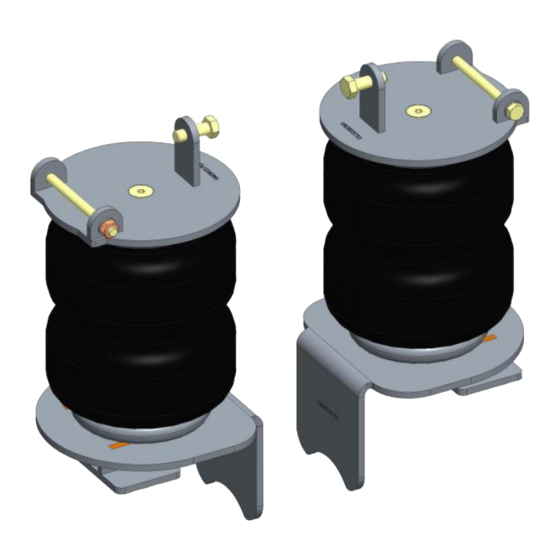
- Page 6 NR-367134-B, NR-367134-CM, NR-367144-CM, NR-367134-R, NR-367144-R Fitting the air suspension brackets and bellows Bill of material: Brackets and bellows Item Part nr Name Quantity VM3613713 Upper bracket VC13005 Bolt M8x110 M8 DIN125A M8 washer M8 DIN985 M8 lock nut M10X30 DIN933...
- Page 7 NR-367134-B, NR-367134-CM, NR-367144-CM, NR-367134-R, NR-367144-R Draai de vier moeren van de veerstroppen een stukje los. Doe dit niet aan beide kanten tegelijk. Loosen the four nuts of the U-bolts a little. Do not do this on both sides at once.
- Page 8 NR-367134-B, NR-367134-CM, NR-367144-CM, NR-367134-R, NR-367144-R Controleer of de onderbeugel goed gepositioneerd is. Voertuig iets laten zakken. Zet de veerstroppen vast met het voorgeschreven aanhaalmoment. Verify if the lower bracket is well positioned. Lower the car a little. Tighten the U-bolts to the specified torque.
- Page 9 NR-367134-B 4/5. Air Master Basic...
- Page 10 NR-367134-CM, NR-367144-CM 6. Montage Air Master Comfort Het bedieningspaneel kan op verschillende plekken worden gemonteerd. Als het paneel in de cabine van het voertuig gemonteerd wordt dan dient deze, in verband met richtlijn ECE-R 21, tussen of achter de laatste zitrij te worden geplaatst. Ook is het mogelijk om het bedieningspaneel in de laadruimte van het voertuig te plaatsen.
- Page 11 NR-367134-CM, NR-367144-CM Alleen Left Hand Drive: Bevestigingspunten compres- sorunit. Rechts in het motorruim. Plaats in het gat zon- der schroefdraad de meegeleverde blindklinkmoer met een blindklinkmoerentang. Only Left Hand Drive: Attachment points compressor unit. On the right side in the engine compartment. Place in the hole without thread the supplied blind rivet nut with a blind rivet nut pliers.
- Page 12 NR-367134-CM, NR-367144-CM Alleen Left Hand Drive: Monteer de Compressorsteun met compressor zoals aangegeven op de afbeelding. Gebruik meegeleverd montagemateriaal. Zie afbeelding bovenaan. Steun de rubber voet af op de carrosserie. Only Left Hand Drive: Mount the compressor with bracket as shown. Use the supplied mounting material. See image above.
- Page 13 NR-367134-CM, NR-367144-CM 7. Diagram Air Master Comfort Air line diagram Left air bellow Right air bellow Compressor Operation Pump left Pump right Deflate left Deflate right...
- Page 14 NR-367134-CM, NR-367144-CM Electrical Diagram (12 VDC) Relay ground Fuse 30 A (12 VDC) Wire 0.75 mm² ground Wire 1.5 mm² Compressor Sluit de luchtleidingen en elektra aan volgens schema. Let op dat de luchtleidingen en bedrading vrij liggen van scherpe delen. Monteer de compressor op een afgeschermde droge plaats. Connect the air lines and wire harness according the diagram.
- Page 15 NR-367134-CM, NR-367144-CM Bill of material Item Part nr Name Quantity VM70202 Operation panel VX70008 Manometer VE01003 Paddle switch VC20004 Line clamp Ø 6 mm VF01051 Fitting 1/8 for line 4-6 VF01052 Y-fitting Ø 6 mm VL02007 Line PU blue 4-6 65 cm VL02007 Line PU blue 4-6...
- Page 16 NR-367134-R, NR-367144-R 8. Air Master Automatic Front...
- Page 17 NR-367134-R, NR-367144-R Monteer de magneetsteun op de achteras. Gebruik hiervoor de originele bout van het kabel bescherm schild. Fit the magnet bracket on the rear axle. Use the original bolt from the cable protect shield. Montieren Sie den Magnethalterung an der Hinterach- se.
- Page 18 NR-367134-R, NR-367144-R Alleen Left Hand Drive: Bevestigingspunten compres- sorunit. Rechts in het motorruim. Plaats in het gat zon- der schroefdraad de meegeleverde blindklinkmoer met een blindklinkmoerentang. Only Left Hand Drive: Attachment points compressor unit. On the right side in the engine compartment. Place in the hole without thread the supplied blind rivet nut with a blind rivet nut pliers.
- Page 19 NR-367134-R, NR-367144-R Alleen Left Hand Drive: Monteer de Compressorsteun met compressor zoals aangegeven op de afbeelding. Gebruik meegeleverd montagemateriaal. Zie afbeelding bovenaan. Steun de rubber voet af op de carrosserie. Only Left Hand Drive: Mount the compressor with bracket as shown. Use the supplied mounting material. See image above.
- Page 20 NR-367134-R, NR-367144-R 9. Diagram and adjustment Air Master Automatic Sluit de luchtleidingen en elektra aan volgens schema. Let op dat de luchtleidingen en bedrading vrij liggen van scherpe delen. Connect the air lines and wire harness according the diagram. Make sure that the air lines and wiring are free from sharp edges.
- Page 21 NR-367134-R, NR-367144-R Stel het Air Master Automatic system af zodat de afstand tussen de sensor en de magneet ongeveer 30 -mm is. Plaats de magneet zodat deze net iets boven het midden van de sensor. Het is mogelijk om de rijhoogte aan te passen door de magneet over de steun te verplaatsen.
- Page 24 Wiltonstraat 53 3905 KW Veenendaal The Netherlands T +31 (0) 318 586 100 mad-automotive.com...


