PR electronics Preasy 4116 Mode D'emploi
Masquer les pouces
Voir aussi pour Preasy 4116:
- Manuel (55 pages) ,
- Mode d'emploi (38 pages) ,
- Guide rapide (14 pages)
Publicité
Les langues disponibles
Les langues disponibles
Liens rapides
Displays
Programmable displays with a wide se-
lection of inputs and outputs for display of temperature,
volume and weight, etc. Feature linearisation, scaling,
and difference measurement functions for programming
via PReset software.
Ex interfaces
Interfaces
for
analogue
signals as well as HART
®
signals between sensors / I/P
converters / frequency signals and control systems in Ex
zone 0, 1 & 2 and for some modules in zone 20, 21 & 22.
Isolation
Galvanic isolators for analogue and digital
signals as well as HART
signals. A wide product range
®
with both loop-powered and universal isolators featuring
linearisation, inversion, and scaling of output signals.
Temperature
A wide selection of transmitters for DIN
form B mounting and DIN rail modules with analogue
and digital bus communication ranging from application-
specific to universal transmitters.
Universal
PC or front programmable modules with
universal options for input, output and supply. This range
offers a number of advanced features such as process
calibration, linearisation and auto-diagnosis.
All manuals and user guides at all-guides.com
and
digital
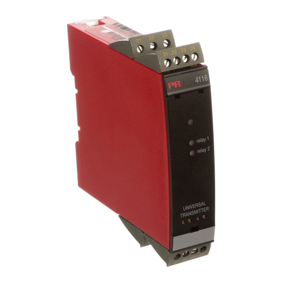
4 1 1 6
U n i v e r s a l
T r a n s m i t t e r
N o . 4 1 1 6 V 1 0 3 - I N ( 0 9 4 5 )
F r o m s e r . n o . 0 9 0 3 9 0 0 0 1
S I G N A L S T H E B E S T
Side 1
DK
Page 33
UK
Page 65
FR
Seite 97
DE
Publicité

Manuels Connexes pour PR electronics Preasy 4116


Sommaire des Matières pour PR electronics Preasy 4116
- Page 1 All manuals and user guides at all-guides.com Displays Programmable displays with a wide se- lection of inputs and outputs for display of temperature, volume and weight, etc. Feature linearisation, scaling, and difference measurement functions for programming via PReset software. Ex interfaces Interfaces analogue digital...
- Page 2 All manuals and user guides at all-guides.com Universal TransMiTTer Preasy 4116 indholdsforTegnelse Advarsel ................Signaturforklaring ............... Sikkerhedsregler ..............EF-overensstemmelseserklæring ........Når LED i front lyser rødt / display viser AO.ER ....Avancerede features............Anvendelse ................. Teknisk karakteristik ............PR 4501 display- / programmeringsfront......
- Page 3 Hvis der er tvivl om modulets rette håndtering, skal der rettes henvendelse til på stikforbindelsen til display- / programmeringsfronten PR den lokale forhandler eller alternativt direkte til Pr electronics a/s, lerbakken 4501. Modulet indeholder ingen DIP-switche eller jumpere. 10, 8410 rønde, danmark, tlf: +45 86 37 26 77.
- Page 4 I det omfang instruktionerne i denne manual ikke er nøje overholdt, vil kunden ikke kunne rette noget krav, som ellers måtte eksistere i henhold til den indgå- ede salgsaftale, mod PR electronics A/S. Rønde, 28. august 2009 Kim Rasmussen...
- Page 5 All manuals and user guides at all-guides.com afMonTering af sysTeM 4000 Universal TransMiTTer Preasy 4116 Husk først at demontere tilslutningsklemmerne med farlig spænding. • Indgang for RTD, TC, Ohm, potentiometer, mA og V billede 1: • 2-trådsforsyning > 16 V Modulet frigøres fra DIN-skinnen ved...
- Page 6 All manuals and user guides at all-guides.com Pr 4501 disPlay- / PrograMMeringsfronT aPPlikaTioner Indgangssignaler: Spæn- Potenti- Strøm ding RTD og lin.R ometer funktionalitet: Forbindelse, ledere Den enkle PReasy menustruktur og de forklarende hjælpe- tekster leder dig automatisk gennem opsætningen, og gør produktet meget enkelt at anvende.
- Page 7 All manuals and user guides at all-guides.com bestillingsnumre EMC-immunitetspåvirkning ......... < ±0,5% af span Udvidet EMC-immunitet: 4116 = Universal transmitter NAMUR NE 21, A-kriterium, gniststøj ....< ±1% af span 4501 = display- / programmeringsfront 5910 = CjC-klemme Hjælpespændinger: 2-trådsforsyning (klemme 44...43) ....25...16 VDC / 0...20 mA Ledningskvadrat (max.) .......
- Page 8 All manuals and user guides at all-guides.com TC-indgang: Følerfejlsdetektering ........0 / 3,5 / 23 mA / ingen NAMUR NE 43 Up- / Downscale ....23 mA / 3,5 mA Min. Max. Begrænsning af udgang: Type værdi værdi Standard på 4...20 og 20...4 mA signaler ....3,8...20,5 mA +0°C +1820°C IEC 60584-1...
- Page 9 All manuals and user guides at all-guides.com TilslUTninger Uden for område visning (IN.LO, IN.HI): Ved overskridelse af A/D-konverterens eller polynomiets gyldige område. Indgang Område Visning Grænse Forsyning: IN.LO < -25 mV 0...1 V / 0,2...1 V IN.HI > 1,2 V VOLT IN.LO <...
- Page 10 All manuals and user guides at all-guides.com blokdiagraM PrograMMering / beTjening af TrykknaPPer 2-trådstransmitter Strøm Dokumentation til rutediagram Spænding generelt: Poten tiome ter Når du skal konfigurere 4116, bliver du guidet igennem samtlige parametre og kan vælge netop de indstillinger, der passer til applikationen. Til hver menu findes en rullende hjælpetekst, som vises i displaylinie 3.
- Page 11 All manuals and user guides at all-guides.com signal- og følerfejlsinformation via displayfront 4501 Latch-funktionen kan vælges separat for hver relæudgang. Hvis opsætningen kopieres fra en enhed til en anden via 4501, skal latchen genindkodes. Følerfejl (se grænser i skema) vises i display med SE.BR (sensor break) eller SE.SH (sensor short).
- Page 12 All manuals and user guides at all-guides.com valg af units avancerede funktioner Enheden giver adgang til en række avancerede funktioner, der nås ved at svare Efter valg af indgangssignaltype kan man vælge, hvilke procesenheder der skal ”yes” til punktet ”adv.set”. vises i displayet (se skema).
- Page 13 All manuals and user guides at all-guides.com rUTediagraM Power up Hurtig setpunktsindstilling 50.0 Hvis ingen taster har været aktiveret i 1 minut, returnerer displayet til nor- og test af relæer RELAY1 maltilstanden 1.0 uden at gemme eventuelle konfigurationsændringer. 1 Forøgelse af setpunkt Txt 57 1 Forøgelse af værdi / vælg næste parameter 2 Formindskelse af setpunkt...
- Page 14 All manuals and user guides at all-guides.com S20-4 20-4 20-0 SETP S4-20 HOLD WIND HOLD 4-20 CLOS CLOS 23mA 0-20 OPEN 3600 3600 N.O. 9999 INCR 250.0 OPEN 3600 3600 VOLT 0/3.5mA 4172 4172 NONE 0000 0000 N.C. -1999 DECR NONE 0000 0000...
- Page 15 All manuals and user guides at all-guides.com rUTediagraM rUTediagraM Manual deaktivering af latch Avancerede indstillinger (ADV.SET) 2.0 I undermenuen simulering (SIM) skal 3 DISP trykkes for at returnere til normaltilstand 1.0 SAVE PASS LOAD LANG SAVE SETUP MEMORY Txt 43 Txt 44 A.OUT Til setup menu...
- Page 16 All manuals and user guides at all-guides.com rUllende hjÆlPeTeksTer i disPlaylinie 3 [01] Angiv korrekt password [20] Vælg kontakt normalt åben [49] Kalibrer indgang lav til procesværdi? [02] Gå til avanceret opsætningsmenu? Vælg kontakt normalt lukket [50] Kalibrer indgang høj til procesværdi? [03] Vælg temperaturindgang [21]...
- Page 17 All manuals and user guides at all-guides.com grafisk afbildning af latchfunktion setpunkt grafisk afbildning af latchfunktionen vindue Indgangs- ON-forsinkelse signal OFF-forsinkelse Setpunkt (stigende) Hysterese Sluttet Relækontakt Relæ latched (N.O.) Brudt Frigørelse ikke mulig (setpunkt stadig overskredet) Frigørelse ikke mulig (setpunkt-hysterese stadig overskredet) Frigørelse ikke mulig (OFF-forsinkelse stadig overskredet) Frigørelse mulig (manuel deaktivering)
- Page 18 All manuals and user guides at all-guides.com Universal TransMiTTer grafisk afbildning af relæfunktionen setpunkt Relæenheder Relæenheder Preasy 4116 ConTenTs Hysterese = 10 Setpunkt = 50 Setpunkt = 50 Warning ................34 Hysterese = 10 Symbol identification ............35 Safety instructions .............. 35 Off N.O.
- Page 19 Should there be any doubt as to the correct handling of the device, please Do not open the front plate of the device as this will cause contact your local distributor or, alternatively, Pr electronics a/s, lerbakken damage to the connector for the display / programming front 10, dk-8410 rønde, denmark, tel: +45 86 37 26 77.
- Page 20 To the extent that the instructions in this manual are not strictly observed, the customer cannot advance a demand against PR electronics A/S that would otherwise exist according to the concluded sales agreement. Rønde, 28 August 2009 Kim Rasmussen Manufacturer’s signature...
- Page 21 All manuals and user guides at all-guides.com hoW To disManTle sysTeM 4000 Universal TransMiTTer Preasy 4116 First, remember to demount the connectors with hazardous voltages. • Input for RTD, TC, Ohm, potentiometer, mA and V Picture 1: • 2-wire supply > 16 V Detach the device from the DIN rail •...
- Page 22 All manuals and user guides at all-guides.com Pr 4501 disPlay / PrograMMing fronT aPPliCaTions Input signals: Volt - Potenti- Current RTD and lin.R ometer functionality Connect., wires The simple and easily understandable PReasy menu structure and the explanatory help texts guide you effortless ly and automatically through the configuration steps, thus making the product very easy to use.
- Page 23 All manuals and user guides at all-guides.com order codes EMC immunity influence ........< ±0.5% of span Extended EMC immunity: 4116 = Universal transmitter NAMUR NE 21, A criterion, burst ....... < ±1% of span 4501 = display / programming front 5910 = CjC connector Auxiliary supplies: 2-wire supply (terminal 44...43) ....
- Page 24 All manuals and user guides at all-guides.com TC input: Sensor error detection ........ 0 / 3.5 / 23 mA / none NAMUR NE 43 Upscale / Downscale ..23 mA / 3.5 mA Min. Max. Output limitation: Type value value Standard on 4...20 and 20...4 mA signals ....
- Page 25 All manuals and user guides at all-guides.com ConneCTions Outside range readout (IN.LO, IN.HI): If the valid range of the A/D converter or the polynomial is exceeded Input Range Readout Limit Supply: IN.LO < -25 mV 0...1 V / 0.2...1 V IN.HI >...
- Page 26 All manuals and user guides at all-guides.com bloCk diagraM ConfigUraTion / oPeraTing The fUnCTion keys 2-wire transmitter Current Documentation for routing diagram. Voltage in general: Potentiome ter When configuring the 4116, you will be guided through all parameters and you can choose the settings which fit the application.
- Page 27 All manuals and user guides at all-guides.com signal and sensor error info via display front 4501 is deactivated manually. The latch function can be applied when the relay function setpoint or window is selected. Sensor error (see limits in the table) is displayed as SE.BR (sensor break) or The latch function can be selected separately for each relay output.
- Page 28 All manuals and user guides at all-guides.com advanced functions selection of units The device gives access to a number of advanced functions which can be After choosing the input signal type you can choose which process units should reached by answering “Yes” to the point “adv.set”. be displayed in text line 2 (see table).
- Page 29 All manuals and user guides at all-guides.com roUTing diagraM Power up Fast setpoint adjustment If no key is activated for 1 minute, the display will return to the default 50.0 and relay test state 1.0 without saving configuration changes. RELAY1 1 Increase setpoint Txt 57 1 Increase value / choose next parameter...
- Page 30 All manuals and user guides at all-guides.com S20-4 20-4 SETP 20-0 HOLD WIND HOLD S4-20 CLOS CLOS 23mA 4-20 OPEN 3600 3600 N.O. 9999 INCR 250.0 OPEN 3600 3600 VOLT 0/3.5mA 4172 4172 0-20 NONE 0000 0000 N.C. -1999 DECR NONE 0000 0000...
- Page 31 All manuals and user guides at all-guides.com roUTing diagraM roUTing diagraM Manual deactivation of the latch function Advanced settings (ADV.SET) 2.0 In the submenu simulation (SIM) you must DISP press 3 to return to the default state 1.0. PASS SAVE LANG LOAD SAVE...
- Page 32 All manuals and user guides at all-guides.com sCrolling helP TexT in disPlay line 3 [01] Set correct password [20] Select Normally Closed contact [49] Calibrate input low to process value? [02] Enter advanced setup menu? Select Normally Open contact [50] Calibrate input high to process value? [03] Select temperature input...
- Page 33 All manuals and user guides at all-guides.com graphic depiction of latch function setpoint graphic depiction of latch function window Input ON delay signal OFF delay Setpoint (increasing) Hysteresis Time Relay latched Closed Relay contact (N.O.) Open Release not possible (setpoint still exceeded) Release not possible (setpoint-hysteresis still exceeded) Release not possible (OFF delay still exceeded) Release possible (manual deactivation)
- Page 34 All manuals and user guides at all-guides.com TransMeTTeUr Universel graphic depiction of relay action setpoint Relay units Relay units Preasy 4116 soMMaire Hysteresis = 10 Avertissement ..............66 Setpoint = 50 Setpoint = 50 Signification des symboles ..........67 Hysteresis = 10 Consignes de sécurité...
- Page 35 A la réception du module, vérifiez que le type de module reçu correspond à celui que seule Pr electronics sarl est autorisée à réparer le module vous avez commandé.
- Page 36 ConforMiTe Ce PR electronics SARL, Zac du Chêne, Activillage, 4, allée des Sorbiers, F-69673 Bron Cedex (tél. : (0) 472 140 607) ou à PR electronics A/S, Lerbakken 10, DK- En tant que fabricant 8410 Rønde, Danemark (tél. : +45 86 37 26 77).
- Page 37 All manuals and user guides at all-guides.com deMonTage dU sysTeMe 4000 TransMeTTeUr Universel Preasy 4116 Tout d’abord, n’oubliez pas de démonter les connecteurs où règnent des tensions dangereuses. • Entrées : RTD, TC, Ohm, potentiomètre, mA et V figure 1 : •...
- Page 38 All manuals and user guides at all-guides.com Pr 4501 indiCaTeUr / aPPliCaTions façade de PrograMMaTion Signaux d’entrée : Ten- Potenti- Courant sion RTD et R lin. omètre Connection, fils fonctionnalité Le menu simple, structuré à l’aide de questions pour la configuration du PReasy guide automatiquement l’utilisateur par un menu déroulant et rend ainsi aisé...
- Page 39 All manuals and user guides at all-guides.com references de commande Immunité CEM ............. < ±0,5% de l’EC 4116 = Transmetteur universel Immunité CEM améliorée : NAMUR NE 21, critère A, burst ......< ±1% de l’EC 4501 = indicateur / façade de programmation 5910 = Connecteur Csf Tensions auxiliaires : Alimentation 2-fils (borne 44...43) ....
- Page 40 All manuals and user guides at all-guides.com entrée TC : Détection erreur capteur ......0 / 3,5 / 23 mA / aucune NAMUR NE 43 haut / bas d’échelle ... 23 mA / 3,5 mA Valeur Valeur Limite de sortie : Type min.
- Page 41 All manuals and user guides at all-guides.com Connexions Indication de dépassement d’échelle (IN.LO, IN.HI) : En dépassement de l’echelle définie du convertisseur A/D ou des standards températures Entrée Plage Affichage Limite Alimentation : IN.LO < -25 mV 0...1 V / 0,2...1 V IN.HI >...
- Page 42 All manuals and user guides at all-guides.com sCheMa de PrinCiPe PrograMMaTion / oPeraTion des ToUChes de fonCTion Transmetteur 2-fils Courant Documentation pour le diagramme de programmation. Tension généralités Lors de la configuration de l’indicateur vous êtes guidés tout au long des Poten tiomè...
- Page 43 All manuals and user guides at all-guides.com informations relatives au signal et erreur capteur sur la façade 4501 jusqu’à désactivation manuelle. Cette fonction n’est activée que lors de la programmation des Consignes ou dans la fonction “Fenêtre”. Erreur capteur (voir limites dans tableau) est affiché par SE.BR (rupture capteur) ou SE.SH (court circuit).
- Page 44 All manuals and user guides at all-guides.com fonctions avancées sélection des unités L’unité donne accès à un certain nombre de fonctions avancées qui sont Après avoir choisi le type de signal d’entrée, vous pouvez choisir l’unité accessibles en répondant « Oui » à « adv.set ». de valeur du process pour l’affichage en texte ligne 2 (voir tableau).
- Page 45 All manuals and user guides at all-guides.com diagraMMe de PrograMMaTion Power up Si aucune touche n’est actionnée pendant 1 minute, l’indicateur retourne sur Réglage rapide des consignes 50.0 l’état défaut sans sauvegarde des modifications éventuelles apportées à la et test des relais RELAY1 configuration.
- Page 46 All manuals and user guides at all-guides.com S20-4 20-4 SETP 20-0 HOLD WIND HOLD S4-20 CLOS CLOS 23mA 4-20 OPEN 3600 3600 N.O. 9999 INCR 250.0 OPEN 3600 3600 VOLT 0/3.5mA 4172 4172 0-20 NONE 0000 0000 N.C. -1999 DECR NONE 0000 0000...
- Page 47 All manuals and user guides at all-guides.com diagraMMe de PrograMMaTion diagraMMe de PrograMMaTion Mode de désactivation de la fonction « Latch » Réglage avancé (ADV.SET) 2.0 Dans le sous-menu simulation (SIM) il faut DISP actionner 3 pour retourner sur l’état defaut 1.0 PASS SAVE LANG...
- Page 48 All manuals and user guides at all-guides.com MenU déroUlanT en ligne 3 de l’indiCaTeUr [01] Entrer mot de passe correct [20] Sélectionner contact Normalement Fermé [47] Entrer numéro repère de 6 caractères [02] Aller dans le menu de configuration avancée ? Sélectionner contact Normalement Ouvert [48] Valeur de la sortie analogique affichée en ligne 3...
- Page 49 All manuals and user guides at all-guides.com illustration graphique de la fonction « latch » consigne illustration graphique de la fonction « Latch » fenêtre Signal Délai ON d’entrée Délai OFF Consigne (croissant) Hystéresis Temps Fermé Contact Relais verrouillé (N.O.) Ouvert Remise à...
- Page 50 All manuals and user guides at all-guides.com Universal-MessUMforMer illustration graphique de l’action de relais consigne Unités de relais Unités de relais Preasy 4116 inhalTsverZeiChnis L’hystérésis = 10 Warnung ................98 Consigne = 50 Consigne = 50 Zeichenerklärungen ............99 L’hystérésis = 10 Sicherheitsregeln ..............
- Page 51 Kontakte zur Kontaktierung des Frontdisplays 4501 sollte man mit dem Händler vor Ort Kontakt aufnehmen. Sie können aber auch beschädigt werden können. Das Gerät enthält keine internen direkt mit Pr electronics gmbh, im erlengrund 26, d-46149 oberhausen, DIP-Schalter oder Programmierbrücken.
- Page 52 All manuals and user guides at all-guides.com eg-konforMiTÄTserklÄrUng (Tel.: (0) 208 62 53 09-0) oder mit Pr electronics a/s, lerbakken 10, dk-8410 rønde, dänemark (Tel.: +45 86 37 26 77) Kontakt aufnehmen. Als Hersteller bescheinigt Die Installation und der Anschluss des Gerätes haben in Übereinstimmung mit Pr electronics a/s den geltenden Regeln des jeweiligen Landes bez.
- Page 53 All manuals and user guides at all-guides.com ZerlegUng des sysTeMs 4000 Universal-MessUMforMer Preasy 4116 Zunächst ist gefährliche Spannung von den Anschlussklemmen zu trennen. • Eingang für WTH, TE, Ohm, Potmeter, mA und V abbildung 1: • 2-Draht-Versorgung > 16 V Das Gerät wird von der DIN-Schiene...
- Page 54 All manuals and user guides at all-guides.com Pr 4501 disPlay / PrograMMierfronT anWendUngen Eingangssignale: Span- Potenti- Strom nung ometer WTH und lin.R funktionallität Verbindung, Leiter Die einfache PReasy Menüstruktur leitet automatisch durch die relevanten Einstellungen. Der scrollende Hilfetext macht es sehr einfach diese Geräte einzuset- zen.
- Page 55 All manuals and user guides at all-guides.com bestellangaben EMV Störspannungseinfluss ....... < ±0,5% d. Messsp. 4116 = Universal-Messumformer Erweitere EMV Störfestigkeit: NAMUR NE 21, Kriterium A, Burst ...... < ±1% d. Messsp. 4501 = display / Programmierfront 5910 = CjC-anschlussklemme Hilfsspannungen: 2-Draht-Versorgung (Klemme 44...43) ..
- Page 56 All manuals and user guides at all-guides.com Te-eingang: Fühlerfehlererkennung ......... 0 / 3,5 / 23 mA / keine NAMUR NE 43 Up- / Downscale ....23 mA / 3,5 mA Min. Max. Ausgangsbegrenzung: Wert Wert Norm 4...20 und 20...4 mA Signale ..... 3,8...20,5 mA 0°C +1820°C IEC 60584-1...
- Page 57 All manuals and user guides at all-guides.com ansChlüsse Außerhalb des Bereichs Anzeige (IN.LO, IN.HI): Bei Verlassen des Gewählten Bereichs des A/D-Wandlers oder des Polynoms. Eingang Bereich Anzeige Grenze Versorgung: IN.LO < -25 mV 0...1 V / 0,2...1 V IN.HI > 1,2 V VOLT IN.LO <...
- Page 58 All manuals and user guides at all-guides.com bloCkdiagraMM konfigUraTion / bedienUng der fUnkTionsTasTen 2-Draht-Umformer Strom Dokumentation für das Flussdiagramm. Spannung grundsätzliches Bei der Konfiguration des 4116 werden Sie durch alle Parameter geleitet und Potentiometer Sie können die Einstellungen wählen, welche zur Applikation passt. Für jedes Menü...
- Page 59 All manuals and user guides at all-guides.com signal- und sensorfehlerinformation per Programmierfront 4501 einen Alarmzustand. Die Verriegelungsfunktion des PR 4116 hält das Relais in diesem Zustand bis es manuell wieder deaktiviert wird. Diese Sensorfehler (s. Grenzen im Diagramm), wird als SE.BR (Sensorfehler) oder Verriegelungsfunktion kann nur aktiviert werden werden, wenn die SE.SH (Fühlerkurzschluß) angezeigt.
- Page 60 All manuals and user guides at all-guides.com Navigieren im Menü und drücken Sie 3, um Ihre Auswahl zu bestätigen. auswahl der einheiten Wenn der Passwortschutz aktiviert wurde, muss das Passwort eingege- Nach Auswahl des Eingangssignals, können Sie auswählen, welchen Prozesswert ben werden, um Zugriff auf die Entriegelung im Menü...
- Page 61 All manuals and user guides at all-guides.com flUssdiagraMM Power up Wenn für eine Dauer von 1 Minute keine Taste betätigt wird, kehrt das Schnelleinstellung von Sollwert Display auf den Menüpunkt 1.0 zurück und eventuelle Änderungen in 50.0 und Relaistest der Konfiguration werden nicht gespeichert. RELAY1 1 Sollwert ansteigend 1 Wert erhöhen / nächsten Parameter wählen...
- Page 62 All manuals and user guides at all-guides.com S20-4 20-4 20-0 SETP S4-20 HOLD WIND HOLD 4-20 CLOS CLOS 23mA 0-20 OPEN 3600 3600 N.O. 9999 INCR 250.0 OPEN 3600 3600 VOLT 0/3.5mA 4172 4172 NONE 0000 0000 N.C. -1999 DECR NONE 0000 0000...
- Page 63 All manuals and user guides at all-guides.com flUssdiaMgraMM flUssdiagraMM Manuelle Deaktivierung der Verriegelungsfunktion (Latch) Erweiterte Einstellungen (ADV.SET) 2.0 Im Untermenü Simulation (SIM) muss 3 DISP betätigt werden um auf den Menüpunkt 1.0 zurückzukehren. SAVE PASS LOAD LANG SAVE SETUP MEMORY Txt 43 Txt 44 A.OUT...
- Page 64 All manuals and user guides at all-guides.com sCrollender hilfeTexT iM disPlay Zeile 3 [01] Einstellung des korrekten Passwortes [20] Wähle Normally Closed Kontakt [48] Analoge Ausgangswert wird in Zeile 3 angezeigt [02] Eingabe erweitertes Setup Menü? Wähle Normally Open Kontakt Geräte TAG wird im Zeile 3 des Displays angezeigt [03] Auswahl Temperatur-Eingang...
- Page 65 All manuals and user guides at all-guides.com grafische darstellung der verriegelungsfunktion „schaltpunkt“ grafische darstellung der verriegelungsfunktion „fenster“ Eingangs- Einschaltverzögerung signal Ausschaltverzögerung Schaltpunkt (steigend) Hysterese Zeit Relais verriegelt Geschlossen Relaiskontakt (N.O.) Offen Entriegelung nicht möglich (Sollwert ist noch überschritten) Entriegelung nicht möglich (Sollwert-Hysterese ist noch überschritten) Entriegelung nicht möglich (Ausschaltverzögerung noch aktiv) Entriegelung möglich (manuelle Deaktivierung)
- Page 66 All manuals and user guides at all-guides.com graphische abbildung der relaisfunktion sollwert Relaiseinheiten Relaiseinheiten Hysterese = 10 Sollwert = 50 Sollwert = 50 Hysterese = 10 Off N.O. On N.O. Off N.O. Off N.O. On N.O. Off N.O. On N.C. Off N.C.
- Page 67 All manuals and user guides at all-guides.com Subsidiaries PR electronics A/S tilbyder et bredt program af analoge og digitale France signalbehandlingsmoduler til industriel automation. Programmet PR electronics Sarl Zac du Chêne, Activillage sales@prelectronics.fr består af Isolatorer, Displays, Ex-barrierer, Temperaturtransmittere, 4, allée des Sorbiers tel.