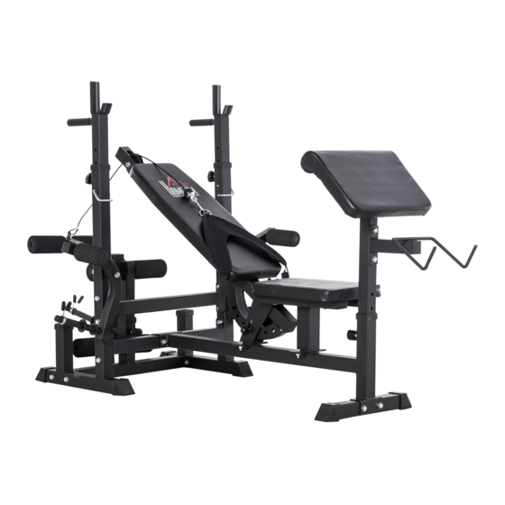
Sommaire des Matières pour HOMCOM A91-131
- Page 1 INamc001V01_FR A91-131 IMPORTANT, RETAIN FOR FUTURE REFERENCE: READ CAREFULLY ASSEMBLY INSTRUCTION...
- Page 2 PACKING DETALS:TOTAL 2 BOXES BOX-1/2 PARTS PARTS BOX-2/2 PARTS PARTS...
- Page 3 PARTS PARTS HARDWARE...
-
Page 4: Table Des Matières
SOMMAIRE CONSIGNES DE SÉCURITÉ........................1 LISTE des pieces............................3 LISTE des piecesSUITE..........................4 LISTE des piecesSUITE..........................5 assemblage ..............................6 Entretien et maintenance ........................12 COMMENCER VOTRE ENTRAÎNEMENT .................... 13 elimination ..............................14... -
Page 10: Assemblage
ASSEMBLAGE Étape 1: • Installez 2 x les couvre-pieds (10), la douille de tube (11) et le couvercle en caoutchouc (18) sur A. • Installez 2 couvre-pieds (10) sur B. • Installez 1 douille de tube (11) sur C et D. •... - Page 11 Étape 2: • Installez 2 bouchons de tube de 38 mm (14) et 1 bouchon de tube de 25 mm (16) et un clip de fixation (19) sur G1 et G2. • Installez H et I sur G1 et G2 avec 1 x boulon et rondelle M8x20 (9) et 1 x boulon et rondelle M10x20 (6).
- Page 12 Étape 3: • Installez 4 x bouchons de tube 60x30 (15) sur K. • Installez 2 bouchons de tube 50x50 (12) et 1 poulie (28), une vis, un écrou et une rondelle M10x65 (4). ~ 8 ~...
- Page 13 Étape 4: • Installez le coussin de siège sur K avec 4 x vis, écrous et rondelles M8x45 (8). • Installez le dossier sur L avec 2 vis, écrous et rondelles M8x65 (7). • Montez les parties L et K avec 4 vis, écrous et rondelles M10x25 (5), 1 vis, écrou et rondelle M12x75 (1) et le boulon de réglage du degré...
- Page 14 Étape 5: • Insérez Q dans M et installez 2 x rouleaux en mousse (22) et un bouchon de tube de Ø 25 mm (16) et 1 x bouchon de tube 45x45 (13). • Insérez 2 x Q, 4 x rouleaux de mousse (22), 5 x bouchons ronds de Ø 25 mm (16).
- Page 15 Étape 6: •Installez P et T sur la partie O avec 2 x vis, écrous et rondelles M10x65 (4) et 4 x vis, écrous et rondelles M8x20 (9). • Ajustez la hauteur avec la goupille (26) après l'avoir insérée dans la partie O.
-
Page 16: Étape 7: Installation De La Pièce De Contrôle De La Montée
Étape 7: Installation de la pièce de contrôle de la montée: • Fixez les boucles de la gourde (27) aux deux extrémités en utilisant le câble (V). La boucle de la gourde relie l'appui-épaule (U) et le câble (V). • Fixez l'angle du dossier avec la goupille à pression (26). ENTRETIEN ET MAINTENANCE 1. -
Page 17: Commencer Votre Entraînement
COMMENCER VOTRE ENTRAÎNEMENT Commencez votre entraînement par un exercice d'étirement. Reportez-vous aux photos ci-dessous. Répétez chaque exercice 3 fois. Étirez chaque bras pendant 15 Maintenez cette position Maintenez cette position secondes pendant 20 secondes pendant 20 secondes Maintenez cette position Maintenez cette position Maintenez cette position pendant 25 secondes... -
Page 18: Elimination
~ 14 ~... - Page 20 CONTENUTI INFORMAZIONI DI SICUREZZA PANORAMICA DELLE PARTI CONTINUAZIONE PANORAMICA DELLE PARTI CONTINUAZIONE PANORAMICA DELLE PARTI ASSEMBLAGGIO CURA E MANUTENZIONE INIZIARE IL VOSTRO ALLENAMENTO SMALTIMENTO...
- Page 26 ASSEMBLY Step 1: • Install 2 x foot covers (10), tube bushing (11) and rubber cover (18) on A. • Install 2 x foot covers (10) on B. • Install 1 x tube bushing (11) on C and D. • Install 14 x M10x70 bolts, nuts, and washers (3) and 2 x M10x75 bolts (2). ~ 6 ~...
- Page 27 Step 2: • Install 2 x 38mm tube plugs (14) and 1 x 25 tube plug (16) and spring clip (19) on G1 and G2. • Install H and I on G1 and G2 with 1 x M8x20 bolt and washer (9) and 1 x M10x20 bolt and washer (6).
- Page 28 Step 3: • Install 4 x 60x30 tube plugs (15) on K. • Install 2 x 50x50 tube plugs (12) and 1 x pulley (28), M10x65 screw, nut, and washer (4). ~ 8 ~...
- Page 29 Step 4: • Install the seat cushion on K with 4 x M8x45 screws, nuts, and washers (8). • Install the backrest on L with 2 x M8x65 screws, nuts, and washers (7). • Install parts L and K with 4 x M10x25 screws, nuts, and washers (5), 1 x M12x75 screw, nut, and washer (1) and the degree adjusting bolt (24).
- Page 30 Step 5: • Insert Q in M and install 2 x foam rollers (22) and Ø 25 mm tube plug (16) and 1 x 45x45 tube plug (13). • Insert 2 x Q, 4 x foam rollers (22), 5 x Ø 25 mm round tube plugs (16). •...
- Page 31 Step 6: •Install P and T on part O with 2 x M10x65 screws, nuts, and washers (4) and 4 x M8x20 screws, nuts, and washers (9). • Adjust the height with popper pin (26) after inserting into part O. ~ 11 ~...
- Page 32 Step 7: Installation of the up raising control part: • Fix the gourd buckles (27) on the two ends when using the cable (V). The gourd buckle connects the shoulder rest (U) and the cable (V). • Fix the angle of the backrest with the popper pin (26). ~ 12 ~...
- Page 33 ~ 13 ~...
- Page 34 ~ 14 ~...


