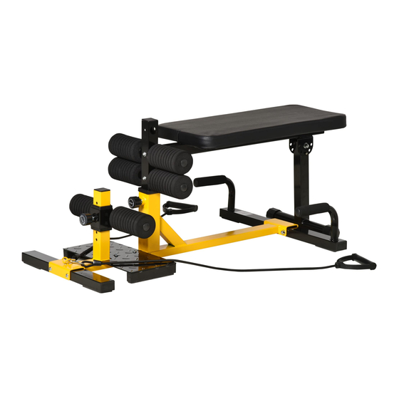
Sommaire des Matières pour HOMCOM A91-182
- Page 1 INala003_FR_EN A91-182_A91-182V01 IMPORTANT, RETAIN FOR FUTURE REFERENCE: READ CAREFULLY USING INSTRUCTION...
- Page 2 IMPORTANTES INFORMATIONS DE SÉCUR FR-2...
- Page 3 SCHÉMA DÉTAILLÉ LISTE DES PIÈCES DESIGNATION NAME Cadre principal Vis M8X70 Stabilisateur arrière Rondelle M8 Plaque antidérapante Ecrou M8 Sous-ensemble réglable Rondelle M6 Stabilisateur avant Vis M6*20 Sous-ensemble Poam Sous-ensemble du banc Poam Goupille Bouton (M16) Montant Vis M8*16 FR-3...
- Page 4 INSTRUCTIONS D’ASSEMBLAGE ÉTAPE 1: sortez les pièces 1 et 5 du carton et posez-les sur le sol. Assemblez les pièces 1 et 5 à l'aide des pièces 10, 11 et 12 ÉTAPE 2: sortez les pièces 1 et 2 du carton et posez-les sur le sol. Assemblez la pièce 1 et la pièce 2 avec la pièce 10, 11, 12 ÉTAPE 3: Assemblez la pièce 3 et la pièce 1 avec la pièce 9 FR-4...
- Page 5 ÉTAPE 4: Installez le Poam 7 dans la pièce 4, puis installez le bouton 8 dans la position debout, vous pouvez régler la hauteur en fonction du bouton 8. ÉTAPE 5: Installez le Poam 7 dans la pièce 6 et la pièce 17, et fixez la pièce 6 avec la vis (pièce 14) ÉTAPE 6: La pièce 15 est sortie de la boîte, tournez-la à...
- Page 6 INala003_FR_EN A91-182_A91-182V01 IMPORTANT, RETAIN FOR FUTURE REFERENCE: READ CAREFULLY USING INSTRUCTION...
- Page 7 IMPORTANT SAFETY INFORMATION EN-2...
- Page 8 EXPLODED DRAWING PARTS LIST NAME NAME Main Frame Screw M8X70 Rear stabilizer Washer M8 Anti-slip plate Nut M8 Adjustable subassembly Washer M6 Front stabilizer Screw M6*20 Poam subassembly Bench Subassembly Poam Knob(M16) Standing Screw M8*16 EN-3...
- Page 9 ASSEMBLE INSTRUCTION STEP 1:put the part 1 and part 5 out of carton and lay them on ground. Put the part 1 and part 5 assemble together by Part 10, 11,12 STEP 2:put the part 1 and part 2 out of carton and lay them on ground. Put the part 1 and part 2 assemble together by Part 10,11,12 STEP 3:Put the part 3 and part 1 assemble together by Part 9 EN-4...
- Page 10 STEP 4:Install Poam 7 into Part 4,Then install Knob 8 into standing,You can adjust the height accoring to Knob 8. STEP 5:Install Poam 7 into Part 6 and Part 17,And fixed part 6 by screw(part 14) STEP 5:Part 15 out of box,Rotate to 90°(as photo show).Then fix by Pin(part 16) Put Part 15 and standing (part 17) together according Part 6.There are 3 holes can be choosed.


