Table des Matières
Publicité
Les langues disponibles
Les langues disponibles
Liens rapides
Publicité
Table des Matières

Manuels Connexes pour FS INTEL XEON RS7260-V2

Sommaire des Matières pour FS INTEL XEON RS7260-V2
- Page 1 RS7260-V2 DUAL INTEL® XEON® SCALABLE PROCESSORS 2U RACKMOUNT SERVER 2HE RACK SERVER MIT ZWEI SKALIERBAREN INTEL® XEON® PROZESSOREN SERVEUR À DEUX PROCESSEURS INTEL® XEON® SCALABLE 2U À MONTAGE EN RACK Quick Start Guide V1.0 Quick-Start Anleitung Guide de Démarrage Rapide...
-
Page 2: Accessories
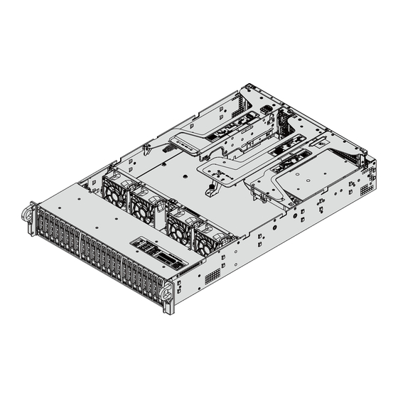
Introduction Thank you for choosing RS7260-V2 Rack Server. This guide is designed to familiarize you with the layout of the server and describes how to deploy the server in your network. RS7260-V2 Accessories RS7260-V2 Rail x2 Power Cable x2 HDD Screw x32 Rail Screw x18 Square hole to round hole adapter x2... -
Page 3: Hardware Overview
Hardware Overview Front View Service/Asset Tag with BMC Password Control Panel Item Description 3.5" hot-swap SAS3*/SATA/NVMe* drive bays (NVMe from CPU1) 6-11 3.5" hot-swap SAS3*/SATA/NVMe* drive bays (NVMe from CPU2) Control Panel Power button UID button/LED BMC Reset Power LED NIC LED NIC LED Power Fail LED... - Page 4 Button/LED Description The main power switch applies or removes primary power from the power supply to the server but maintains standby Power button power. Hold for four seconds to force a shut-down. The unit identification (UID) button turns on or off the blue light function of the Information LED and a blue LED on the UID button/LED rear of the chassis.
-
Page 5: Rear View
Rear View PWS-1 CPU1 CPU2 12 11 Description Riser Networking Slot PCI-E 4.0 x16 Slot (FH, 10.5”L) PCI-E 4.0 x8 (in x16) Slot (FH, 10.5”L) PCI-E 4.0 x8 (in x16) Slot (Internal LP) from CPU2 PCI-E 4.0 x16 Slot (LP) PCI-E 4.0 x8 Slot (FH, 10.5”L) PCI-E 4.0 x8 Slot (FH, 10.5”L) PCI-E 4.0 x8 Slot (FH, 10.5”L) - Page 6 Motherboard Layout Below is a layout of the motherboard with jumper, connector and LED locations shown. See the table on the following page for descriptions. COM1 IPMI_LAN USB0/1(3.0) JUIDB2 JVGA1 LEDM1 BMC P ass word L abel SXB2 JUID IPMI JLAN1 BMC: XXXXXXXXXXXX SXB1A...
- Page 7 Description S-SATA 4, 5: SATA 3.0 Ports (Intel SCU) VROC : Intel VROC Key Header for NVMe RAID BT1 : Onboard CMOS battery JBT1: CMOS Clear SXB3A/3B/3C: Proprietary PCI-e Slot for Riser Devices (x8 From CPU1, x32 From CPU2) JGPW1/JGPW2: GPU 8-pin power connectors P2-DIMMA1/B1/C1/D1(Blue) and P2-DIMMA2/B2/C2/D2(Black) P2-NVMe 9/10: PCI-E 4.0 x8 NVME ports CPU2...
-
Page 8: Installation Requirements
Installation Requirements Before you begin the installation, make sure that you have the following: The system should be situated in a clean, dust-free area that is well ventilated. Avoid areas where heat, electrical noise and electromagnetic fields are generated. A reliable ground must be maintained at all times. Leave enough clearance in front of the rack so that you can open the front door completely (~25 inches) and approximately 30 inches of clearance in the back of the rack to allow sufficient space for airflow and access when servicing. - Page 9 Mounting the Server Installing the Rails Outer Rail Identifying the Rails Middle Rail Locking Tab Inner Rail The chassis package includes two rail assemblies. Each assembly consists of three sections: An inner rail that secures directly to the chassis, an outer rail that secures to the rack, and a middle rail which extends from the outer rail.
- Page 10 1. Pull the inner rail out of the outer rail until it is fully extended as illustrated below. 2. Press the locking tab down to release the inner rail. 3. Pull the inner rail all the way out. Installing the Inner Rails Inner Rails 1.
- Page 11 Installing the Chassis into a Rack Ball-Bearing Shuttle 1. Extend the outer rails as illustrated. 2. Align the inner rails of the chassis with the outer rails on the rack. 3. Slide the inner rails into the outer rails, keeping the pressure even on both sides. When the chassis has been pushed completely into the rack, it should click into the locked position.
- Page 12 Removing the Chassis from the Rack 1. If necessary, loosen the thumb screws on the front of the chassis that hold it in the rack. 2. Pull the chassis forward out the front of the rack until it stops. 3. Press the release latches on each of the inner rails downward simultaneously and continue to pull the chassis forward and out of the rack.
- Page 13 1. Remove the two screws on each side of the cover, which secure the cover to the chassis. These two screws are optional and will not impact functionality if they are not installed. 2. Press the two release buttons and slide the cover toward the rear. 3.
- Page 14 Lever 3. Locate the lever on the carrier and, if necessary, press it down. Latch CPU Key (on the processor) CPU Key (on the carrier) CPU Key (on the processor) CPU Key (on the Latch carrier) 4. Align the CPU keys on the processor (A & B) with those on the carrier (a & b).
- Page 15 Processor Carrier Assembly Processor Carrier Assembly (Top View) (Underside view) 5. Carefully place one end of the processor under latch 1 on the carrier, and then press the other end down until it snaps into latch 2 and is properly seated on the carrier. Heatsink Installation After creating the processor carrier assembly, mount the heatsink onto the carrier assembly to form the processor heatsink module (PHM).
- Page 16 Installing the PHM into the CPU Socke CPU Socket with Plastic Protective Cover Grip Tabs 1. Remove the plastic protective cover from the CPU socket. Gently squeeze the grip tabs then pull the cover off. CPU Socket Threaded Fastener (a, b, c, d: Threaded Fasteners) CPU Socket Pin1 2.
-
Page 17: Top View
A, B, C, D: Peek Nut 1, 2, 3, 4: Rotating Wire a, b, c, d: Threaded Fastener Heatsink Rotating Wire 2 Rotating Wire 4 Rotating Wire 3 Rotating Wire Peek Nut Rotating Wire 1 Peek Nut (Unlatched) (latched) CPU Socket 3. - Page 18 A, B, C, D: Peek Nut on the Heatsink a, b, c, d: Threaded Fastener on the CPU socket 5. Align nut A (next to the triangles and pin 1) on the heatsink with threaded fastener "a" on the CPU socket.
- Page 19 8. With a t30-bit screwdriver, tighten all PEEK nuts in the sequence of A, B, C, and D with even pressure not greater than 12 lbf-in. Installing Memory ESD Precautions Electrostatic Discharge (ESD) can damage electronic components including memory modules. To avoid damaging DIMM modules, it is important to handle them carefully.
- Page 20 2. Align the key of the DIMM with the receptive point on the memory slot and with your thumbs on both ends of the module, press it straight down into the slot until the module snaps into place. 3. Press the release tabs to the locked position to secure the DIMM module into the slot. NOTE: Exercise extreme caution when installing or removing memory modules to prevent damage to the DIMMs or slots.
-
Page 21: Power Supply
1. Remove the dummy drive, which comes pre-installed in the drive carrier. Pull out the two locking clasps on the right outside of the carrier and lift out the dummy drive. 2. Position the drive above the carrier with the PCB side facing down and the connector end toward the rear of the carrier. - Page 22 Power Supply LEDs On the rear of the power supply module, an LED displays the status. • Solid Green: When illuminated, indicates that the power supply is on. • Blinking Green: When blinking, indicates that the power supply is plugged in and turned off by the system.
- Page 23 Internal Expansion Card Expansion Cards 1. Power down the system and remove the top chassis cover. 2. Remove the bracket and sections of the chassis in the rear. 3. If necessary, attach the riser card to the riser card bracket using screws. 4.
-
Page 24: Mounting Bracket
1. Power down the system and remove the top chassis cover. 2. If necessary, remove the full height expansion card to access the low profile riser card slot. 3. Insert the expansion card into the riser card slot while aligning the rear PCI shield into the chassis. Add the screw to secure the PCI shield. - Page 25 Installing the OS 1. Create a method to access the MS Windows installation ISO file. That might be a DVD, perhaps using an external USB/SATA DVD drive, or a USB flash drive, or the IPMI KVM console. 2. Retrieve the proper RST/RSTe driver. Go to the web page for your motherboard and click on "Download the Latest Drivers and Utilities", select the proper driver, and copy it to a USB flash drive.
- Page 26 To load the driver, browse the USB flash drive for the proper driver files. • For RAID, choose the SATA/sSATA RAID driver indicated then choose the storage drive on which you want to install it. • For non-RAID, choose the SATA/sSATA AHCI driver indicated then choose the storage drive on which you want to install it.
- Page 27 3. Select the desired PStack# to Enable or Disable the corresponding Intel VMD controller. Aptio Setup Utility - Copyright (C) 2017 American Megatrends, Inc. Advanced Enable/Disable Intel® VMD Config for PStack0 Volume Management Device Intel® VMD for Volume Management Device [Enable] Technology on specific root VMD Config for PStack1...
- Page 28 NOTE: 1. Disabling the VMD controller without first deleting the associated existing RAID volume can lead to unexpected behavior. This action is strongly not recommended. 2. The effects of physically changing or swapping a CPU on the VMD controller enablement has not yet been thoroughly tested or documented.
- Page 29 10. If cross-controller RAID is required, select Enable RAID spanned over VMD Controller. 11. Select specific disks for RAID with an [X]. • RAID0: Select at least two [2 - 24] disks • RAID1: Select only two disks • RAID5: Select at least three [3 - 24] disks •...
- Page 30 No Power • Check that the power LED on the motherboard is on. • Make sure that the power connector is connected to the power supply. • Check that the motherboard battery still supplies ~3VDC. If it does not, replace it. •...
-
Page 31: Product Warranty
Support and Other Resources Download https://www.fs.com/download.html Help Center https://www.fs.com/service/help_center.html Contact Us https://www.fs.com/contact_us.html Product Warranty Warranty: Rack servers enjoy 3 years labor, 3 years parts limited warranty against defect in materials or workmanship. For more details about warranty, please check at https://www.fs.com/policies/warranty.html... - Page 32 Einführung Vielen Dank, dass Sie sich für den RS7260-V2 Rack Server entschieden haben. Dieses Handbuch soll Sie mit dem Aufbau des Servers vertraut machen und beschreibt, wie Sie den Server in Ihrem Netzwerk einsetzen. RS7260-V2 Zubehör RS7260-V2 Stromkabel x2 Schiene x2 HDD-Schraube x32 Schienenschraube x18 Adapter (quadratisch auf rund) x2...
-
Page 33: Hardware-Übersicht
Hardware-Übersicht Vorderansicht Dienst/Asset-Tag mit BMC-Passwort Bedienfeld Artikel Beschreibung 3,5"-Hot-Swap SAS3*/SATA/NVMe*-Laufwerksschächte (NVMe von CPU1) 6-11 3,5"-Hot-Swap SAS3*/SATA/NVMe*-Laufwerksschächte (NVMe von CPU2) Bedienfeld Power button UID button/LED BMC Reset Power LED NIC LED NIC LED Power Fail LED Information LED... - Page 34 Taste/LED Beschreibung Der Hauptnetzschalter schaltet die Primärstromver- sorgung des Servers ein oder aus, hält aber den Einschalttaste Standby-Betrieb aufrecht. Halten Sie ihn vier Sekunden lang gedrückt, um ein Herunterfahren zu erzwingen. Die Taste zur Geräteidentifikation (UID) schaltet die blaue Lichtfunktion der Informations-LED und eine blaue LED auf UID-Taste/LED der Rückseite des Chassis ein oder aus.
- Page 35 Rückansicht PWS-1 CPU1 CPU2 12 11 Beschreibung Riser Networking-Steckplatz PCI-E 4.0 x16 Steckplatz (FH, 10,5 "L) PCI-E 4.0 x8 (in x16) Steckplatz (FH, 10,5 "L) PCI-E 4.0 x8 (in x16) Steckplatz (Internal LP) von CPU2 PCI-E 4.0 x16-Steckplatz (LP) PCI-E 4.0 x8-Steckplatz (FH, 10,5 "L) PCI-E 4.0 x8-Steckplatz (FH, 10,5 "L) PCI-E 4.0 x8-Steckplatz (FH, 10,5 "L) PCI-E 4.0 x8-Steckplatz (FH, 10,5 "L)
- Page 36 Hauptplatine-Layout Nachfolgend finden Sie ein Layout der Hauptplatine mit den Positionen der Jumper, Anschlüsse und LEDs. Beschreibungen finden Sie in der Tabelle auf der folgenden Seite. COM1 IPMI_LAN USB0/1(3.0) JUIDB2 JVGA1 LEDM1 BMC P ass word L abel SXB2 JUID IPMI JLAN1 BMC: XXXXXXXXXXXX...
- Page 37 Beschreibung S-SATA 4, 5: SATA 3.0-Anschlüsse (Intel SCU) VROC : Intel VROC-Schlüssel-Header für NVMe-RAID BT1 : Onboard CMOS-Batterie JBT1: CMOS löschen SXB3A/3B/3C: Proprietärer PCI-e-Steckplatz für Riser-Geräte (x8 von CPU1, x32 von CPU2) JGPW1/JGPW2: 8-polige GPU-Stromanschlüsse P2-DIMMA1/B1/C1/D1 (Blau) und P2-DIMMA2/B2/C2/D2 (Schwarz) P2-NVMe 9/10: PCI-E 4.0 x8 NVME-Anschlüsse CPU2 P2-NVMe 7/8: PCI-E 4.0 x8 NVME-Anschlüsse...
-
Page 38: Anforderungen An Die Installation
Anforderungen an die Installation Bevor Sie mit der Installation beginnen, vergewissern Sie sich, dass Sie über die folgenden Informationen verfügen: Das System sollte in einem sauberen, staubfreien und gut belüfteten Raum aufgestellt werden. Vermeiden Sie Bereiche, in denen Hitze, elektrisches Rauschen und elektromagnetische Felder erzeugt werden. -
Page 39: Montage Des Servers
Montage des Servers Installation der Schienen Identifizierung der Schienen Äußere Schiene Mittlere Schiene Verriegelungslasche Innere Schiene Das Fahrgestellpaket enthält zwei Schienenbaugruppen. Jede Baugruppe besteht aus drei Teilen: Eine innere Schiene, die direkt am Chassis befestigt wird, eine äußere Schiene, die am Rack befestigt wird, und eine mittlere Schiene, die von der äußeren Schiene ausgeht. - Page 40 1. Ziehen Sie die innere Schiene aus der äußeren Schiene heraus, bis sie vollständig ausgefahren ist, wie unten dargestellt. 2. Drücken Sie die Verriegelungslasche nach unten, um die innere Schiene zu lösen. 3. Ziehen Sie die innere Schiene ganz heraus. Einbau der Innenschienen Innere Schienen 1.
- Page 41 Einbau des Gehäuses in ein Rack Ball-Bearing Shuttle 1. Fahren Sie die äußeren Schienen wie abgebildet aus. 2. Richten Sie die inneren Schienen des Fahrgestells an den äußeren Schienen des Racks aus. 3. Schieben Sie die inneren Schienen in die äußeren Schienen, wobei der Druck auf beiden Seiten gleichmäßig sein muss.
- Page 42 Herausnehmen des Gehäuses aus dem Rack 1. Lösen Sie ggf. die Rändelschrauben an der Vorderseite des Gehäuses, die es im Rack halten. 2. Ziehen Sie das Chassis nach vorne aus dem Rack heraus, bis es anhält. 3. Drücken Sie die Entriegelungslaschen an jeder der inneren Schienen gleichzeitig nach unten und ziehen Sie das Fahrgestell weiter nach vorne und aus dem Gestell heraus.
-
Page 43: Installation Des Prozessors
1. Entfernen Sie die beiden Schrauben auf jeder Seite der Abdeckung, mit denen die Abdeckung am Gehäuse befestigt ist. Diese beiden Schrauben sind optional und haben keinen Einfluss auf die Funktionalität, wenn sie nicht installiert sind. 2. Drücken Sie die beiden Entriegelungstasten und schieben Sie die Abdeckung nach hinten. 3. - Page 44 Hebel 3. Suchen Sie den Hebel am Träger und drücken Sie ihn gegebenenfalls nach unten. Verriegelung CPU-Taste (auf dem Prozessor) CPU-Taste (auf dem Prozessor) CPU-Taste (auf dem Prozessor) CPU-Taste (auf Verriegelung dem Prozessor) 4. Richten Sie die CPU-Tasten am Prozessor (A & B) mit denen am Träger (a & b) aus.
- Page 45 Prozessor-Trägermontage Prozessorträger-Baugruppe (Ansicht von oben) (Ansicht von der Unterseite) 5. Legen Sie ein Ende des Prozessors vorsichtig unter die Verriegelung 1 des Trägers und drücken Sie dann das andere Ende nach unten, bis es in die Verriegelung 2 einrastet und richtig auf dem Träger sitzt.
- Page 46 Einbau des PHM in den CPU-Sockel CPU-Sockel mit Kunststoff-Schutzabdeckung Grifflaschen 1. Entfernen Sie die Kunststoffschutzabdeckung vom CPU-Sockel. Drücken Sie die Grifflaschen leicht zusammen und ziehen Sie die Abdeckung ab. CPU Socket Gewindebefestigung (a, b, c, d: Gewindeverbindungselemente) CPU-Sockel Pin 1 2.
-
Page 47: Ansicht Von Oben
A, B, C, D: Peek Nut 1, 2, 3, 4: Rotierender Draht a, b, c, d: Gewindeverbinder Heatsink Kühlkörper 2 Kühlkörper 4 Kühlkörper 3 Kühlkörper Peek Nut Kühlkörper 1 Peek-Mutter (Unverriegelt) (Verriegelt) CPU-Sockel 3. Suchen Sie die vier PEEK-Muttern (A, B, C, D) und die vier rotierenden Drähte (1, 2, 3, 4) auf dem Kühlkörper. - Page 48 A, B, C, D: Peek-Mutter auf dem Kühlkörper a, b, c, d: Gewindebefestigung am CPU-Sockel 5. Richten Sie die Mutter A (neben den Dreiecken und Stift 1) auf dem Kühlkörper auf die Gewindebe- festigung "a" am CPU-Sockel aus. Richten Sie auch die Muttern B, C, D am Kühlkörper auf die Gewindebefestigungen b, c, d am CPU-Sockel aus.
-
Page 49: Installation Des Speichers
8. Mit einem t30-Bit-Schraubendreher alle PEEK-Muttern in der Reihenfolge A, B, C und D mit gleichmäßigem Druck von höchstens 12 lbf-in anziehen. Installation des Speichers ESD-Vorsichtsmaßnahmen Elektrostatische Entladungen (ESD) können elektronische Komponenten, einschließlich Speicher- module, beschädigen. Um eine Beschädigung der DIMM-Module zu vermeiden, ist es wichtig, sie sorgfältig zu behandeln. - Page 50 Schlüssel 2. Richten Sie den Schlüssel des DIMM auf den Aufnahmepunkt des Speichersteckplatzes aus und drücken Sie das Modul mit den Daumen an beiden Enden gerade nach unten in den Steckplatz, bis das Modul einrastet. 3. Drücken Sie die Entriegelungslaschen in die verriegelte Position, um das DIMM-Modul im Steckplatz zu sichern.
-
Page 51: Stromversorgung
1. Entfernen Sie das Dummy-Laufwerk, das im Laufwerksträger vorinstalliert ist. Ziehen Sie die beiden Verriegelungsklammern an der rechten Außenseite des Trägers heraus und heben Sie das Dummy-Laufwerk heraus. 2. Positionieren Sie das Laufwerk oberhalb des Gehäuses, so dass die PCB-Seite nach unten und das Steckerende zur Rückseite des Gehäuses zeigt. - Page 52 LEDs für die Stromversorgung Auf der Rückseite des Stromversorgungsmoduls befindet sich eine LED, die den Status anzeigt. • Leuchtet grün: Wenn sie leuchtet, bedeutet dies, dass die Stromversorgung eingeschaltet ist. • Blinkt grün: Blinkt, zeigt an, dass das Netzteil eingesteckt und vom System ausgeschaltet ist. •...
- Page 53 Interne Erweiterungskarte Erweiterungskarten 1. Schalten Sie das System aus und entfernen Sie die obere Gehäuseabdeckung. 2. Entfernen Sie die Halterung und die Teile des Fahrgestells auf der Rückseite. 3. Befestigen Sie die Riser-Karte gegebenenfalls mit Schrauben an der Riser-Kartenhalterung. 4. ISetzen Sie die Erweiterungskarte in einen Steckplatz auf der Riser-Karte ein und richten Sie dabei die Rückwand der Erweiterungskarte auf den offenen Steckplatz an der Rückseite des Gehäuses aus.
- Page 54 1. Schalten Sie das System aus und entfernen Sie die obere Gehäuseabdeckung. 2. Entfernen Sie gegebenenfalls die Erweiterungskarte in voller Höhe, um Zugang zum Steckplatz für die Low Profile Riser Card zu erhalten. 3. Setzen Sie die Erweiterungskarte in den Steckplatz der Riser-Karte ein und richten Sie dabei die hintere PCI-Abschirmung am Gehäuse aus.
-
Page 55: Installation Des Betriebssystems
Installation des Betriebssystems 1. Richten Sie eine Methode für den Zugriff auf die MS Windows-Installations-ISO-Datei ein. Das kann eine DVD sein, vielleicht unter Verwendung eines externen USB/SATA-DVD-Laufwerks, eines USB-Flash-Laufwerks oder der IPMI-KVM-Konsole. 2. Rufen Sie den richtigen RST/RSTe-Treiber ab. Gehen Sie auf die Webseite für Ihr Motherboard und klicken Sie auf "Download the Latest Drivers and Utilities", wählen Sie den richtigen Treiber aus und kopieren Sie ihn auf ein USB-Flash-Laufwerk. - Page 56 Um den Treiber zu laden, suchen Sie auf dem USB-Flash-Laufwerk nach den richtigen Treiberdateien. • Für RAID wählen Sie den angegebenen SATA/sSATA-RAID-Treiber und dann das Speicherlaufwerk, auf dem Sie ihn installieren möchten. • Für Nicht-RAID wählen Sie den angegebenen SATA/sSATA AHCI-Treiber und dann das Speicherlauf- werk, auf dem Sie ihn installieren möchten.
- Page 57 3. Wählen Sie die gewünschte PStack#, um den entsprechenden Intel VMD-Controller zu aktivieren oder zu deaktivieren. Aptio Setup Utility - Copyright (C) 2017 American Megatrends, Inc. Advanced Enable/Disable Intel® VMD Config for PStack0 Volume Management Device Intel® VMD for Volume Management Device [Enable] Technology on specific root VMD Config for PStack1...
- Page 58 HINWEIS: 1. Das Deaktivieren des VMD-Controllers ohne vorheriges Löschen des zugehörigen RAID-Volumes kann zu unerwartetem Verhalten führen. Von dieser Aktion wird dringend abgeraten. 2. Die Auswirkungen eines physischen Wechsels oder Austauschs einer CPU auf die Aktivierung des VMD-Controllers wurden noch nicht eingehend getestet oder dokumentiert. 7.
- Page 59 10. Wenn Controller-übergreifendes RAID erforderlich ist, wählen Sie Enable RAID spanned over VMD Controller. 11. Wählen Sie bestimmte Festplatten für RAID mit einem [X] aus. • RAID0: Wählen Sie mindestens zwei [2 - 24] Festplatten • RAID1: Wählen Sie nur zwei Festplatten aus. •...
- Page 60 Keine Macht • Prüfen Sie, ob die Power-LED auf der Hauptplatine leuchtet. • Vergewissern Sie sich, dass der Netzstecker mit dem Stromnetz verbunden ist. • Prüfen Sie, ob die Batterie der Hauptplatine noch ~3VDC liefert. Ist dies nicht der Fall, ersetzen Sie sie.
- Page 61 Support und andere Ressourcen Download https://www.fs.com/de/products_support.html Hilfecenter https://www.fs.com/de/service/fs_support.html Kontakt https://www.fs.com/de/contact_us.htm Produktgarantie Garantie: Rack-Server genießen 3 Jahre Arbeits- und 3 Jahre Ersatzteilgarantie gegen Material- und Verarbeitungsfehler. Weitere Details zur Garantie finden Sie unter https://www.fs.com/de/policies/warranty.html Rückgabe: Wenn Sie Artikel zurückgeben möchten, finden Sie Informationen über die Rückgabe unter...
-
Page 62: Accessoires
Introduction Merci d'avoir choisi le Serveur pour Rack RS7260-V2. Ce guide est conçu pour que vous puissiez vous familiariser avec la configuration du serveur et décrit comment procéder à son déploiement. RS7260-V2 Accessoires RS7260-V2 Rail x2 Câble d'Alimentation x2 Vis du HDD x32 Vis de Rail x18 Adaptateur trou carré... -
Page 63: Aperçu Du Matériel
Aperçu du Matériel Présentation de la Face Frontale Étiquette de Service/Accessoire avec Mot de Passe BMC Panneau de Commande Objet Description Baies de disques durs 3,5" échangeables à chaud SAS3*/SATA/NVMe* (NVMe du CPU1) 6-11 Baies de disques durs 3,5" échangeables à chaud SAS3*/SATA/NVMe* (NVMe du CPU2) Panneau de Contrôle Boutons d'Alimentation... -
Page 64: Couleur, Statut
Bouton/LED Description Le bouton marche/arrêt active ou désactive l'alimentation principale du serveur mais maintient l'alimentation de Bouton secours. Appuyez pendant quatre secondes pour forcer marche/arrêt l'arrêt. Le bouton d'identification de l'unité (UID) permet d'activer ou de désactiver la fonction de lumière bleue du LED Bouton/LED UID d'information et LED bleu à... -
Page 65: Présentation De La Face Arrière
Présentation de la Face Arrière PWS-1 CPU1 CPU2 12 11 N° Description Fente pour Riser 16 Fentes PCI-E 4.0 (FH, 10.5”L) 8 Fentes PCI-E 4.0 (in x16) (FH, 10.5”L) 8 Fentes PCI-E 4.0 (in x16) (LP Interne) du CPU2 16 Fentes PCI-E 4.0 (LP) 8 Fentes PCI-E 4.0 (FH, 10.5”L) 8 Fentes PCI-E 4.0 (FH, 10.5”L) 8 Fentes PCI-E 4.0 (FH, 10.5”L) -
Page 66: Configuration De La Carte Mère
Configuration de la Carte Mère Vous avez ci-dessous une représentation de la carte mère avec l'emplacement des cavaliers, connecteurs et voyants. Voir le tableau de la page suivante pour les descriptions. COM1 IPMI_LAN USB0/1(3.0) JUIDB2 JVGA1 LEDM1 BMC P ass word L abel SXB2 JUID IPMI... - Page 67 N° Description S-SATA 4, 5 : Ports SATA 3.0 (Intel SCU) VROC : Clé Intel VROC pour NVMe RAID BT1 : Batterie CMOS intégrée JBT1 : Cavalier CLEAR CMOS SXB3A/3B/3C : Fente PCI-e pour Dispositifs Riser (x8 du CPU1, x32 du CPU2) JGPW1/JGPW2 : Connecteurs d'alimentation à...
-
Page 68: Exigences D'installation
Exigences d'Installation Avant de commencer l'installation, assurez-vous que vous disposez des éléments suivants : L'appareil doit être placé dans un endroit propre, sans poussière et bien ventilé. Évitez les zones où la chaleur, les perturbations électriques et les champs électromagnétiques sont générés. Il est nécessaire de disposer d'une surface fiable à... -
Page 69: Installation Du Serveur
Installation du Serveur Installation des Rails Rail Extérieur Rail Central Identification des Rails Languette de Verrouillage Rail Intérieur L'ensemble du châssis comprend deux ensembles de rails. Chaque assemblage se compose de trois sections : Un rail intérieur qui se fixe directement au châssis, un rail extérieur qui se fixe à la baie, et un rail intermédiaire qui s'étend à... -
Page 70: Rails Intérieurs
1. Tirez le rail intérieur hors du rail extérieur jusqu'à ce qu'il soit complètement déployé, comme illustré ci-dessous. 2. Appuyez sur l'onglet de verrouillage vers le bas pour libérer le rail intérieur. 3. Tirez le rail intérieur jusqu'au bout. Installation des Rails Intérieurs Rails Intérieurs 1. - Page 71 Installation du Châssis dans un Rack Navette à Billes pour 1. Déployez les rails extérieurs comme illustré. 2. Alignez les rails intérieurs du châssis avec les rails extérieurs du rack. 3. Faites glisser les rails intérieurs dans les rails extérieurs, en maintenant une pression égale des deux côtés.
-
Page 72: Retrait Du Châssis Du Rack
Retrait du Châssis du Rack 1. Si nécessaire, desserrez les vis à oreilles à l'avant du châssis qui maintiennent celui-ci dans le rack. 2. Tirez le châssis en avant jusqu'à ce qu'il s'arrête. 3. Appuyez simultanément vers le bas sur les loquets de libération de chacun des rails intérieurs et continuez à... -
Page 73: Installation Du Processeur
1. Retirez les deux vis situées de chaque côté du couvercle, qui fixent le couvercle au châssis. Ces deux vis sont optionnels et n'auront pas d'impact sur la fonctionnalité si ceux-ci ne sont pas installés. 2. Appuyez sur les deux boutons de déverrouillage et faites glisser le couvercle vers l'arrière. 3. - Page 74 Levier 3. Localisez le levier sur le support et, si nécessaire, appuyez dessus. Loquet Clé CPU (sur le processeur) Clé CPU (sur le support) Clé CPU (sur le processeur) Clé CPU (sur Loquet le support) 4. Alignez les clés CPU du processeur (A et B) avec celles du support (a et b).
-
Page 75: Installation Du Dissipateur Thermique
Ensemble de Support de Processeur Ensemble de Support de Processeur (Vue de Dessus) (Vue de Dessous) 5. Placez délicatement une extrémité du processeur sous le loquet 1 du support, puis appuyez sur l'autre extrémité jusqu'à ce qu'elle s'enclenche dans le loquet 2 et qu'elle soit correctement installée sur le support. -
Page 76: Installation Du Phm Dans Le Socle Du Cpu
Installation du PHM dans le Socle du CPU Socle de CPU avec Couvercle de Protection en Plastique Languettes de Fixation 1. Retirez le couvercle de protection en plastique du socle du CPU. Pressez délicatement les onglets de fixation et retirez le couvercle. Socle de CPU Fixations Filetées (a, b, c, d : Fixations Filetées) -
Page 77: Déverrouillé
A, B, C, D: Écrous Peek 1, 2, 3, 4: Tiges Rotatives a, b, c, d: Fixations Filetées Dissipateur Thermique Fixations Filetées 2 Fixations Filetées4 Fixations Filetées 3 Fixations Filetées Fixations Filetées1 Écrous Peek Écrous Peek (Déverrouillé) (verrouillé) Socle du CPU 3. - Page 78 A, B, C, D: Peek Nut sur le Dissipateur Thermique a, b, c, d: Fixation sur le socket CPU 5. Alignez l'écrou A (à côté des triangles et de la broche 1) sur le dissipateur thermique avec la fixation "a" sur le socle du CPU. Alignez également les écrous B, C, D du dissipateur thermique avec les fixations b, c, d du socle du CPU.
-
Page 79: Installation De La Mémoire
8. À l'aide d'un tournevis T30, serrez tous les écrous PEEK dans l'ordre A, B, C et D avec une pression uniforme. Installation de la Mémoire Précautions contre les Décharges Électrostatiques Les Décharges Électrostatiques (ESD) peuvent endommager les composants électroniques, y compris les modules de mémoire. -
Page 80: Installation Des Disques Durs
Les clés 2. Alignez la fente du module DIMM avec le point de réception de l'emplacement et, en plaçant vos pouces sur les deux extrémités du module, appuyez directement sur celui-ci dans l'emplacement jusqu'à ce que celui-ci s'enclenche. 3. Placez les onglets en position verrouillée pour fixer le module DIMM dans l'emplacement. NOTE : Faites preuve d'une extrême prudence lors de l'installation ou du retrait des modules de mémoire afin d'éviter d'endommager les DIMM ou les fentes. -
Page 81: Installation De La Grille De Ventilation
1. Retirez le disque factice, qui est préinstallé dans le châssis. Tirez sur les deux crochets de verrouillage situés sur l'extérieur droit du châssis et retirez le disque factice. 2. Placez le disque sur le support avec le côté PCB vers le bas et l'extrémité du connecteur vers l'arrière du châssis. -
Page 82: Changement Du Module D'alimentation
Indicateurs LED de l'Alimentation Électrique À l'arrière du module d'alimentation, un indicateur LED affiche l'état. • Vert : Lorsqu'il est allumé, il indique que l'alimentation électrique est activée. • Vert Clignotant : Lorsqu'il clignote, il indique que l'alimentation est branchée et mise hors tension par le système. -
Page 83: Installation De La Carte D'extension Centrale À Profil Bas
Carte d'Expansion Interne Cartes d'Expansion 1. Éteignez le système et retirez le couvercle supérieur du châssis. 2. Retirez le support et les sections du châssis à l'arrière. 3. Si nécessaire, fixez la carte riser au support de la carte riser à l'aide de vis. 4. -
Page 84: Installation De La Carte D'extension Interne
1. Éteignez le système et retirez le couvercle supérieur du châssis. 2. Si nécessaire, retirez la carte d'extension à profil haut pour accéder à l'emplacement de la carte riser à profil bas. 3. Insérez la carte d'extension dans le logement de la carte riser tout en alignant le panneau PCI arrière dans le châssis. -
Page 85: Installation Du Système D'exploitation
Installation du Système d'Exploitation 1. Elaborer une méthode pour accéder au fichier ISO d'installation de MS Windows. Il peut s'agir d'un DVD, en utilisant peut-être un lecteur DVD externe USB/SATA, ou un lecteur flash USB, ou la console KVM IPMI. 2. -
Page 86: Configuration Du Serveur Rack
• Pour RAID, choisissez le pilote RAID SATA/sSATA indiqué puis choisissez le disque de stockage sur lequel vous voulez l'installer. • Pour un système non-RAID, choisissez le pilote SATA/sSATA AHCI indiqué puis choisissez le disque de stockage sur lequel vous voulez l'installer. 5. - Page 87 3. Sélectionnez le PStack# désiré pour activer ou désactiver le contrôleur Intel VMD correspondant. Aptio Setup Utility - Copyright (C) 2017 American Megatrends, Inc. Advanced Enable/Disable Intel® VMD Config for PStack0 Volume Management Device Intel® VMD for Volume Management Device [Enable] Technology on specific root VMD Config for PStack1...
- Page 88 NOTE : 1. La désactivation du contrôleur VMD sans avoir préalablement supprimé le volume RAID existant associé peut entraîner un comportement inattendu. Cette action est fortement déconseillée. 2. Les effets de la modification ou du remplacement physique d'un processeur sur l'activation du contrôleur VMD n'ont pas encore été...
-
Page 89: Dépannage
10. Si le RAID inter-contrôleur est requis, sélectionnez Activer le RAID réparti sur le Contrôleur VMD. 11. Sélectionnez des disques spécifiques pour le RAID avec un [X]. • RAID0 : Sélectionnez au moins deux disques [2 - 24]. • RAID1 : Sélectionnez seulement deux disques. •... -
Page 90: Absence De L'alimentation
Absence de l'Alimentation • Vérifiez que l'indicateur d'alimentation de la carte mère est allumé. • Assurez-vous que le connecteur d'alimentation est connecté à l'alimentation électrique. • Vérifiez que la batterie de la carte mère fournit toujours ~3VDC. Si ce n'est pas le cas, remplacez-la. •... -
Page 91: Support Et Autres Informations
Support et Autres Informations Téléchargez https://www.fs.com/fr/download.html Centre d'Assistance https://www.fs.com/fr/service/help_center.html Contactez-Nous https://www.fs.com/fr/contact_us.html Garantie du Produit Garantie : Le serveur rack bénéficie d'une garantie limitée de 3 ans sur la main-d'œuvre et 3 ans sur les pièces contre les défauts matériels ou de fabrication. Pour plus de détails sur la garantie, veuillez consulter le site https://www.fs.com/fr/policies/warranty.html... -
Page 92: Compliance Information
Any changes or modifications not expressly approved by the grantee of this device could void the user's authority to operate the equipment. Responsible party (only for FCC matter) FS.COM Inc. 380 Centerpoint Blvd, New Castle, DE 19720, United States https://www.fs.com... - Page 93 Die FS.COM GmbH erklärt hiermit, dass dieses Gerät mit der Richtlinie 2014/30/EU und 2014/35/EU konform ist. Eine Kopie der EU-Konformitätserklärung finden Sie unter www.fs.com/de/company/quality_control.html FS.COM GmbH déclare par la présente que cet appareil est conforme à la Directive 2014/30/UE et 2014/35/UE. Une copie de la Déclaration UE de Conformité est disponible www.fs.com/fr/company/quality_control.html FS.COM LIMITED...
- Page 94 Q.C. PASSED 6024 Copyright © 2022 FS.COM All Rights Reserved.