Table des Matières
Publicité
Les langues disponibles
Les langues disponibles
Liens rapides
Publicité
Chapitres
Table des Matières

Manuels Connexes pour Moretti Forni P Serie

Sommaire des Matières pour Moretti Forni P Serie
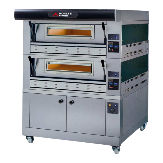
- Page 1 Manuale di istruzioni Instructions manual Manual d’instructions Bedienungsanleitung Manual instrucciones AMALFI P60E-P80E P120E Forno elettrico Electric oven Four electrique Elektrische Ofen Horno El é ctrico Numeri di matricola / Serial numbers: Cod.73340220 Ver.: A11...
-
Page 3: Dichiarazione Ce Di Conformita
- m a i l : m a r k e t i n g @ m o r e t t i f o r n i . c o m DICHIARAZIONE DI CONFORMITA’ MORETTI FORNI S.P.A. Il costruttore Indirizzo del costruttore Via A. - Page 4 We declare under sole responsability that the products to which this declaration relates is in conformity with the following standards <> following the provisions of the directives<>.
- Page 5 INDICE SPECIFICHE TECNICHE INSTALLAZIONE FUNZIONAMENTO MANUTENZIONE ORDINARIA MANUTENZIONE STRAORDINARIA CATALOGHI RICAMBI Nota: Il presente catalogo é predisposto per la lettura in cinque lingue. Istruzioni originali in Italiano e traduzioni delle istruziuoni originali in Inglese, Francese, Tedesco e Spagnolo. GARANZIA Norme e regolamentazione La garanzia è...
- Page 6 SPECIFICHE TECNICHE NOTA: Solo per camere di cottura provviste di vaporiera. DESCRIZIONE DELLE APPARECCHIATURE L’apparecchiatura è costituita da più moduli sovrapposti: - Cappa - Camera/e di cottura - Base - Cavalletto o cella di lievitazione Ogni modulo camera di cottura è totalmente indipendente, ha la ATTENZIONE! Per evitare l’ebollizione, non utilizzare contenitori regolazione della temperatura di tipo elettronico, è...
- Page 7 II tubo per lo scarico dei vapori si trova sul retro del forno (part.C - Per il collegamento alla rete elettrica è necessario installare una spina fig.7). Inserire l'anello forato (part.B - fig.7) nello scarico dei vapori e standardizzata alle norme vigenti. procedere al collegamento.
- Page 8 - Durante il funzionamento le superfici dell’apparecchiatura Quando la somma dei valori fissati per la potenza del cielo (fig.17 part.6) e della platea (fig.17 part.8) è uguale od inferiore a 9, diventano calde, in particolare il vetro, pertanto prestare attenzione a non toccarle per non ustionarsi. l'economizzatore entra in funzione automaticamente e si accende in - All’apertura della porta tenersi a distanza di sicurezza da continuo un led rosso sull'angolo superiore destro del tasto (fig.17...
- Page 9 MEMORIZZAZIONE DI UN PROGRAMMA immissioni di vapore durante l’esecuzione di un programma Premere il tasto “P” (fig.17 part.14). Sul display di sinistra procedendo come di seguito indicato: compare il numero dell’ultimo programma utilizzato, i display di - Premendo il tasto “Boiler/Steam” (fig.17a part.13) è possibile destra visualizzano la temperatura di set point e la potenza di impostare, uno dopo l’altro, il tempo delle tre vaporizzazioni da cielo e platea impostata per tale programma (se si preme ancora il...
- Page 10 - Premendo di nuovo il tasto "Timer" (fig.17 part.15) si visualizza il FERMATA secondo timer di cottura come indica il display cielo (fig.17 part.6), - Spegnere gli interruttori generali del forno (fig.17 part.1) (fig.17a che è possibile impostare come sopra. part.1), delle celle di lievitazione (fig.18 part.3) (fig.19 part.4) e - Una terza pressione permetterà...
- Page 11 ATTENZIONE ISTRUZIONI SEGUENTI RELATIVE ALLA “MANUTENZIONE STRAORDINARIA” SONO STRETTAMENTE RISERVATE PERSONALE TECNICO SPECIALIZZATO MUNITO DI REGOLARE LICENZA, RICONOSCIUTO ED ABILITATO DALLA DITTA COSTRUTTRICE. MANUTENZIONE STRAORDINARIA - Eseguire le operazioni inverse per il rimontaggio, facendo attenzione di collegare i connettori secondo le giuste polarità. OPERAZIONI PRELIMINARI DI SICUREZZA ATTENZIONE! Tutte le operazioni di manutenzione e di 5.3.4...
- Page 12 SOSTITUZIONE PARTI CELLA DI LIEVITAZIONE - Togliere le viti di fissaggio (tav.D) del quadro; - Scollegare i faston,della spia e/o dell'interruttore umidificatore; 5.4.1 SOSTITUZIONE DELLA LAMPADA - Sostituire la spia luminosa (part.3 tav.D); ILLUMINAZIONE - Sostituire l'interruttore umidificatore (part.13 tav.D); Eseguite le operazioni al punto 5.1, la lampada di illuminazione e/o la - Eseguire le operazioni inverse per il rimontaggio.
- Page 13 INDEX TECHNICAL DATA INSTALLATION OPERATION ORDINARY MAINTENANCE SPECIAL MAINTENANCE LIST OF SPARE PARTS Note: This catalogue is printed in five different languages. Original instructions in Italian and translations of the original instructions in English, French, German and Spanish. WARRANTY Standards and rules Warranty only covers the replacement free to factory of pieces eventually broken or damaged because of faulty materials or manufacture.
- Page 14 TECHNICAL DATA NOTE: Only for baking chambers fitted with steamer. DESCRIPTION OF THE OVEN The oven comprises several units positioned one on top of the other: - hood - baking chamber/s - base - lower frame (stand) or leavening compartment Each baking chamber is totally independent and is equipped with WARNING! To avoid scalding, do not use loaded containers with liquids electronic temperature regulator, safety thermostat and with a single...
- Page 15 2.5.1 VAPOUR EXHAUST CONNECTION Insert a cable with an adequate cross-section (see technical data) into the cable raceway provided (fig.13 part B) and connect it to the WARNING! Connection of the vapour exhaust must only be carried out by specialised personnel. terminal board as shown in figure 14.
- Page 16 For more even results, we recommend avoiding the use of temperatures When the sum of the values set for the ceiling (fig.17 item 6) and the above those recommended for the type of product being baked. floor (fig.17 item 8) is higher than 9, the heating elements are fed according to the set values.
- Page 17 It is also possible to associate the “baking Timer” to a program; to DISCHARGING VAPOUR set the timer, press the Timer button (fig. 17 item 15) and the Discharge of the vapours that form inside the baking chamber is display on the left will read “OFF” while the right-hand display enabled using the ball knob on the front left hand side of the oven will show the baking time in: MINUTES “comma”...
- Page 18 - Press the “up” button to set the start-up hour, and the “down” button ROUTINE CLEANING to set the minutes (fig. 17 item 15). After carrying out the operations described in point 4.1 above, clean the - Press the ”Timer” button (fig. 17 item 8) for the sixth time to exit the appliance as follows.
- Page 19 WARNING FOLLOWING INSTRUCTIONS, WHICH CONCERN “SPECIAL MAINTENANCE” ARE STRICTLY RESERVED TO SPECIALIST TECHNICIANS WITH THE RELEVANT LICENSE AS WELL AS BEING APPROVED BY THE MANUFACTURER. SPECIAL MAINTENANCE 5.3.4 REPLACING THE TRANSFORMER PRELIMINARY SAFETY OPERATIONS After carrying out the operations described in 5.1 above, to replace the WARNING! All maintenance operations and repairs must be transformer proceed as follows: carried out using suitable accident prevention equipment, by...
- Page 20 REPLACING PARTS LEAVENING - Disconnect the faston connectors for the indicator and/or the light switch. COMPARTMENT - Replace the indicator light (item 3 plate D). 5.4.1 REPLACING THE LIGHT BULB - Replace the humidifier switch (item 13 plate D). After carrying out the operations described in 5.1 above, to replace the - Perform the above operations in reverse order to reassemble.
-
Page 21: Table Des Matières
TABLE DES MATIÈRES SPECIFICATIONS TECHNIQUES INSTALLATION FONCTIONNEMENT ENTRETIEN ORDINAIRE ENTRETIEN EXTRAORDINAIRE LISTE DES PIECES DE RECHANGE Remarque: Ce catalogue a été rédigé pour la lecture en cinq langues. Instructions originales en italien et traduction des instructions en Anglais, Français, Allemand et Espagnol. -
Page 22: Specifications Techniques
SPECIFICATIONS TECHNIQUES NOTA: Seulement pour les chambres de cuisson munies d’un moyen d’évacuation de vapeur. DESCRIPTION DU FOUR Le four est constitué de plusieurs modules superposés : - Hotte - Chambre/s de cuisson - Soubassement - Tréteau ou étuve Chaque module chambre de cuisson est totalement indépendant, a une régulation de température de type électronique, est doté... -
Page 23: Connexion Evacuation Vapeurs
2.5.1 CONNEXION EVACUATION VAPEURS Le câble du branchement doit être mis à disposition par l’installateur. Pour la connexion au réseau électrique il faut installer une fiche ATTENTION ! La connexion d'évacuation des vapeurs doit être exécutée exclusivement par un personnel spécialisé. conforme aux lois en vigueur. -
Page 24: Mise En Marche De La Chambre De Cuisson Sans Echappement Des Vapeurs
- toutes les opérations de connexion d’évacuation des vapeurs e) Quand la température interne de la chambre de cuisson (fig.17 détail 12) atteint la température programmée (4), l’alimentation se aient été exécutées correctement. Toutes les opérations de contrôle doivent être exécutées par un désactive et la led s’éteint (fig.17 détail 6 et fig.17 détail 8) personnel technique spécialisé... -
Page 25: Mise En Marche De La Chambre De Cuisson Avec Echappement Des Vapeurs
3.2.2 MISE EN MARCHE DE LA CHAMBRE DE CUISSON appuyer et laisser pressée pendant 3 secondes la touche “Economy/Manual” (fig.17a détail 10) pour accéder à la fonction SANS ECHAPPEMENT VAPEURS : MODE PROGRAMS “Manual” A partir du pupitre de commandes, on peut effectuer la mémorisation m) allumer le boiler de l’évacuateur des vapeurs en appuyant sur la de 20 programmes de cuisson différents, pour chaque programme on touche “Boiler/Steam) (fig.17a détail 13). -
Page 26: Choix Entre Degrés Centigrades Et Degrés Fahrenheit
ATTENTION! Eviter le contact avec les résistances: elles peuvent 3.7.5 ACTIVATION DE L’HORLOGE POUR L’ALLUMAGE causer des brûlures. JOURNALIER PROGRAMME - Pour activer l’allumeur programmé, il faut définir une température MISE FONCTION DISTRIBUTEUR désirée et les valeurs du ciel et sole, il faut ensuite entrer dans la fonction de l’heure d’allumage (appuyer 5 fois sur la touche “Timer”... - Page 27 - couvrir l’appareil pour le protéger de la poussière. - aérer régulièrement les locaux. - nettoyer l’appareil avant de le réutiliser. FR/7...
-
Page 28: Entretien Extraordinaire
ATTENTION INSTRUCTIONS SUIVANTES RELATIVES L’“ENTRETIEN EXTRAORDINAIRE ” SONT STRICTEMENT RESERVEES AU PERSONNEL TECHNIQUE SPECIALISE MUNI D’UNE LICENCE SPECIFIQUE, RECONNU ET AGREE PAR LE FABRICANT. ENTRETIEN EXTRAORDINAIRE - Dévisser l’écrou de fixation du thermocouple. - Séparer les deux câbles d’alimentation du thermocouple. OPERATIONS PRELIMINAIRES DE SECURITE - Remplacer le thermocouple (détail 45 tab.A tab.C) (détail 43 tab. -
Page 29: Remplacement De Parties De L'etuve
- Remplacer le thermostat (détail 33 tab. C) (détail 32 tab. A Amalfi) 5.5.2 REMPLACEMENT DE LA LED LUMINEUSE ET/OU avec le capteur relatif et la partie de laine de verre usée si nécessaire. DE L’INTERRUPTEUR HUMIDIFICATEUR - Exécuter les opérations inverses pour remonter l’ensemble. Les opérations du point 5.1 exécutées, pour remplacer la led lumineuse et/ou l’interrupteur lumière, procéder comme suit: - Enlever les vis de fixation (tab. - Page 30 FR/10...
- Page 31 INHALTSVERZEICHNIS TECHNISCHE ANGABEN INSTALLATION BETRIEB WARTUNG AUSSERORDENTLICHE WARTUNG ERSATZTEILKATALOG Hinweis: Vorliegender Katalog ist in fünf Sprachen ausgeführt. Originalanweisungen auf Italienisch und Übersetzungen der Originalanweisungen auf Englisch, Französisch, Deutsch und Spanisch GARANTIE Bedingungen und Vorschriften Die Garantieleistung ist ausschließlich auf den Ersatz jener Teile beschränkt, die festgestellte Material- oder Konstruktionsfehler aufweisen. Der Versand der Teile erfolgt frei Werk.
-
Page 32: Technische Angaben
TECHNISCHE ANGABEN MERKE: Nur für Backöfen, die mit Verdampfer ausgestattet sind. BESCHREIBUNG DES GERÄTES Das Gerät besteht aus mehreren übereinanderliegenden Modulen: - Dunstabzug - Backofen/Backöfen - Boden - Gestell oder Gärschrank Jedes Backofenmodul ist vollkommen unabhängig und verfügt über ACHTUNG! Verwenden Sie zur Vermeidung der Verdampfung keine einen elektronischen Temperaturregler, ein Sicherheitsthermostat bzw. -
Page 33: Betrieb
2.5.1 ANSCHLUSS ABDAMPFLEITUNG Für den Netzanschluss muss ein Netzstecker verwendet werden, der den gletenden Bestimmungen entspricht. ACHTUNG! Anschluss Abdampfleitung darf ausschließlich von Fachpersonal durchgeführt werden. Das Kabel mit geeignetem Querschnitt durch die Kabelführung (Teil B Das Rohr zum Ableiten der Dämpfe befindet sich auf der Rückseite des - Abb.13) ziehen (siehe Technische Daten) und beim Klemmenbrett Ofens (Detail C - Abb.7). - Page 34 Alle Kontrollarbeiten müssen Fachpersonal Wenn die Summe der für die Deckenleistung (Abb. 17 Detail 6) und Bodenleistung (Abb. 17 Detail 8) festgelegten Werte gleich oder vorschriftsmäßiger Lizenz durchgeführt werden. ACHTUNG! geringer als 9 ist, schaltet sich der Sparer automatisch ein und es - Das in Betrieb befindliche Gerät muss überwacht werden.
- Page 35 Programms, auf den rechten Displays werden die für das - Durch Drücken der Taste „Boiler/Steam“ (Abb.17a Detail 13) kann Programm eingestellte Set-Point Temperatur und die Leistungen nacheinander die Dauer der drei während des Backvorgangs der Decke und der Bodenplatte angezeigt (durch erneutes durchzuführenden Verdampfungen eingestellt werden.
-
Page 36: Wartung
- Drückt man nochmals die Taste “Timer” (Abb. 17 Detail 15) kann WAHL ZWISCHEN GRAD CELSIUS UND GRAD der zweite Timer (siehe Deckendisplay) eingestellt werden (Abb. FAHRENHEIT 17 Detail 6). - Bei gleichzeitigem Drücken der Tasten “light” (Abb. 17, Detail 11) - Drückt man ein drittes Mal auf die Taste, wird die Einstellung des und “+ up”... -
Page 37: Ausserordentliche Wartung
ACHTUNG DIE FOLGENDEN ANWEISUNGEN ZUR “AUSSERORDENTLICHEN WARTUNG” RICHTEN SICH AUSSCHLIESSLICH AN FACHPERESONAL MIT ORDENTGEMÄSSER LIZENZ, DAS VOM HERSTELLER ANERKANNT UND BEFUGT IST. AUSSERORDENTLICHE WARTUNG das seitliche Paneel (Detail 29 Taf.A Taf.B) (Detail 22 Taf.C) durch Lösen der Feststellschrauben abnehmen; EINLEITENDE SCHUTZMASSNAHMEN die Schraubenmutter des Thermoelements abschrauben;... -
Page 38: Ersatzteilkatalog
- Das rechte Seitenpaneel abnehmen, indem die vier Fixierschrauben AUSTAUSCH VON TEILEN DES GÄRSCHRANKES MIT gelöst werden. LUFTBEFEUCHTER - Den Sensor des Thermostates, der sich innerhalb der isolierenden Steinwolle befindet, herausnehmen, indem der betreffende Teil der 5.5.1 AUSTAUSCH DES WIDERSTANDES DER WANNE Steinwolle mit einer Klinge entfernt wird . - Page 39 ÍNDICE CARACTERÍSTICAS TÉCNICAS INSTALACIÓN FUNCIONAMIENTO MANTENIMIENTO ORDINARIO MANTENIMIENTO EXTRAORDINARIO CATÁLOGO DE LOS RECAMBIOS Nota: El presente manual se ha previsto para la lectura en cinco idiomas. Instrucciones originales en Italiano y traducciones de las instrucciones originales en Inglés, Francés, Alemán y Español. GARANTÍA Normas y reglamentación La garantía se limita a la pura y simple sustitución franco de fábrica de la pieza eventualmente rota o defectuosa sólo en caso de defecto del material o de...
- Page 40 CARACTERÍSTICAS TÉCNICAS NOTA: Sólo para las cámaras de cocción con equipo de vapor. DESCRIPCIÓN DE LOS APARATOS El aparato está formado por varios módulos sobrepuestos: - Campana - Cámara/s de cocción - Base - Caballete o cámara de fermentación Cada cámara de cocción es totalmente independiente, la temperatura se ¡ATENCIÓN! Para evitar el ebullición, no utilizar contenedores llenos regula de manera electrónica y posee un termostato de seguridad y una de líquidos o alimentos que se licúan con el calor, en cantidad superior...
- Page 41 2.5.1 CONEXIÓN DE LA DESCARGA DE LOS VAPORES El cable de conexión tiene que ser suministrado por el instalador. Para la conexión a la red eléctrica hay que instalar un enchufe que esté ¡ATENCIÓN! La conexión de la descarga de los vapores tiene que ser efectuada sólo y exclusivamente por personal cualificado.
- Page 42 Todas las operaciones de control tienen que ser efectuadas por El sistema de control del horno posee un economizador que puede activarse de forma automática o manual. personal técnico especializado que posea la debida licencia. ¡ATENCIÓN! f.1) Activación automática del economizador - Vigilar el aparato mientras esté...
- Page 43 3.2.2 PUESTA MARCHA CÁMARA pulsar y mantener apretada durante 3 segundos la tecla “Economy/Manual” (fig.17a part.10) para acceder a la función COCCIÓN EQUIPO VAPOR: MODO PROGRAMS “Manual” Desde el cuadro de mandos es posible efectuar la memorización de m) encender la caldera del equipo de vapor pulsando la tecla n°20 programas de cocción distintos, para cada programa podremos “Boiler/Steam) (fig.17a...
- Page 44 b) Programar la temperatura deseada hasta un valor máximo de 65ºC. - Una vez acabado el tiempo del temporizador se apagarán todos los c) Añadir agua en el depósito del humectador en el interior de la displays, se encenderá el LED temporizador (fig.17 part.15) y cámara de fermentación.
- Page 45 No utilizar solventes, productos detergentes que contengan sustancias agresivas (cloradas, ácidas, corrosivas, abrasivas, etc…) o utensilios que puedan dañar las superficies; antes de volver a encender el aparato, prestar atención en no dejar dentro del mismo lo que ha sido utilizado para la limpieza. PERIODOS DE INACTIVIDAD Si el aparato no se tiene que utilizar durante largos periodos: - Desenchufarlo de la alimentación eléctrica.
- Page 46 ATENCIÓN SIGUIENTES INSTRUCCIONES RELATIVAS “MANTENIMIENTO EXTRAORDINARIO” ESTÁN RESERVADAS PERSONAL TÉCNICO ESPECIALIZADO EN POSESIÓN DE UNA REGULAR LICENCIA, AUTORIZADO Y HABILITADO POR EL FABRICANTE. MANTENIMIENTO EXTRAORDINARIO - Quitar el panel lateral (ref. 29, tabla A y tabla B) (ref. 22, tabla C) tras desenroscar los cuatro tornillos de fijación;...
- Page 47 - Quitar el sensor del termostato, situado en el interior de la lana de - Desconectar los cables de alimentación de la resistencia (ref. 19, roca aislante tras quitar con una cuchilla la parte de lana de roca tabla D). deseada.
- Page 48 ES/10...
- Page 49 P60E–P80E PIZ P60E P80E P60E P80E P60E P80E P60E P80E P60E P80E P60E P80E P60E P80E P60E P80E...
- Page 50 P120E PIZ P120E K P120E C18 P120E B P120E L80 P120E S60 P120E S80 P120E S95...
- Page 51 AMALFI PIZ AMALFI K AMALFI C18 AMALFI B AMALFI L AMALFI S60 AMALFI S80 AMALFI S95...
- Page 52 P60E–P80E PAS P60E P80E P60E P80E P60E P80E P60E P80E P60E P80E P60E P80E P60E P80E P60E P80E P60E P80E...
- Page 53 P120E PAS P120E K P120E C18 P120E C30 P120E B P120E L80 P120E S60 P120E S80 P120E S95...
- Page 54 P60E-P80E PIZ P60E C P80E C P60E-P80E L P60E-P80E LU P60E-P80E KX 18 PIZ 18 PIZ Potenza Max (kW) Puissance Max. (kW) Maximum power (kW) Höchstleistung (kW) 1,75 0,25 Potencia máx (kW) Assorbimento nominale (kWh) Absorption nominale (kWh) Rated absorption (kWh) Soll-Stromaufnahme (kWh) 0,75 0,875...
- Page 55 P60E-P80E PAS P60E C P80E C P60E-P80E L P60E-P80E LU P60E-P80E KX 18/30PAS 18/30PAS Potenza Max (kW) Puissance Max. (kW) Maximum power (kW) Höchstleistung (kW) 10,1 1,75 0,25 Potencia máx (kW) Assorbimento nominale (kWh) Absorption nominale (kWh) Rated absorption (kWh) Soll-Stromaufnahme (kWh) 4,25 5,05...
- Page 56 AMALFI K P60E K P80E K P120E K AMALFI KX P60E KX P80E KX P120E KX...
- Page 58 Fig. 18...
- Page 61 Denominazione Denomination Designation Bezeichnung Denominación 2 Perno Pivot Bolzen Perno 3 Blocchetto Joint Plate Platine Fixierscheibe Palastro 4 Vetro Glass Verre Scheibe Vidrio 6 Boccola Bush Douille Büchse Anillo 7 Perno Pivot Bolzen Perno 8 Maniglia Handle Poignée Griff Manija 9 Cerniera Sn.
- Page 63 Rif. Denominazione Denomination Designation Bezeichnung Denominación 2 Perno Pivot Bolzen Perno 3 Blocchetto Joint Plate Platine Fixierscheibe Palastro 4 Vetro Glass Verre Scheibe Vidrio 6 Boccola Bush Douille Büchse Anillo 7 Perno Pivot Bolzen Perno 8 Maniglia Handle Poignée Griff Manija 9 Cerniera Sn.
- Page 64 14 P120C/AB PIZ. 12 P120C/A PIZ. 15 P120C/C PIZ. 13 P120C/B PIZ. 13 P120C/C PAS. 14 P120C/C PIZ. 12 P120C/C PAS. 12 P120C/AC PIZ. -12 P120C/C PAS. 13 P120C/B PIZ.
- Page 65 Rif. Denominazione Denomination Designation Bezeichnung Denominación 4 Vetro Glass Verre Scheibe Vidrio 6 Perno Pivot Bolzen Perno 7 Blocchetto Joint Plate Platine Fixierscheibe Palastro 9 Cerniera Sn. Left Hinge Charnière Gauche Linkes Scharnier Bisagra Izquierda 10 Perno Pivot Bolzen Perno 11 Molla Spring Ressort...
- Page 67 Denominazione Denomination Designation Bezeichnung Denominación 2 Pomello Ball knob Pommeau Kugelgriff Pomo 3 Spia umidificatore Humidifier indicator light Humidificateur Led Kontrolllampe Luftbefeuchter Testigo del humectador 4 Interruttore luce Light switch Interrupteur lumière Lichtschalter Interruptor de la luz 5 Manopola Dial Poignée Drehknopf Mando...
- Page 69 Denominazione Denomination Designation Bezeichnung Denominación Vaporiera Steamer vaporisateur Dampferzeuger- equipo vapor Resistenza Heating element Résistance Widerstand Resistencia Elettrovalvola Solenoid valve Électrovanne Magnetventil Electroválvula Contattore. Contactor Contacteur Kontaktgeber Contactor Soppressore Suppressor Suppresseur Entstörer Supresor Termostato Thermostat Thermostat Thermostat Termóstato Tubo entrata acqua Water inlet tube Tuyau d'arrivée d'eau Wasser Einlauf Schlauch...
- Page 70 V. 400 3F+N+PE 50Hz V. 230 3F+PE 50Hz PONTICELLO 9 10 11 41 40 38 39 V. 400 V. 400 V. 230 V. 230 74821580 Revisione 03 MOD. P60C - P80C 18/30 V400 3N V230 3...
- Page 71 Rif. Denominazione Designation Denomination Bezeichnung Denominación Entrata rete Mains junction box Entrée réseau Netzeingang Borne de conexión a la red Resistenze cielo Ceiling heating elements Résistances ciel Widerstand oben Resistencia de la parte superior Resistenze platea Floor heating elements Résistances sole Widerstand unten Resistencia de la parte inferior Contattore cielo...
- Page 72 V. 400 3F+N+PE 50Hz V. 230 3F+PE 50Hz PONTICELLO 33 34 21 22 23 25 26 24 25 26 V. 230 V. 230 V. 400 V. 400 74821040 Revisione 03 MOD. AMALFI C 18 A-B-C V400 3N V230 3...
- Page 73 Rif. Denominazione Designation Denomination Bezeichnung Denominación Entrata rete Mains junction box Entrée réseau Netzeingang Borne de conexión a la red Resistenze cielo Ceiling heating elements Résistances ciel Widerstände oben Resistencia de la parte superior Resistenze platea Floor heating elements Résistances sole Widerstände unten Resistencia de la parte inferior Contattore cielo...
- Page 74 V400 3F+N+PE 50/60Hz V230 3F+PE 50/60Hz PONTICELLO V230 V400 74800680 Revisione 01 MOD. AMALFI C 18 D V400 3N V230 3...
- Page 75 Rif. Denominazione Designation Denomination Bezeichnung Denominación Entrata rete Mains junction box Entrée réseau Netzeingang Borne de conexión a la red R7-12 Resistenze cielo Ceiling heating elements Résistances ciel Widerstände oben Resistencia de la parte superior R1-6 Resistenze platea Floor heating elements Résistances sole Widerstände unten Resistencia de la parte inferior...
- Page 76 V. 400 3F+N+PE 50Hz V. 230 3F+PE 50Hz PONTICELLO 25 26 25 26 14 10 1 2 3 31 35 43 47 V. 400 V. 400 V. 230 V. 230 VAPORIERA 1600W VAPORIERA 3200W 74821440 Revisione 04 MOD. P120C 18/30 A-B V400 3N V230 3...
- Page 77 Rif. Denominazione Designation Denomination Bezeichnung Denominación Entrata rete Electrical junction box Plaque branchement électrique Klemme elektro Anschluss Borne de conexión a la red Resistenze cielo Heating element ceiling Résistance ciel Heizelement oben Resistencia superior Resistenze platea Heating element bottom Résistance plan de cuisson Heizelement unten Resistencia inferior Contattore cielo...
- Page 78 V. 400 3F+N+PE 50Hz V. 230 3F+PE 50Hz PONTICELLO 24 25 24 25 27 31 43 39 V. 230 V. 400 V. 400 V. 230 VAPORIERA 1600W VAPORIERA 3200W 74821460 Revisione 04 MOD. P120C 18/30 C V400 3N V230 3...
- Page 79 Rif. Denominazione Designation Denomination Bezeichnung Denominación Entrata rete Mains junction box Entrée réseau Netzeingang Borne de conexión a la red Resistenze cielo Ceiling heating elements Résistances ciel Widerstände oben Resistencia de la parte superior Resistenze platea Floor heating elements Résistances sole Widerstände unten Resistencia de la parte inferior Contattore cielo...
- Page 80 P60E/P80E/P120E/AMALFI L P60E/P80E/P120E LU V230 1N...
- Page 81 Rif. Denominazione Designation Denomination Bezeichnung Denominación Interruttore luce camera Internal light switch Interrupteur lumière chambre Lichtschalter Ofen Interruptor de la luz cámara Interruttore resistenza umidificatore Humidifier heating element switch Interrupteur résistance humidificateur Schalter Widerstand Luftbefeuchter Interruptor resistencia del humectadores Interruttore termostato Thermostat switch Interrupteur thermostat Thermostatschalter...
- Page 82 230V 50Hz 74822530 Revisione 02 MOD. P60/P80/P120/AMALFI KX-F80 KX-iD KX V2301N...
- Page 83 Rif. Denominazione Designation Denomination Bezeichnung Denominación Interruttore Switch Interrupteur Schalter Interruptor Motore elettrico Motor Moteur Motor Motor Condensatore Condenser Condenseur Kondensator Condensador 74822530 P60E/P80E/P120E/AMALFI KX –F80 KX – iD KX V230 1N...