
Manuels Connexes pour Parker 250


Sommaire des Matières pour Parker 250
- Page 1 User manual Manuel d’utilisation Refrigeration Dryer (60Hz) Manual de uso DATE: 01.07.2013 - Rev. 16 CODE: 398H272915...
-
Page 3: Table Des Matières
Index Safety Th e manufacturer declines and present or future liability for damage to persons, things and the machine, due to negligence of the operators, 1 Safety Importance of the manual non-compliance with all the instructions given in this manual, and non- Importance of the manual application of current regulations regarding safety of the system. -
Page 4: Introduction
English Introduction Operating space Starting • Start the dryer before the air compressor; Th is manual refers to refrigeration dryers designed to guarantee high Leave a space of 60 inches (1.5 m) around the unit.Leave a space & • switch the power on by turning the MAIN SWITCH to “I ON”: quality in the treatment of compressed air. -
Page 5: Control
Control Keyboard mode STANDARD MENU* Do not activate ON status (refrigeration compressor operating) Control panel more than 10 times in one hour. Scheduled maintenance Switching no/off Confi rm Display When the DISPLAY alternatively shows the Sr warning ON/OFF BUTTON code and dew point, contact authorized assistance personnel for carry- ing out scheduled maintenance indicated in par. -
Page 6: Parameters
English List of alarm/warnings Must be set to “0”. To view the details of the event, press High Pressure alarm Operating logic of the alarm/machine status relay. 0 = relay energised when dryer is running, de-energised if Phases monitor alarm 1 Alarm code in warning/alarm status. -
Page 7: Maintenance
Maintenance Preventive Maintenance Programme Dismantling To guarantee lasting maximum dryer effi ciency and reliability Th e refrigerant and the lubricating oil contained in the circuit must be • Th e machine is designed and built to guarantee continuous opera- recovered in conformity with current local environmental regulations. Maintenance Maintenance Interval tion;... -
Page 8: Troubleshooting
English troubleshooting REMEDY FAULT CAUSE Lt Low evaporation tempera- Low pressure High dew point Compressor ture alarm High pressure High temperature alarm warning noisy alarm Ld Low dew point alarm alarm Replace Compressor Decrease Low cooling air Clean pressure Cooling air high Cooling air high components Low pressure... -
Page 9: Y Z
Sommaire Sécurité Il incombe à l’utilisateur d’analyser tous les aspects de l’application pour laquelle l’unité est installée, de suivre toutes les consignes industrielles 1 Sécurité Importance de la notice de sécurité applicables et toutes les prescriptions inhérentes au produit Importance de la notice contenues dans le manuel d’utilisation et dans tout autre documentation •... -
Page 10: Introduction
Français ner au vendeur. 0.12 pouces (3 mm) (voir réglementation locale en vigueur en la matière Partie Risque Modalité Précautions et s’y conformer). concernée résiduel Procédure Le courant nominal “In” de ce disjoncteur magnéto-thermique doit être Installer le sécheur en un endroit propre et à l’abri des intempéries et du partie interne intoxica- défaut d’isolation des... -
Page 11: Arrêt
• Laisser le sécheur en fonction pendant toute la période de fonc- Eteint = aucune signalisation X4.0 X4.10 X4.0 X4.10 tionnement du compresseur d’air ; Clignote = Alarme ou avertisse- d’ A vertissement • le sécheur fonctionne en mode automatique et donc ne nécessite ment. -
Page 12: Paramètres
Français é 1) localiser et éliminer la cause ; Non disponibile avec 2) appuyer sur pour acquitter l’alarme ; Chaque évènement est visualisé par “ALX” (X= 1-8). Modèle sécheur: AL1 = évènement plus récent. Mon = modèles 3) appuyer sur pour redémarrer le sécheur. -
Page 13: Entretien
Entretien Programme d’entretien préventif • kits vanne automatique d’ e xpansion; b) pièces détachées Pour une effi cacité et une fi abilité maximales durables du sécheur, eff ec- • La machine est conçue et construite pour garantir un fonction- tuer : Mise au rebut nement continu ;... -
Page 14: Dépannage
Français Dépannage SOLUTION PANNE CAUSE Alarme basse température Alarme haute Alarme Alarme haute Signalisation Compresseur pression d’ é vaporation Lt. basse pression température haut point de Bruyant Ld Alarme Bas Point de Rosée. roséeg Augmenter la Composants Baisser la Basse tempéra- Pressostat basse Remplacer le Haute tempéra-... -
Page 15: Y Z
Índice Seguridad La alteración o sustitución de cualquier componente por parte del per- sonal no autorizado, así como el uso inadecuado de la unidad eximen 1 Seguridad Importancia del manual de toda responsabilidad al fabricante y provocan la anulación de la ga- Importancia del manual rantía. -
Page 16: Introducción
Español Respete las indicaciones dadas en los apartados 8.2 y 8.3. Parte del Riesgo Modo Precauciones Para conectar el equipo al sistema de drenaje, evite la conexión en equipo residual Todos los secadores deben contar con una adecuada prefi ltración insta- circuito cerrado en común con otras líneas de descarga presurizadas. -
Page 17: Parada
evitar sobrecargar la secadora. No active el estado ON (compresor frigorífi co en marcha) más de • Evite fl uctuaciones de temperatura del aire entrante Modo teclado STANDARD MENU* diez veces por hora. Parada Mantenimiento programado • Pare el secador dos minutos después de haber detenido el compre- Cuando la PANTALLA muestre alternadamente el códi- Encender y apagar... -
Page 18: Parámetros
Español Para visualizar los detalles del evento presionar x: Lista de alarms y avisos No disponibile Alarma Alta presión Tiene que ser defi nido a “0”. 1 Código de alarma Alarma Fases invertidas Lógica del funcionamiento del relé de alarma/estado de má- 2 Millar horas Alarma Baja presión quina. -
Page 19: Mantenimiento
Mantenimiento Desguace Acciones Intervalo de tiempo (condiciones de funcionamiento El fl uido refrigerante y el aceite lubricante contenidos en el circuito de- de mantenimiento • El equipo ha sido diseñado y realizado para funcionar de manera estándar) ben recogerse de conformidad con las normas locales. continua. -
Page 20: Solución De Problemas
Español Solución de problemas SOLUCIÓN FALLO CAUSA Alarme alta Alarma baja temperatura Alarme baja Alarme alta tem- Compresor Aviso alto punto de presión evaporación Lt presión peratura ruidoso rocío. Alarma bajo punto de rocío Ld Sí Sí Sí Sí Sí Sí... - Page 21 Appendix Simbol FR/ES /EN Simbol FR/ES /EN Niveau de pression sonore à 1 mètre de distance en champ libre Pressostat ventilateur / Presostato ventilador (selon norme ISO 3746). Fan pressure switch Simbol FR/ES /EN Nivel de presión sonora (a 1 m de distancia en campo libre, según Pois / Peso norma ISO 3746) Pressostat haute pression/Presostato alta presión...
- Page 22 8.1 Legend Simbol FR/ES /EN Simbol FR/ES /EN Sorties numériques/Salidas digitales Interrupteur magnéto-thermique diff érentiel Digital Outputs Interruptor magnetotérmico diferencial Residual-current circuit breaker Entrées analogiques/Entradas analógicas Analog Inputs Panneaux/Paneles Panels Def remoto/Apagado remoto Remote Off Interrupteur automatique moteur compresseur Interruptor automático motor compresor Compressor motor automatic switch Transformateur auxiliaires Transformador auxiliar...
- Page 23 Compresseur d’air Sécheur Filtre (fi ltration des particules de 3 microns minimum) à proximité de l’ o rifi ce d’admission d’air du sécheur Groupe by-pass Compresor de aire Secador Filtro (fi ltración de 3 micrones o mejor) cerca de la entrada de aire de la sec adora Grupo by-pass Air compressor Dryer...
- Page 24 8.3 Technical data MIN.- MAX Compressed Sound Ambient Temperature Weight Air - Side air inlet Refrigerant Compressed pressure level air outlet air inlet Condensate drain Working R134a (Kg) Temperature Pressure Model During transpor Aft er and stokage installation (lb) (Kg) (oz) (Kg) [dB (A)]...
- Page 25 Paragraph Component (8.5/8.8) 3 year preventive maintenance kits 230V/1Ph/60Hz 6 / 12 / 15 B1 B3 C2 C3 398H473899 230V/3Ph/60Hz 6 / 12 / 15 B1 B3 C3 398H473898 460V/3Ph/60Hz 230V/1Ph/60Hz 398H473897 Compressor kit 230V/3Ph/60Hz 1 / 8 KM1 398H473896 460V/3Ph/60Hz 398H473893 230V/1Ph/60Hz...
- Page 26 8.4 Spare parts list Paragraph Component (8.5/8.8) 230V/1Ph/60Hz 398H256421 Main disconnector switch 230V/3Ph/60Hz 460V/3Ph/60Hz 398H256416 230V/1Ph/60Hz 398H256285 Compressor motor automatic switch 230V/3Ph/60Hz 398H256222 460V/3Ph/60Hz 398H256287 230V/1Ph/60Hz 398H256372 Auxiliary transformer 230V/3Ph/60Hz 460V/3Ph/60Hz 398H256375 230V/1Ph/60Hz Fuses 230V/3Ph/60Hz FU1-2 398H254692 460V/3Ph/60Hz 230V/1Ph/60Hz 398H254775 Fuses 230V/3Ph/60Hz 398H254778...
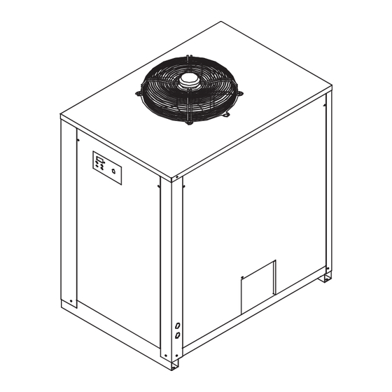
- Page 27 8.5 Exploded drawing 250...
- Page 28 8.6 Dimensional 250 [ i n c h e s ] c e n t e r o f g r a v i t y p o s i t i o n...
- Page 29 8.7 Refrigerant circuit 250...
- Page 30 8.8 Wiring diagram (230V/1Ph/60Hz)
- Page 31 8.8 Wiring diagram (230V/1Ph/60Hz)
- Page 32 8.8 Wiring diagram (230V/1Ph/60Hz)
- Page 33 8.8 Wiring diagram (230V/1Ph/60Hz)
- Page 34 8.8 Wiring diagram (230V/1Ph/60Hz)
- Page 35 8.8 Wiring diagram (230V/3Ph/60Hz)
- Page 36 8.8 Wiring diagram (230V/3Ph/60Hz)
- Page 37 8.8 Wiring diagram (230V/3Ph/60Hz)
- Page 38 8.8 Wiring diagram (230V/3Ph/60Hz)
- Page 39 8.8 Wiring diagram (230V/3Ph/60Hz)
- Page 40 8.8 Wiring diagram (230V/3Ph/60Hz)
- Page 41 8.8 Wiring diagram (460V/3Ph/60Hz)
- Page 42 8.8 Wiring diagram (460V/3Ph/60Hz)
- Page 43 8.8 Wiring diagram (460V/3Ph/60Hz)
- Page 44 8.8 Wiring diagram (460V/3Ph/60Hz)
- Page 45 8.8 Wiring diagram (460V/3Ph/60Hz)
- Page 46 8.8 Wiring diagram (460V/3Ph/60Hz)
- Page 47 Know-how associated with the goods and required for such re- with Seller’s instructions (i.e., the Parker User Manual) and, where necessary, connected to adequate elec- sale, all of which nonetheless remain the exclusive property of Seller. Any other utilization of the Intellectual tric, water and drain services, cleaned out correctly and placed into operation by a qualifi ed technician.
- Page 48 La garantie est valide uniquement si les produits ont été installés, démarrés et entretenus en accord avec les instructions de la société fournisseur (p. ex., Manuel d’utilisation Parker) et, là où nécessaire, reliés à Propriété intellectuelle un secteur électrique adéquat, au réseau hydrique et d’...
- Page 49 La garantía es válida sólo en caso de instalación, puesta en marcha y mantenimiento de los produc- quier otra pérdida económica directa o indirecta. Esto se aplica durante y después del periodo de garantía. tos conforme a las instrucciones del Proveedor (consulte el Manual de Usuario Parker) y, si procede, Propiedad intelectual conexión a la red eléctrica, hídrica y de evacuación, limpieza y puesta en marcha correctamente realizadas...
- Page 52 A division of Parker Hannifi n Corporation Parker Hannifi n Corp. Finite Airtek Filtration Division 4087 Walden Avenue Lancaster, NY 14086 Tel. 716 686 6400, Fax 877 857 3800...