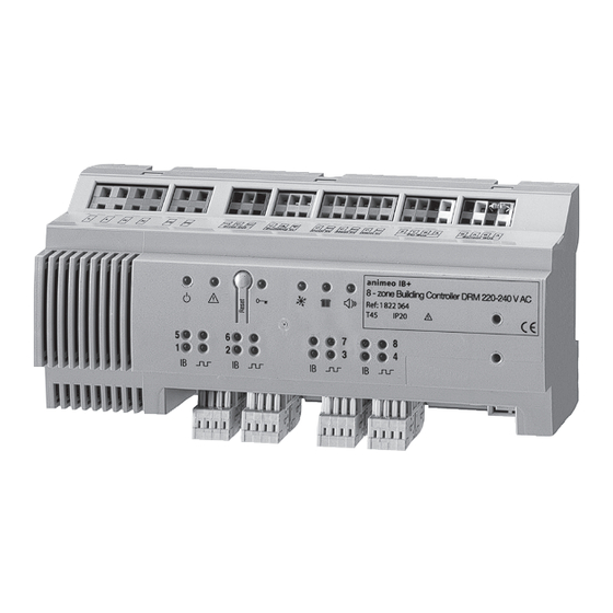
SOMFY animeo IB+ Notice D'utilisation
Masquer les pouces
Voir aussi pour animeo IB+:
- Notice d'installation (24 pages) ,
- Mode d'emploi (4 pages) ,
- Notice d'installation (16 pages)
Publicité
Liens rapides
Ref. 1822395 (4 zone 220 - 230 V AC)
Ref. 1822064 (8 zone 220 - 230 V AC)
Ref. 1822065 (8 zone 100 - 120 V AC)
animeo
IB+ Building Controller
Gebrauchsanweisung
Installationsvejledning
Installation guide
© 2009-2017, SOMFY ACTIVITÉS SA. ALL RIGHTS RESERVED. REF. 5007653E – 2017/12/04
®
Guía de instalación
Notice d'installation
Guida all'installazione
SOLUTIONS FOR BUILDING CONTROL
Montagehandleiding
Installasjonsanvisninger
Installationsanvisningar
Publicité

Sommaire des Matières pour SOMFY animeo IB+
- Page 1 Ref. 1822065 (8 zone 100 - 120 V AC) SOLUTIONS FOR BUILDING CONTROL animeo ® IB+ Building Controller Gebrauchsanweisung Guía de instalación Montagehandleiding Installationsvejledning Notice d‘installation Installasjonsanvisninger Installation guide Guida all‘installazione Installationsanvisningar © 2009-2017, SOMFY ACTIVITÉS SA. ALL RIGHTS RESERVED. REF. 5007653E – 2017/12/04...
- Page 2 DIN rail 210 = 12 SU 90 mm Mains max: 2.5 mm 0.4 mm > 10 cm Mains 2/12 animeo IB+ BUILDING CONTROLLER. REF. 5007653E -...
- Page 3 L L N N Y B A A B A Error out Building in Cool in Heat in Alarm in PC Bus Sensor Bus Somfy animeo IB+ ❄ Building Controller DRM 1822395/1822064/1822065 ❄ Out 5 Out 2 Out 3 Out 4...
- Page 4 > 5 s > 5 s 4/12 animeo IB+ BUILDING CONTROLLER. REF. 5007653E -...
- Page 6 PC-Bus (Ein-/Ausgang) PC bus (Ind/Ud) Sensor-Bus (Ein-/Ausgang) Sensor bus (Ind/Ud) Somfy IB und IB+ Steuerleitung (Ausgang) Somfy IB og IB+ bus (Ud) (Für Kabeltyp und -länge siehe auch Tabelle S. 6) (Se kabeltype og længder i tabel på side 6) [4] Das RS485 2-Leiternetzwerk besteht je nach Ausführung...
- Page 7 HVAC cooling: green LED is active permanently Sensor bus (in-/output) when cooling is active Somfy IB and IB+ control wire (output) HVAC heating: green LED is active permanently (see cable type and length in table on page 6) when heating is active...
- Page 8 Somfy IB ja IB+ -ohjausväylä (lähtö) Bus capteurs (Kaapelityypit ja max. pituudet taulukossa s. 8) Bus Somfy IB & IB+ (voir le type de câbles et la [4] RS485 2-kaapelinen verkko koostuu kahdesta (2) longueur page 8) kuuteen (6) laitteesta riippuen versiosta. Ne voidaan [4] L’interface RS485 2 wired network consiste de deux...
-
Page 9: Collegamento Elettrico
Sensore bus (in-/output) Allarme (vedi aiuto file nel software operativo Cavo di controllo Somfy IB e IB+ (output) animeo): il led rosso rimane fisso. (vedi tipo e lunghezza cavo nella tabella a pag. 8) [4] Linea di controllo Somfy IB [4] La rete cablata RS485 - 2 consiste di due fino a sei Priorità... -
Page 10: Montage
Bij een stuuropdracht zonder prioriteit brandt de LED gedurende 1 seconde; rood voor een ‘OP’ commando, [5] Somfy IB+ signal: Når signal sendes lyser dioden rødt i oranje voor een ‘STOP’ commando en geel voor een ‘NEER’... - Page 11 PC buss (in/utgång) Röd diod=upp, orange=stopp, gul=ner Sensor buss (in/utgång) HVAC Kyla: grön diod indikerar permanent när Somfy IB & IB+ utgång (för kabeltyper och funktionen är aktiv längder se tabellen på sidan 10) HVAC Värme: grön diod indikerar permanent när [4] RS485 nätverket (2-tråd) består av 2 till 6 delar be-...
- Page 12 Vor Inbetriebnahme unbedingt die Sicherheits anwei sungen in Ennen asennusta, ole hyvä ja lue ja seuraa näitä ohjeita. dieser Anleitung beachten. Die Haftung von SOMFY für Mängel und Virheellinen asennus voi aiheuttaa vakavia vaurioita. Tuotteen Schäden ist ausgeschlossen, wenn diese auf Nichtbeachten der tulee asentaa valtuutettu sähköasentaja.
- Page 13 SOMFY ACTIVITÉS SA 50 Avenue du Nouveau Monde 74300 Cluses France T +33 (0)4 50 96 70 00 F +33 (0)4 50 96 71 89 www.somfy.com/projects www.somfy.com SOLUTIONS FOR BUILDING CONTROL...


