SIKA VH Série Notice D'utilisation
Masquer les pouces
Voir aussi pour VH Série:
- Notice d'utilisation (28 pages) ,
- Notice d'utilisation (60 pages) ,
- Notice d'utilisation (48 pages)
Table des Matières
Publicité
Les langues disponibles
Les langues disponibles
Liens rapides
Betriebsanleitung .................................................. Seite 2 - 17
Operating manual ................................................ page 18 - 33
Notice d'utilisation ................................................ page 34 - 51
Strömungsschalter Baureihe VH / VK
Flow switches series VH / VK
Contrôleurs de débit série VH / VK
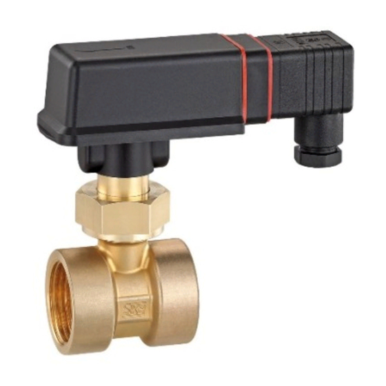
Produktabbildungen beispielhaft / Examples of product illustrations /
Illustrations du produit à titre d'exemple
Publicité
Chapitres
Table des Matières

Manuels Connexes pour SIKA VH Série


Sommaire des Matières pour SIKA VH Série
- Page 1 Betriebsanleitung ..........Seite 2 - 17 Operating manual ..........page 18 - 33 Notice d'utilisation ..........page 34 - 51 Strömungsschalter Baureihe VH / VK Flow switches series VH / VK Contrôleurs de débit série VH / VK Produktabbildungen beispielhaft / Examples of product illustrations / Illustrations du produit à...
-
Page 2: Table Des Matières
Weitergabe sowie Vervielfältigung dieser Betriebsanleitung, Verwertung und Mitteilung seines Inhalts sind verboten, soweit nicht ausdrücklich gestattet. Zuwiderhandlungen verpflichten zu Schadenersatz. Alle Rechte für den Fall der Patent-, Gebrauchsmuster- oder Geschmacksmustereintragung vorbehal- ten. - 2 - © SIKA • Ea3000_FlowSwitch • 03/2021... -
Page 3: Hinweise Zur Betriebsanleitung
WICHTIG Nichtbeachtung kann Sach- und Umweltschäden zur Folge haben. Sollten Sie Probleme oder Fragen haben, wenden Sie sich an Ihren Lieferanten oder direkt SIKA Dr. Siebert & Kühn GmbH & Co. KG Struthweg 7–9 34260 Kaufungen / Germany +49 5605 803-0 ... -
Page 4: Sicherheitshinweise
Lesen Sie die Betriebsanleitung sorgfältig durch. Befolgen Sie alle Anweisungen und Hin- weise, um Personen- oder Sachschäden zu vermeiden. Bestimmungsgemäße Verwendung Die SIKA-Strömungsschalter der Baureihen VH / VK dürfen nur zur Minimum- bzw. zur Maximumüberwachung von Flüssigkeitsströmungen verwendet werden. WARNUNG Die Strömungsschalter der Baureihen VH / VK sind keine Sicherheitsbauteile im... -
Page 5: Einbau
VH / VK Einbau Die Strömungsschalter für den Einsatz im Ex-Bereich besitzen an der letzten Stelle der Arti- kelnummer ( Typenschild) ein "X". Sie sind einer Zündgefahrenbewertung entsprechend DIN EN 13463-1 bzw. DIN EN ISO 80079-36 unterzogen worden und besitzen keine eigenen potentiellen Zündquellen. -
Page 6: Rohrstück
Rohrleitung „aufrecht stehend“ ist. Bauen Sie den Strömungsschalter nur senkrecht stehend ein und be- achten Sie die Abweichung von max. 45°. Kontaktieren Sie bitte SIKA bei abweichenden Einbaulagen. Beachten Sie, dass der Pfeil auf dem Strömungsschalter in Durchfluss- richtung zeigt und parallel mit der Rohrleitungsachse läuft. -
Page 7: Direkteinbau
VH / VK Einbau 2.2 Direkteinbau Das Paddel darf nicht an der Rohrwandung anstoßen und muss sich frei bewegen können . Das Paddel darf nicht an der Innenseite des Doms anstoßen Beachten Sie das Einbauhöhenmaß. Kürzen des Paddels (nur VHS06, VHS09, VK306, VK309) ... -
Page 8: Elektrischer Anschluss
DIN EN 175301-803-A oder mit fester Anschlussleitung ausgerüstet. Zur Vermeidung von elektrostatischer Aufladung müssen Sie die Geräte über den Steckver- binder bzw. über die feste Anschlussleitung an den Potentialausgleich anschließen. - 8 - © SIKA • Ea3000_FlowSwitch • 03/2021... -
Page 9: Steckverbinder Din En 175301-803-A
VH / VK Elektrischer Anschluss 3.1 Steckverbinder DIN EN 175301-803-A WICHTIG • Zur Gewährleistung der Schutzart IP 65 nach EN 60529 muss die verwendete Anschlussleitung einen Manteldurchmesser von 4,5 bis 10 mm aufweisen. • Ferner müssen Sie darauf achten, dass alle Dichtungen ... -
Page 10: Rundstecker M12X1 (4-Pin)
Typ VH3...X Typ VH3... Abb. 9a Abb. 9b Abb. 10 * Zur Vermeidung von elektrostatischer Aufladung müssen Sie die Geräte des Typs VH3...X über die feste Anschlussleitung an den Potentialausgleich anschließen. - 10 - © SIKA • Ea3000_FlowSwitch • 03/2021... -
Page 11: Schalteinheit Einstellen (Optional)
VH / VK Schalteinheit einstellen (optional) Schalteinheit einstellen (optional) Standardkontakt Der Strömungsschalter kann als Arbeitskontakt (Schließer) oder als Ruhekontakt (Öffner) be- trieben werden. Die nachstehende Tabelle dient der Erläuterung der beiden Kontaktarten: Kontaktart Einstellung Durchfluss Elektrischer Kontakt Arbeitskontakt Roter Pfeil Ansteigend Schließend (ohne Strömung geöffnet) - Page 12 VK3 Sichern Sie ggf. die Arretierungsschraube der Schalt- einheit mit Lack/Schraubensicherungslack nach indivi- dueller Einstellung des Schaltpunktes. Schaltkopf schließen (nur VHS, VKS) Schließen Sie den Deckel bis zur Einrastung. - 12 - © SIKA • Ea3000_FlowSwitch • 03/2021...
-
Page 13: Wartung Und Rücksendung
Das Gerät besteht aus unterschiedlichen Werkstoffen. Es darf nicht zusammen mit Hausmüll entsorgt werden. Führen Sie den Strömungsschalter der lokalen Wiederverwertung zu oder schicken Sie den Strömungsschalter an Ihren Lieferanten bzw. SIKA zurück. * WEEE-Reg.-Nr.: DE 25976360 Technische Änderungen vorbehalten - 13 -... -
Page 14: Technische Daten
Max. 3 VA, 3 W Schutzart IP 65 (DIN EN 60529) Schutzklasse Klasse II Klasse I (DIN EN 60730-1) *1 Schaltspannung 24...230 V AC / DC ±20 %, Umgebungstemperatur -20...70 °C. - 14 - © SIKA • Ea3000_FlowSwitch • 03/2021... - Page 15 VH / VK Technische Daten Prozessgrößen Nenndruck PN 10 Medium 0…20 °C (PN 10 / PVC- -25…100 °C (nicht gefrierend) Rohrstück) 0…60 °C (PN 2,5 / PVC- Rohrstück) Umgebung 0…60 °C (PVC-Rohrstück) (nicht<4 °C lagern) -25…70 °C (VK3) Dauertemperaturbelastung der Max.
-
Page 16: Medienberührende Werkstoffe
PPE+PS Noryl PVDF 30 % glasfaserverstärkt Niet Messing CW508L Edelstahl 1.4303 Achse Edelstahl 1.4571 Magnet Hartferrit Dichtung NBR (Messing-Rohrstück) EPDM (PVC-Rohrstück) *1 Nur VK325, VK340, VK350, VKS25, VKS40, VKS50 und VKS350. - 16 - © SIKA • Ea3000_FlowSwitch • 03/2021... -
Page 17: Zulassungen
VH / VK EG-Konformitätserklärung VHS06 / VHS09 VK306 / VK309 Körper Messing CW614N PPE+PS Noryl 30 % glasfaserverstärkt VHS06 / VK309: Kunststoffpaddel PPE+PS Noryl 30 % glasfaserverstärkt / Edelstahl Edelstahlpaddel Edelstahl 1.4310 / Messing VHS09 / VK309: Paddel / Hülse PPE+PS Noryl 30 % glasfaserverstärkt / Edelstahl Prozessan-... - Page 18 Offenders will be held liable for the payment of damages. All rights reserved in the event of the grant of a patent, utility model or design. - 18 - © SIKA • Ea3000_FlowSwitch • 03/2021...
-
Page 19: About This Operating Manual
Failure to do so may result in damage to property and the environment. If you have any problems or questions, please contact your supplier or contact us directly at: SIKA Dr. Siebert & Kühn GmbH & Co. KG Struthweg 7–9 34260 Kaufungen / Germany ... -
Page 20: Safety Instructions
Read through the operating manual carefully. Follow all instructions and notices to prevent injury or damage to property. Intended use SIKA flow switches of the VH / VK series must only be used for minimum or maximum monitoring of liquid flows. WARNING The flow switches of the VH / VK series are no safety components in accordance with Directive 2006/42/EC (Machine Directive). -
Page 21: Installation
VH / VK Installation The flow switches for application in explosion-hazardous area have an "X” at the end of the article number ( type plate). They have been subjected to an ignition hazard assessment according to DIN EN 13463-1 resp. DIN EN ISO 80079-36 and do not have potential sources of ignition. -
Page 22: Pipe Section
“upright”. Only mount the flow switch in an upright position and take into account the deviation of a maximal 45°. Please contact SIKA, when the mount- ing position differs. Take into account that the arrow on the flow switch points into the flow direction and runs parallel to the pipe axis. -
Page 23: Insertion Installation
VH / VK Installation 2.2 Insertion installation The paddle must not hit the pipe wall must be able to move freely The paddle must not touch the inside of the dome Observe the installation height dimensions. Shortening of paddle (only VHS06, VHS09, VK306, VK309) ... -
Page 24: Electrical Connection
The flow switch type VH...X is equipped with either a plug connector EN 175301-803-A or a permanent connecting cable. To prevent electrostatic charging the devices have to be connected to the equipotential bonding via the elbow connector plug or the fixed connecting cable. - 24 - © SIKA • Ea3000_FlowSwitch • 03/2021... -
Page 25: Plug Connector En 175301-803-A
VH / VK Electrical connection 3.1 Plug connector EN 175301-803-A IMPORTANT • To guarantee the type of protection IP 65 according to EN 60529, the connect- ing cable has to have a sheathing diameter of between 4.5 and 10 mm. •... -
Page 26: Sensor Plug M12X1 (4-Pin)
Type VH3...X Type VH3... Fig. 9a Fig. 9b Fig. 10 * To prevent electrostatic charging the VH3…X devices have to be connected to the equipotential bonding via the fixed connecting cable. - 26 - © SIKA • Ea3000_FlowSwitch • 03/2021... -
Page 27: Adjusting The Switching Unit (Optional)
VH / VK Adjusting the switching unit (optional) Adjusting the switching unit (optional) Standard contact The flow switch can be operated as normally open contact or as normally closed contact. The following table explains the two types of contact: Contact Setting Flow Electric contact... - Page 28 If applicable, secure the locking screw of the switching unit using varnish / thread-locking fluid after individually setting the setpoint. Closing the switch head (only VHS, VKS) Close the lid until it clicks into place. - 28 - © SIKA • Ea3000_FlowSwitch • 03/2021...
-
Page 29: Maintenance And Return Shipment
The device consists of various different materials. It must not be disposed of with household waste. Take the flow switch to your local recycling plant send the flow switch back to your supplier or to SIKA. * WEEE reg. no.: DE 25976360 Technical changes reserved... -
Page 30: Technical Data
Max. 3 VA, 3 W Degree of protection IP 65 (EN 60529) Protection class Class II Class I (EN 60730-1) *1 Switching voltages 24 V...230 V AC/DC ±20 %, ambient temperature -20...70 °C. - 30 - © SIKA • Ea3000_FlowSwitch • 03/2021... - Page 31 VH / VK Technical Data Type Process variables Nominal pressure PN 10 Medium 0…20 °C (PN 10 / PVC pipe -25…100 °C (non-freezing) section) 0…60 °C (PN 2,5 / PVC pipe section) Ambient 0…60 °C (PVC pipe section) (do not store <4 °C) -25…70 °C (VK3) Max.
-
Page 32: Materials In Contact With Medium
Rivet Brass CW508L Stainless steel 1.4303 Stainless steel 1.4571 Magnet Hard ferrite Gasket NBR (Brass pipe section) EPDM (PVC pipe section) *1 Only VK325, VK340, VK350, VKS25, VKS40, VKS50 and VKS350. - 32 - © SIKA • Ea3000_FlowSwitch • 03/2021... -
Page 33: Approvals
VH / VK EC Declaration of Conformity Type VHS06 / VHS09 VK306 / VK309 Body Brass CW614N PPE+PS Noryl 30 % glass fibre reinforced VHS06 / VK309: Plastic paddle PPE+PS Noryl 30 % glass fibre reinforced / Stainless steel Stainless steel Stainless steel 1.4310 / Brass paddle VHS09 / VK309:... - Page 34 Tout manquement à cette règle est illi- cite et expose son auteur au versement de dommages et intérêts. Tous droits réservés pour le cas de la délivrance d’un brevet, d’un modèle d’utilité ou d’un modèle de présentation. - 34 - © SIKA • Ea3000_FlowSwitch • 03/2021...
-
Page 35: Remarques Sur La Notice D'utilisation
Tout non-respect peut engendrer des dommages matériels et sur l’environne- ment. Si vous avez des problèmes ou des questions, adressez-vous à votre fournisseur ou directe- ment à : SIKA Dr. Siebert & Kühn GmbH & Co. KG Struthweg 7–9 34260 Kaufungen / Germany +49 5605 803-0 ... -
Page 36: Consignes De Sécurité
Lisez attentivement la notice d’utilisation. Respectez toutes les consignes et indications afin d’éviter tout dommage corporel ou matériel. Utilisation conforme Les contrôleurs de débit de SIKA des séries VH / VK sont destinés au contrôle des minima et maxima du débit de liquides. AVERTISSEMENT Les contrôleurs de débit des séries VH / VK ne sont aucuns composants de sécu-... -
Page 37: Installation
VH / VK Installation Le dernier caractère de la référence des contrôleurs de débit conçus pour le domaine Ex est un « X » ( plaque signalétique). Les contrôleurs ont été soumis à une évaluation du risque d’allumage selon DIN EN 13463-1 resp. DIN EN ISO 80079-36. Ils ne représentent pas en eux-mêmes une source d’allumage potentielle. -
Page 38: Té De Montage
Tournez le raccord union sur le filetage (sans le serrer). Orientez le contrôleur de débit dans le sens du débit. Serrez le raccord union en plastique avec 7…8 Nm ou le raccord union en métal avec 25…30 Nm. - 38 - © SIKA • Ea3000_FlowSwitch • 03/2021... -
Page 39: Installation Directe
VH / VK Installation 2.2 Installation directe La palette ne doit pas toucher la paroi du tuyau et doit pouvoir se déplacer libre- ment La palette ne doit pas toucher l’intérieur du dôme Respectez la dimension de la hauteur d’ins- tallation. -
Page 40: Raccordement Électrique
175301-803-A soit d’un câble de connexion fixe. Afin d’éviter les charges électrostatiques, il faut connecter les appareils à la compensa- tion de potentiel par le raccord électrique ou le câble de connexion fixe. - 40 - © SIKA • Ea3000_FlowSwitch • 03/2021... -
Page 41: Raccord Électrique En 175301-803-A
VH / VK Raccordement électrique 3.1 Raccord électrique EN 175301-803-A IMPORTANT • Afin de garantir le degré de protection IP 65 selon EN 60529, le diamètre ex- terne de la gaine du câble de connexion utilisé doit être compris entre 4,5 et 10 mm. -
Page 42: Connecteur À Broches M12X1 (4 Broches)
VH3...X type VH3... Fig. 9a Fig. 9b Fig. 10 * Afin d’éviter les charges électrostatiques, vous devez connecter les appareils du type VH3...X à la liaison équipotentielle par le raccord électrique. - 42 - © SIKA • Ea3000_FlowSwitch • 03/2021... -
Page 43: Régler L'unité De Commutation (Facultatif)
VH / VK Régler l’unité de commutation (facultatif) Régler l’unité de commutation (facultatif) Contact standard Le contrôleur de débit peut être exploité comme contact de travail (contact à fermeture) ou comme contact de repos (contact à ouverture). Le tableau suivant explique les deux types de contact : Type de contact Réglage... - Page 44 Fermer la tête de commutation (uniquement VHS, VKS) Fermez le couvercle, jusqu’à ce qu’il s’encoche. - 44 - © SIKA • Ea3000_FlowSwitch • 03/2021...
-
Page 45: Entretien Et Retour Au Fabricant
Emportez le commutateur de débit à votre centre local de recyclage renvoyez le commutateur de débit à votre fournisseur ou à SIKA. * Inscription au registre DEEE : DE 25976360 Sous réserve de modifications techniques... -
Page 46: Données Techniques
Degré de protection IP 65 (EN 60529) Classe de protection Classe II Classe I (EN 60730-1) *1 Tension du contact 24...230 V AC / DC ±20 %, température ambiante -20...70 °C. - 46 - © SIKA • Ea3000_FlowSwitch • 03/2021... - Page 47 VH / VK Données techniques Type Variables process Pression nominale PN 10 Fluide 0…20 °C (PN 10 / té de mon- -25…100 °C (ne doit pas geler) tage PVC) 0…60 °C (PN 2,5 / té de mon- tage PVC) Environnement 0…60 °C (té...
- Page 48 (EN 60730-1) S’applique au contrôleur de débit de type VH...X L’énergie d’allumage de l’atmosphère potentiellement explosive ne doit pas être inférieure à 60 µJ. Les inductions et capacités internes effectives sont négligeables. - 48 - © SIKA • Ea3000_FlowSwitch • 03/2021...
-
Page 49: Matériaux En Contact Avec Le Fluide
VH / VK Données techniques 7.1 Matériaux en contact avec le fluide Type VHS / VH3 VHS / VH3 (Version en laiton) (Version en acier inoxy- dable) Corps Laiton CW614N Acier inoxydable 1.4571 PPE+PS Noryl 30 % renforcé de fibres de verre Palette Laiton CW614N... -
Page 50: Homologations
Les contrôleurs de débit des séries VHS M, VHS X, VKS M, VH3..M, VK3..M, VH3.., VH3..X et VKX.. sont conformes aux directives 2014/35/UE et 2011/65/UE. Les contrôleurs de débit sont conformes aux règles techniques DIN EN 60204-1:2019 et DIN EN IEC 63000:2019. - 50 - © SIKA • Ea3000_FlowSwitch • 03/2021... - Page 51 VH / VK Sous réserve de modifications techniques - 51 -...
- Page 52 SIKA Dr. Siebert & Kühn GmbH & Co. KG Struthweg 7–9 34260 Kaufungen / Germany +49 5605 803-0 +49 5605 803-555 info@sika.net www.sika.net © SIKA • Ea3000_FlowSwitch • 03/2021...