Table des Matières

Publicité

Les langues disponibles

Les langues disponibles

Liens rapides

Betriebsanleitung
Betriebsanleitung .................................................... Seite 1 - 16
Operating manual .................................................. page 17 - 32
Notice d'utilisation ................................................. page 33 - 48
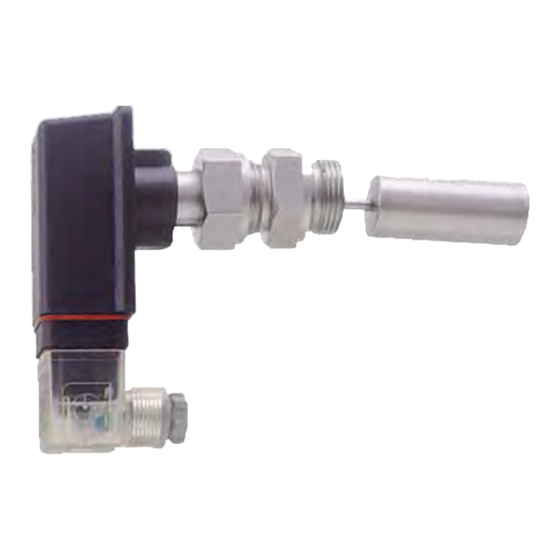
Niveauwächter
Baureihen VH... / VK...
Bewahren Sie diese Betriebsanleitung zum Nachschlagen auf.
Geben Sie diese Betriebsanleitung bei der Veräußerung des Gerätes mit.
(Original)

Publicité

Table des Matières
loading

Sommaire des Matières pour SIKA VH

  • Page 1 Betriebsanleitung ............ Seite 1 - 16 Operating manual ..........page 17 - 32 Notice d'utilisation ..........page 33 - 48 Niveauwächter Baureihen VH... / VK... Bewahren Sie diese Betriebsanleitung zum Nachschlagen auf. Geben Sie diese Betriebsanleitung bei der Veräußerung des Gerätes mit.
  • Page 2: Table Des Matières

    Haftungsausschluss ....................5 Sicherheitshinweise ...................... 6 Qualifiziertes Personal ....................6 Spezielle Sicherheitshinweise ..................6 Zusätzlich gilt für Niveauwächter VH...X ..............7 Materialspezifikationen der benetzten Bauteile ............7 Einbau des Niveauwächters ..................8 Allgemeine Einbauhinweise ..................8 Elektrischer Anschluss ....................9 Allgemeine Hinweise zum elektrischen Anschluss ...........
  • Page 3: Hinweise Zur Betriebsanleitung

    VH... / VK... Hinweise zur Betriebsanleitung Hinweise zur Betriebsanleitung • Die Betriebsanleitung richtet sich an Facharbeiter und angelernte Arbeitskräfte. • Lesen Sie vor jedem Arbeitsschritt die dazugehörigen Hinweise sorgfältig durch und halten Sie die vorgegebene Reihenfolge ein. • Lesen Sie den Abschnitt "Sicherheitshinweise" besonders aufmerksam durch.
  • Page 4: Gerätebeschreibung

    Die SIKA-Niveauwächter sind zur Minimum- bzw. zur Maximumüberwachung von Flüssig- keitsfüllständen vorgesehen. WARNUNG! Kein Sicherheitsbauteil! Die Niveauwächter der Baureihe VH... / VK... sind keine Sicherheitsbauteile im Sinne der Richtlinie 2006/42/EG (Maschinenrichtlinie).  Verwenden Sie den VH... / VK... niemals als Sicherheitsbauteil.
  • Page 5: Niveauwächterausführung Vh

    Stromkreis im Sinne der DIN EN 60079-11: 2007 dar. Die wirk- samen inneren Induktivitäten und Kapazitäten sind vernachlässigbar klein. Die Niveauwächter der Baureihe VH...X sind für den Einsatz in Bereichen vorgesehen, in de- nen eine explosionsfähige Atmosphäre vorhanden ist. Die Zündenergie der explosionsfähigen Atmosphäre darf 60 µJ nicht unterschreiten.
  • Page 6: Sicherheitshinweise

    Sicherheitshinweise VH... / VK... Sicherheitshinweise Bevor Sie den VH... / VK... installieren, lesen Sie diese Betriebsanleitung sorgfältig durch. Werden die darin enthaltenen Anweisungen, insbesondere die Sicherheitshinwei- se nicht beachtet, können Gefahren für Mensch, Geräte und Anlagen die Folge sein. Die Niveauwächter entsprechen dem aktuellen Stand der Technik. Dies betrifft die Schalt- punktgenauigkeit, die Funktionsweise und den sicheren Betrieb der Geräte.
  • Page 7: Zusätzlich Gilt Für Niveauwächter Vh

    Typenschilder oder sonstige Hinweise auf dem Gerät dürfen weder entfernt noch un- kenntlich gemacht werden, da sonst jegliche Garantie und Herstellerverantwortung er- lischt. 2.3 Zusätzlich gilt für Niveauwächter VH...X Es dürfen nur Medien mit einer minimalen Zündtemperatur >135 °C und einer Zündener- gie >60µJ mit dem Niveauwächter in Berührung kommen.
  • Page 8: Einbau Des Niveauwächters

    Niveauwächters lösen Sie die Überwurfmutter (SW32 oder Rändel), richten den Niveau- wächter aus und ziehen die Mutter, unter Gegenhalten am Einschraubzapfen, wieder an.  Die Überwurfmutter G¾ aus Messing oder Edelstahl (Ausführung VH..) müssen Sie mit einem Anzugsmo- ment von 25…30 Nm anziehen.  Die Überwurfmutter aus Kunststoff (Ausführung VK..) muss mit einem Anzugsmoment von 7…8 Nm angezo-...
  • Page 9: Elektrischer Anschluss

    Der elektrische Anschluss des VH... / VK... darf nur von einer Elektrofachkraft vorge- nommen werden.  Schalten Sie die elektrische Anlage spannungsfrei, bevor Sie den VH... / VK... anschließen. VORSICHT! Zerstörung oder Beschädigung des Reedkontaktes! Die auf dem Typenschild angegebene max. Kontaktbelastungen gelten nur für rein ohm- sche Lasten und dürfen auf keinem Fall überschritten werden.
  • Page 10: Sensorstecker M12X1 (4-Polig)

    Potentialausgleich* nicht belegt Abb. 11 *) Zur Vermeidung von elektrostatischer Aufladung müssen Sie die Geräte der Ausführung VH...X über den Winkelsteckverbinder an den Potenzialausgleich anschließen. 5.3 Sensorstecker M12x1 (4-polig)  Zum Anschluss verwenden Sie nur geeignete Kupplungsdosen M12x1. Diese sind mit di- rekt angespritzter Leitung oder zum Selbstkonfektionieren als Zubehör lieferbar.
  • Page 11: Verstellen Der Schalteinheit

    VH... / VK... Verstellen der Schalteinheit Verstellen der Schalteinheit Wichtige Hinweise! Bei kundenseitig gewünschter Schaltpunktfesteinstellung ab Werk entfällt das Verstellen der Schalteinheit. Wenn keine Pfeile auf der Schalteinheit sind, ist ein Verstellen der Kontaktart oder des Schaltpunktes nicht zulässig. 6.1 Kontaktart Die Schalteinheit des Niveauwächters ermöglicht zwei verschiedene Kontaktarten:...
  • Page 12: Niveauwächterausführung Vh60

     Nach der Einstellung des Schaltpunktes empfehlen wir die Arretierungsschraube mit Lack oder Schraubensicherungslack zu sichern. Abb. 18 Bei kundenseitig gewünschter Schaltpunktfesteinstel- lung ab Werk entfällt das Verstellen der Schalteinheit. - 12 - © SIKA • Ea1300_LevelSwitch • 04/2016...
  • Page 13: Wartung Und Reinigung

     Bauen Sie den VH... / VK... mit passenden Werkzeugen aus. Entsorgung: KEIN HAUSMÜLL! Der VH... / VK... besteht aus unterschiedlichen Werkstoffen ( § 3). Er darf nicht zu- sammen mit Hausmüll entsorgt werden.  Führen Sie den VH... / VK... der lokalen Wieder-...
  • Page 14: Technische Daten

    Die wirksamen inneren Induktivitäten und Kapazitäten sind vernachlässigbar klein. 10 Zulassungen Die SIKA-Niveauwächter sind vom TÜV Rheinland bauartgeprüft, Prüfzeichen R 60077518 vom 04.12.2012 (gilt nicht für Ausführung mit Sensorstecker M12x1 und nicht für VH...X). - 14 - © SIKA • Ea1300_LevelSwitch • 04/2016...
  • Page 15: Eg-Konformitätserklärung

    VH... / VK... EG-Konformitätserklärung 11 EG-Konformitätserklärung Technische Änderungen vorbehalten - 15 -...
  • Page 16 VH... / VK... Mess- und Sensortechnik Durchflussmesstechnik Test- und Kalibriertechnik SIKA Dr. Siebert & Kühn GmbH & Co. KG Struthweg 7–9 D-34260 Kaufungen  Germany  +49 (0)5605 803-0  +49 (0)5605 803-54 info@sika.net  www.sika.net - 16 - © SIKA • Ea1300_LevelSwitch • 04/2016...
  • Page 17 Operating manual ..........page 17 - 32 Notice d'utilisation ..........page 33 - 48 Level Switches Series VH... / VK... Please keep this operating manual for future reference. If the device is resold, please provide the operating manual along with it.
  • Page 18 Exclusion of liability ....................21 Safety instructions ....................... 22 Qualified personnel ....................22 Special safety instructions ..................22 Additional information for the VH...X level switch ............ 23 Material specifications of wetted components ............23 Level switch installation ....................24 General installation instructions ................24 Electrical connection ....................
  • Page 19: About This Operating Manual

    VH... / VK... About this operating manual About this operating manual • The operating manual is aimed at specialists and semi-skilled personnel. • Before each step, read through the relevant advice carefully and keep to the specified order. • Thoroughly read and understand the information in the section "Safety instructions".
  • Page 20: Device Description

    SIKA level switches are designed for the monitoring of minimum or maximum liquid filling levels. WARNING! No safety component! The level switches of the series VH... / VK... are not safety components in accordance with Directive 2006/42/EC (Machine Directive).  Never use the VH... / VK... as a safety component.
  • Page 21: Level Switch Version Vh

    DIN EN 60079-11: 2007. The effective internal inductances and capacities are negligibly small. The level switches series VH...X are designed for application in potentially explosive atmos- phere. The ignition energy of the explosive atmosphere should not fall below 60 µJ.
  • Page 22: Safety Instructions

    VH... / VK... Safety instructions Before you install the VH... / VK..., read through this operating manual carefully. If the in- structions contained within it are not followed, in particular the safety guidelines, this could result in danger for people, the environment, and the device and the system it is connected to.
  • Page 23: Additional Information For The Vh

    2.3 Additional information for the VH...X level switch The level switch should only be used for media with a minimum ignition temperature of >135 °C and ignition energy of >60 µJ.
  • Page 24: Level Switch Installation

    (size 32 or knurled), align the level switch and retighten the nut.  Tighten the brass or stainless steel union nut ¾” (VH.. version) with a tightening torque of 25…30 Nm.  Tighten the plastic union nut (VK.. version) with a tight- ening torque of 7…8 Nm.
  • Page 25: Electrical Connection

     Pay attention to § 1.1.2 Reed contact - Switching of inductive or capacitive loads. Additional information for the VH...X level switch  The VH...X level switch can be connected as a simple electrical instrument in a certified intrinsically safe circuit.
  • Page 26: Sensor Plug M12X1 (4-Pole)

    Equipotential bonding* not occupied Fig. 11 *) To prevent electrostatic charging the VH…X devices have to be connected to the equipotential bonding via the elbow plug connector. 5.3 Sensor plug M12x1 (4-pole)  Only use suitable M12x1 coupling sockets for the connection. These are supplied as ac- cessories with either a directly moulded cable or for self-assembly.
  • Page 27: Adjusting The Switching Unit

    Unless otherwise requested by the customer, the switching is factory set as a normally open contact. 6.2 Level switch version VH...X WARNING! LOSS OF EXPLOSION PROTECTION! No explosion protection when adjusting the type of contact or the switching point.
  • Page 28: Level Switch Version Vh60

    Adjustment of the switching unit is not required if a de- Fig. 18 sired ex works switching point setting has been agreed with the customer. - 28 - © SIKA • Ea1300_LevelSwitch • 04/2016...
  • Page 29: Maintenance And Cleaning

    When opening the device, critical parts or components can be damaged.  Never open the device. Cleaning: Clean the VH... / VK... with a dry or slightly damp lint-free cloth. Do not use sharp objects or aggressive agents for cleaning Decommissioning and Disposal CAUTION! Risk of injury! Never remove a level switch or its body from a system under pressure.
  • Page 30: Technical Data

    10 Approvals SIKA level switches are type approved by TÜV Rheinland, certification no. R 60077518, issued on 04.12.2012 (does not apply for version with M12x1 sensor plug and not for VH…X). - 30 - © SIKA • Ea1300_LevelSwitch • 04/2016...
  • Page 31: Ec Declaration Of Conformity

    VH... / VK... EC declaration of conformity 11 EC declaration of conformity Technical changes reserved - 31 -...
  • Page 32 VH... / VK... Sensors and Measuring Instruments Flow Measuring Instruments Test and Calibration Instruments SIKA Dr. Siebert & Kühn GmbH & Co. KG Struthweg 7–9 D-34260 Kaufungen  Germany  +49 (0)5605 803-0  +49 (0)5605 803-54 info@sika.net  www.sika.net - 32 - ©...
  • Page 33: Contrôleur De Niveau

    Betriebsanleitung ............ Seite 1 - 16 Operating manual ..........page 17 - 32 Notice d'utilisation ..........page 33 - 48 Contrôleur de niveau Séries VH... / VK... Conservez cette notice d'utilisation pour vous y reporter. Joignez cette notice d'utilisation à la vente de l'appareil.
  • Page 34 Consignes de sécurité ....................38 Personnel qualifié ..................... 38 Instructions spéciales de sécurité : ................38 Conditions supplémentaires pour le contrôleur de niveau VH...X ......39 Spécification des matériaux des composants mouillés ..........39 Montage du contrôleur de niveau ................40 Généralités ........................
  • Page 35: Indications Sur La Notice D'utilisation

    VH... / VK... Indications sur la notice d'utilisation Indications sur la notice d'utilisation • La notice d'utilisation est destinée à un personnel formé et spécialisé. • Avant chaque étape de travail, lisez attentivement les indications correspondantes dans l'ordre indiqué. •...
  • Page 36: Description De L'appareil

    AVERTISSEMENT ! Aucun composant de sécurité ! Les contrôleurs de niveau VH... / VK... ne sont pas des composants de sécurité aux termes de la directive 2006/42/CE (directive sur les machines).  N'utilisez jamais un VH... / VK... comme composant de sécurité.
  • Page 37: Modèle De Contrôleur De Niveau Vh

    Tenir compte de la séparation des zones : Les contrôleurs de niveau de la série VH...X sont conçu tel que l’intérieur de la conduite, où se trouve le flotteur, peut être soumis en permanence, pendant une longue période de temps ou souvent à...
  • Page 38: Consignes De Sécurité

    Les VH... / VK... correspondent à l'état actuel de la technique. Cela concerne la précision du point de commutation, le mode de fonctionnement et la sécurité du fonctionnement de l'appareil.
  • Page 39: Conditions Supplémentaires Pour Le Contrôleur De Niveau Vh

    Les plaques signalétiques ou autres indications sur l’appareil ne doivent être ni enlevées ni rendues illisibles, sinon la garantie et la responsabilité du fabricant expirent. 2.3 Conditions supplémentaires pour le contrôleur de niveau VH...X Le contrôleur de niveau ne doit être mis en contact qu’avec des milieux possédant une température d’allumage minimale >135 °C et une énergie d’allumage >60 µJ.
  • Page 40: Montage Du Contrôleur De Niveau

    32 ou molettes), ajuster le contrôleur de niveau et resserrer l’écrou.  Les écrous d’accouplement en filetage G¾ en laiton ou en acier spécial (Modèle VH..) doivent être serrés avec un moment de serrage compris entre 25 et 30 Nm.
  • Page 41: Branchement Électrique

     Prenez note § 1.1.2 Contact reed - Commuter de charges inductives ou capacitaires. Conditions supplémentaires pour le contrôleur de niveau VH...X  Le modèle de contrôleur de niveau VH...X peut être branché, comme du matériel élec- trique simple, sur un circuit électrique à sécurité intrinsèque certifié.
  • Page 42: Prise Du Capteur M12X1 (À 4 Pôles)

    Reed vert compensation /jaune de potentiel* Fig. 13 *) Afin d’éviter les charges électrostatiques, vous devez connecter les appareils à la compensation de potentiel par le câble de connexion fixe. - 42 - © SIKA • Ea1300_LevelSwitch • 04/2016...
  • Page 43: Régler L'unité De Commutation

    Si le client ne spécifie pas, l’unité de commutation est réglée en usine tel un contact de travail. 6.2 Modèle de contrôleur de niveau VH...X AVERTISSEMENT! PERTE DE LA PROTECTION CONTRE LES EXPLOSIONS! Pas de protection contre les explosions en cas de modification du type de contact ou du point de commutation.
  • Page 44: Modèle De Contrôleur De Niveau Vh60

    Fig. 18 Si le client souhaite que le réglage fin du point de commutation soit effectué en usine, le ré- glagede l’unité de commutation n’est pas à faire. - 44 - © SIKA • Ea1300_LevelSwitch • 04/2016...
  • Page 45: Entretien Et Nettoyage

    Élimination : PAS DE DECHET MENAGER ! Le VH... / VK... se compose de différents matériaux ( § 3). Il ne peut pas être jetée en- semble avec les déchets ménagers.  Emportez le VH... / VK... à votre centre local de re- cyclage ...
  • Page 46: Données Techniques

    Les inductions et capacités internes effectives sont négligeables. 10 Homologations Les modèles de contrôleur de niveau SIKA sont homologués par le contrôle technique TÜV de Rhénanie, estampille de contrôle R 60077518 du 04.12.2012 (ne s'applique pas au modèle avec connec- teur de capteur M12x1).
  • Page 47: Déclaration De Conformité Ue

    VH... / VK... Déclaration de conformité UE 11 Déclaration de conformité UE Sous réserve de modifications techniques - 47 -...
  • Page 48 Flow Measuring Instruments Instruments de mesure de débit Test und Kalibriertechnik Test and Calibration Instruments Instruments de test et matériels de calibration SIKA Dr. Siebert & Kühn GmbH & Co. KG Struthweg 7–9 D-34260 Kaufungen  Germany  +49 (0)5605 803-0 ...

Table des Matières