SIKA VH Série Notice D'utilisation
Masquer les pouces
Voir aussi pour VH Série:
- Notice d'utilisation (28 pages) ,
- Notice d'utilisation (52 pages) ,
- Notice d'utilisation (48 pages)
Table des Matières
Publicité
Les langues disponibles
Les langues disponibles
Liens rapides
Betriebsanleitung
Betriebsanleitung ....................................................Seite 1 - 20
Operating manual .................................................. page 21 - 40
Notice d'utilisation................................................. page 41 - 60
Strömungsschalter
Baureihen VH... / VK...
Bewahren Sie diese Betriebsanleitung zum Nachschlagen auf.
Geben Sie diese Betriebsanleitung bei der Veräußerung des Gerätes mit.
(Original)
Publicité
Chapitres
Table des Matières

Manuels Connexes pour SIKA VH Série


Sommaire des Matières pour SIKA VH Série
- Page 1 Betriebsanleitung (Original) Betriebsanleitung ............Seite 1 - 20 Operating manual ..........page 21 - 40 Notice d'utilisation..........page 41 - 60 Strömungsschalter Baureihen VH... / VK... Bewahren Sie diese Betriebsanleitung zum Nachschlagen auf. Geben Sie diese Betriebsanleitung bei der Veräußerung des Gerätes mit.
-
Page 2: Table Des Matières
Weitergabe sowie Vervielfältigung dieser Betriebsanleitung, Verwertung und Mitteilung seines Inhalts sind verboten, soweit nicht ausdrücklich gestattet. Zuwiderhandlungen verpflichten zu Schadenersatz. Alle Rechte für den Fall der Patent-, Gebrauchsmuster- oder Geschmacksmustereintragung vorbe- halten. - 2 - © SIKA • Ea3000_FlowSwitch • 02/2014... -
Page 3: Hinweise Zur Betriebsanleitung
Dr. Siebert & Kühn GmbH & Co. KG Struthweg 7-9 • D - 34260 Kaufungen 05605-803 0 • 05605-803 54 info@sika.net • www.sika.net Verwendete Gefahrenzeichen und Symbole: GEFAHR! Lebensgefahr durch elektrischen Strom! Dieses Zeichen kennzeichnet Gefahren, die zu schweren gesundheitlichen Schäden oder zum Tode führen. -
Page 4: Gerätebeschreibung
Gerätebeschreibung VH... / VK... Gerätebeschreibung Die SIKA-Strömungsschalter sind zur Minimum- bzw. zur Maximumüberwachung von Flüs- sigkeitsströmungen vorgesehen. Bauteile Strömungsschalter: Funktionsprinzip: Der Strömungsschalter besteht aus einem Paddelsystem (1), an dessen oberen Ende sich ein Dauermagnet (2) befindet. Über diesem Magnet ist ein Reedkontakt (3), außerhalb der Strö- mung, platziert. -
Page 5: Strömungsschalterausführung Vh
VH... / VK... Gerätebeschreibung 1.1.1 Strömungsschalterausführung VH...X Die Strömungsschalter für den Einsatz im Ex-Bereich besitzen an der letzten Stelle der Arti- kelnummer ( Typenschild) ein "X". Sie sind einer Zündgefahrenbewertung entsprechend DIN EN 13463-1: 2002 und Berichtigung 1: 2003 unterzogen worden und besitzen keine eige- nen potentiellen Zündquellen. -
Page 6: Sicherheitshinweise
Werden die darin enthaltenen Anweisungen, insbesondere die Sicherheitshinwei- se nicht beachtet, können Gefahren für Mensch, Geräte und Anlagen die Folge sein. SIKA gewährt persönlich oder durch die entsprechende Literatur Hilfestellung für die An- wendung der Produkte, während der Kunde selber die Eignung der Produkte für die Anwen- dung festlegt. -
Page 7: Materialspezifikationen Der Medienberührten Bauteile
VH... / VK... Materialspezifikationen der medienberührten Bauteile Wenn das zu überwachende Medium sehr hohe Temperaturen besitzt, werden auch die Strömungsschalter bzw. deren Anschlussfittings extrem heiß. Vermeiden Sie Berührun- gen und stellen Sie keine temperaturempfindlichen Gegenstände in der Nähe ab. Schützen Sie den Strömungsschalter vor magnetischen Fremdfeldern in der unmittelba- ren Umgebung, da diese die Funktionsweise des Gerätes beeinträchtigen können. -
Page 8: Einbau Des Strömungsschalters
Anzugsmoment von 7...8 Nm angezogen werden Abb. 2b Zusätzlich gilt für die Strömungsschalterausführung VH...X Achten Sie bei der Wahl des Einsatzortes auf die angegebenen Grenzwerte ( § 9 "Technische Daten"). - 8 - © SIKA • Ea3000_FlowSwitch • 02/2014... -
Page 9: Strömungsschalter Mit Rohrstück
VH... / VK... Einbau des Strömungsschalters Beim Einbau und vor der Inbetriebnahme ist sicherzustellen, dass die mechanischen Pro- zessanschlüsse technisch dicht sind. Bei der Zoneneinteilung ist die Dichtheit der Verschraubungselemente zu berücksichti- gen. Entsprechend den Einsatzbedingungen kann es daher erforderlich sein, die Ver- schraubungselemente regelmäßig auf ihre Dichtheit hin zu überprüfen. - Page 10 Einbau in Muffen mit G½ Innengewinde: V- -06M... ab DN 50 - waagerechte Leitungen (Schalter aufrecht ste- V- -07M... ab DN 50 hend) - senkrechte Leitungen. Achtung: Beachten Sie unbedingt das Einbauhöhenmaß. - 10 - © SIKA • Ea3000_FlowSwitch • 02/2014...
-
Page 11: Elektrischer Anschluss
VH... / VK... Elektrischer Anschluss Elektrischer Anschluss 5.1 Allgemeine Hinweise zum elektrischen Anschluss GEFAHR! Lebensgefahr durch elektrischer Strom! Der elektrische Anschluss des VH... / VK... darf nur von einer Elektrofachkraft vorge- nommen werden. Schalten Sie die elektrische Anlage spannungsfrei, bevor Sie den VH... / VK... an- schließen. -
Page 12: Sensorstecker M12X1 (4-Polig)
5.3 Sensorstecker M12x1 (4-polig) Zum Anschluss verwenden Sie nur geeignete Kupplungsdosen M12x1. Diese sind mit di- rekt angespritzter Leitung oder zum Selbstkonfektionieren als Zubehör lieferbar. Pinbelegung des Anschlusssteckers: Abb. 14 - 12 - © SIKA • Ea3000_FlowSwitch • 02/2014... -
Page 13: Feste Anschlußleitung
VH... / VK... Verstellen der Schalteinheit 5.4 Feste Anschlussleitung Schließen Sie die Anschlussleitung nach dem Anschlussbild ( Abb. 15, Abb. 16) an: Standardkontakt: Wechselkontakt: Strömungsschalterausführung Strömungsschalterausführung nur Strömungsschalterausfüh- VH3.../VK3... VH3...X rung VH3... Abb. 15a Abb. 15b Abb. 16 * Zur Vermeidung von elektrostatischer Aufladung müssen Sie die Geräte der Ausführung VH3...X über die feste Anschlussleitung an den Potentialausgleich anschließen. -
Page 14: Strömungsschalterausführung Vhs
WICHTIG! Beachten Sie bei der Feinjustage! Bei den Ausführungen VHS06..., VHS07..., VKS06..., VKS07..., VK306... und VK307... ist ei- ne Feinjustage nicht möglich. Sie können nur die Kontaktart durch Verstellen der Schalteinheit ändern. - 14 - © SIKA • Ea3000_FlowSwitch • 02/2014... -
Page 15: Strömungsschalterausführung Vh3
VH... / VK... Wartung und Reinigung 6.4 Strömungsschalterausführung VH3... Zum Verstellen der Schalteinheit lösen Sie die Ar- Arbeitskontakt (roter Pfeil) hoher retierungsschraube (Innensechskant SW 1,5). Durchfluss geringer Verschieben Sie anschließend die Schalteinheit so Durchfluss weit, dass bei gewünschtem Arbeitskontakt, der Einstellbereich rote (... -
Page 16: Demontage Und Entsorgung
Hausmüll entsorgt werden. Führen Sie den VH... / VK... der lokalen Wieder- verwertung zu oder schicken Sie den VH... / VK... an Ihren Lieferanten bzw. SIKA zurück. - 16 - © SIKA • Ea3000_FlowSwitch • 02/2014... -
Page 17: Technische Daten
VH... / VK... Technische Daten Technische Daten Bei kundenspezifischen Ausführung können technische Daten gegenüber den Angaben die- ser Anleitung abweichen. Bitte beachten Sie die Angaben auf dem Typenschild. Strömungsschalterausführung VH... und VK... Baureihe VHS... VH3... VH3... VKS... VK3... VKS...K VK3...K Nenndruck PN 25 PN 10... -
Page 18: Maximaler Durchfluss Der Strömungsschalter
(Einbaulänge 24 mm) DN 100 DN 150 10 Zulassungen Die SIKA-Strömungsschalter sind vom TÜV Rheinland bauartgeprüft, Prüfzeichen R 60077518 vom 04.12.2012 (gilt nicht für Ausführung mit Sensorstecker M12x1 und nicht für VH...X). Referenz Nr. 1102336 - 18 - © SIKA • Ea3000_FlowSwitch • 02/2014... -
Page 19: Eg-Konformitätserklärung
VH... / VK... EG-Konformitätserklärung 11 EG-Konformitätserklärung Technische Änderungen vorbehalten - 19 -... - Page 20 VH... / VK... Mechanische Messtechnik Durchflussmesstechnik Elektronische Mess- & Kalibriertechnik SIKA Dr.Siebert & Kühn GmbH & Co. KG Struthweg 7–9 D-34260 Kaufungen Germany +49 (0)5605 803-0 +49 (0)5605 803-54 info@sika.net www.sika.net - 20 - © SIKA • Ea3000_FlowSwitch • 02/2014...
- Page 21 Operating manual (Translation) Betriebsanleitung ............Seite 1 - 20 Operating manual ..........page 21 - 40 Notice d'utilisation..........page 41 - 60 Flow Switches Series VH... / VK... Please keep this operating manual for future reference. If the device is resold, please provide the operating manual along with it.
- Page 22 Offenders will be held liable for the payment of damages. All rights reserved in the event of the grant of a patent, utility model or design. - 22 - © SIKA • Ea3000_FlowSwitch • 02/2014...
-
Page 23: About This Operating Manual
Dr. Siebert & Kühn GmbH & Co. KG Struthweg 7-9 • D - 34260 Kaufungen 05605-803 0 • 05605-803 54 info@sika.net • www.sika.net Hazard signs and other symbols used: DANGER! Risk of death due to electric current! This sign indicates dangers which could lead to serious health defects or to death. -
Page 24: Device Description
Device description VH... / VK... Device description SIKA flow switches are designed for minimum or maximum monitoring of liquid flows. Components Flow Switch: Functional principle: The flow switch consists of a paddle system (1) which has a permanent magnet (2) located at its upper end. -
Page 25: Flow Switch Version Vh
VH... / VK... Device description 1.1.1 Flow switch version VH...X The Flow switches for application in explosion-hazardous area have an "X” at the end of the article number ( type plate). They have been subjected to an ignition hazard assessment according to DIN EN 13463-1: 2002 and correction 1: 2003 and do not have potential sources of ignition. -
Page 26: Safety Instructions
To avoid damages to the flow switch and the monitored system, only use SIKA flow swit- ches for minimum or maximum monitoring of the flow of liquids. -
Page 27: Additional Information For Flow Switch Version Vh
VH... / VK... Material specifications of wetted components If the medium which is to be monitored is very hot, the flow switches or their connection fittings will also become very hot. In this case, neither touch the flow switch nor place any heat-sensitive objects in its vicinity. -
Page 28: Flow Switch Installation
The plastic union nuts (version VK...) have a tightening torque of 7...8 Nm. Additional information for flow switch version VH...X Fig. 2b Please observe the specified limit values when choosing the installation site ( § 9 "Technical data"). - 28 - © SIKA • Ea3000_FlowSwitch • 02/2014... -
Page 29: Flow Switch With Pipe Section
VH... / VK... Flow switch installation When installing and before starting-up, it is to be guaranteed that the mechanical proc- ess connections are technically tight. Always consider the impermeability of the screwing elements for the zone allocation. Depending on the operating conditions, it may be necessary to regularly check the im- permeability of the screwing elements. -
Page 30: Flow Switch Installation
Installation in sockets with a ½”BSP female V- -06M... from DN 50 thread: V- -07M... from DN 50 - horizontal pipes (switch upright) - vertical pipes. Caution: Always observe the installation height dimensions - 30 - © SIKA • Ea3000_FlowSwitch • 02/2014... -
Page 31: Electrical Connection
VH... / VK... Electrical connection Electrical connection 5.1 General electrical connection information DANGER! Risk of death due to electric current! The electrical connection of the VH… / VK… should only be carried out by a fully qualified electrician. Always de-energize the system before connecting the wires of the mains cable. CAUTION! Destruction or damage of reed contact! The max. -
Page 32: Sensor Plug M12X1 (4-Pole)
Only use suitable coupling sockets M12x1 for the connection. These are supplied as ac- cessories with either a directly moulded cable or for self-assembly. Pin assignment of the coupler connector: Fig. 14 - 32 - © SIKA • Ea3000_FlowSwitch • 02/2014... -
Page 33: Fixed Connecting Cable
VH... / VK... Adjusting the switching unit 5.4 Fixed connecting cable Connect the connecting cable according to the connection diagram ( Fig. 15, Fig. 16): Standard contact: Change-over contact : Flow switch version VH3.../VK3... Flow switch version VH3...X only flow switch version VH3... -
Page 34: Flow Switch Version Vhs
IMPORTANT! Observe during fine adjustment. Fine adjustment is not possible with the VHS06..., VHS07..., VKS06..., VKS07..., VK306... and VK307... versions. You can only change the contact type by moving the switch unit. - 34 - © SIKA • Ea3000_FlowSwitch • 02/2014... -
Page 35: Flow Switch Version Vh3
VH... / VK... Maintenance and Cleaning 6.4 Flow switch version VH3... Loosen the locking screw in order to adjust the Normally open contact (red arrow) switching unit (1.5 mm hexagon socket screw). higher flow Subsequently position the switching unit until the lower flow red (... -
Page 36: Decommissioning And Disposal
The VH... / VK... consists of various different materials ( § 3). It must not be disposed of with household waste. Take the VH... / VK... to your local recycling plant send the VH... / VK... back to your supplier or to SIKA. - 36 - © SIKA • Ea3000_FlowSwitch • 02/2014... -
Page 37: Technical Data
VH... / VK... Technical data Technical data The technical data of customised versions may differ from these data in the instructions. Please observe the information specified on the type plate. Flow switch version VH... und VK… Series VHS... VH3... VH3... VKS... -
Page 38: Maximum Flow Rate Of The Flow Switch
(mounting length 24 mm) DN 150 10 Approvals The SIKA flow switches are type-approved by TÜV Rheinland, mark of conformity R 60019031 dated 29.08.2007 (not valid for version with sensor plug M12x1 and for VH...X). Reference No. 1102336 - 38 -... -
Page 39: Ec Declaration Of Conformity
VH... / VK... EC Declaration of Conformity 11 EC Declaration of Conformity Technical changes reserved - 39 -... - Page 40 VH... / VK... Mechanical measuring instruments Flow measuring instruments Electronic measuring- & calibration instruments SIKA Dr.Siebert & Kühn GmbH & Co. KG Struthweg 7–9 D-34260 Kaufungen Germany +49 (0)5605 803-0 +49 (0)5605 803-54 info@sika.net www.sika.net - 40 -...
- Page 41 Notice d'utilisation (Traduction) Betriebsanleitung ............Seite 1 - 20 Operating manual ..........page 21 - 40 Notice d'utilisation..........page 41 - 60 Commutateur de débit Séries VH... / VK... Conservez cette notice d'utilisation pour vous y reporter. Joignez cette notice d'utilisation à la vente de l'appareil.
- Page 42 Tout manquement à cette règle est illicite et expose son auteur au versement de dommages et intérêts. Tous droits réservés pour le cas de la délivrance d'un brevet, d'un modèle d'utilité ou d'un modèle de présentation. - 42 - © SIKA • Ea3000_FlowSwitch • 02/2014...
-
Page 43: Indications Sur La Notice D'utilisation
Dr. Siebert & Kühn GmbH & Co. KG Struthweg 7-9 • D - 34260 Kaufungen 05605-803 0 • 05605-803 54 info@sika.net • www.sika.net Signes et symboles de sécurité utilisés : DANGER ! Danger de mort par électrocution ! Ce signe indique un danger susceptible d'entraîner de graves blessures ou même la mort. -
Page 44: Description De L'appareil
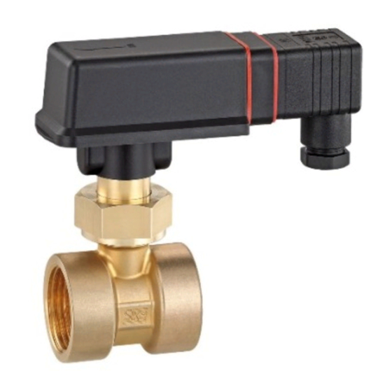
Description de l'appareil VH... / VK... Description de l'appareil Les commutateurs de débit SIKA sont destinés au contrôle des minima et maxima du débit de liquides. Composants Commutateur de débit : Principe de fonctionnement : Le commutateur de débit est constitué d’un système de palette (1) au bout duquel se trouve un aimant permanent (2). -
Page 45: Commutateur De Débit De Type Vh
VH... / VK... Description de l'appareil 1.1.1 Commutateur de débit de type VH...X Le dernier caractère de la référence des commutateurs de débit conçus pour le domaine Ex est un « X » ( plaque signalétique). Les commutateurs ont été soumis à une évaluation du risque d’allumage selon DIN EN 13463-1 : 2002 et amendement 1 : 2003. -
Page 46: Consignes De Sécurité
SIKA offre une assistance personnelle ou de la littérature adéquate pour l’utilisation des pro- duits tandis que le client, lui, détermine si les produits sont adaptés à l’application. -
Page 47: Conditions Supplémentaires Pour Le Commutateur De Débit De Type Vh
VH... / VK... Spécifications des matériaux des pièces mouillés Si le milieu à contrôler présente une température très élevée, les commutateurs de débit et leurs raccords deviennent aussi très chauds. Evitez tout contact et éloignez les objets sensibles aux températures élevées. Protégez le commutateur de débit des champs magnétiques externes de l’environnement proche car ils peuvent altérer le fonctionnement de l'appareil. -
Page 48: Installation Du Commutateur De Débit
Conditions supplémentaires pour le commutateur de débit de type VH...X Pour le choix du lieu de montage, tenez compte des valeurs limites indiquées ( § 9 « Données techniques »). - 48 - © SIKA • Ea3000_FlowSwitch • 02/2014... -
Page 49: Commutateur De Débit À Pièce Tubulaire
VH... / VK... Installation du commutateur de débit Au montage et avant la mise en service, assurez-vous que les raccords mécaniques sont techniquement étanches. Il faut tenir compte de l’étanchéité des éléments de vissage lors de la détermination des zones. -
Page 50: Installation Du Commutateur De Débit
Montage dans manchons à filetage intérieur G½: V- -06M... ab DN 50 - conduites horizontales (commutateur debout) V- -07M... ab DN 50 - conduites verticales. Attention : Il faut absolument observer la hauteur de monta- - 50 - © SIKA • Ea3000_FlowSwitch • 02/2014... -
Page 51: Branchement Électrique
VH... / VK... Branchement électrique Branchement électrique 5.1 Généralités sur le branchement électrique DANGER ! Danger de mort par électrocution ! Seul un électricien est autorisé à effectuer le branchement électrique. Effectuer le branchement électrique de l’installation sans tension puis raccorder les fils sur le circuit. -
Page 52: Connecteurs De Capteur M12X1 (4 Pôles)
5.3 Connecteurs de capteur M12x1 (4 pôles) Utilisez uniquement des prises femelles appropriées M12x1 pour la connexion. Ces ac- cessoires sont livrables avec fil de raccordement ou à assembler. Brochage du connecteur : Fig. 14 - 52 - © SIKA • Ea3000_FlowSwitch • 02/2014... -
Page 53: Câble De Connexion Fixe
VH... / VK... Régler l’unité de commutation 5.4 Câble de connexion fixe Connectez le fil de connexion comme illustré ( Fig.15, Fig. 16) : Contact standard : Contact inverseur : Commutateur de débit de type Commutateur de débit de type seulement commutateur de dé- VH3.../VK3... -
Page 54: Commutateur De Débit De Type Vhs
IMPORTANT ! Soyez attentif lors du réglage fin ! Aucun réglage fin n'est possible avec les versions VHS06..., VHS07..., VKS06..., VKS07..., VK306... et VK307..Vous pouvez changer de type de contact en réglant le dispositif de commutation. - 54 - © SIKA • Ea3000_FlowSwitch • 02/2014... -
Page 55: Commutateur De Débit De Type Vh3
VH... / VK... Entretien et nettoyage 6.4 Commutateur de débit de type VH3... Pour régler l’unité de commutation, desserrez la Contact de traivail (fléche rouge) vis d’arrêt (à six pans creux SW 1,5). haut débit Déplacer l’unité de commutation jusqu’à ce que la faible débit flèche rouge soit visible à... -
Page 56: Démontage Et Élimination
La/le VH... / VK... se compose de différents matériaux ( § 3). Il ne peut pas être jetée ensemble avec les déchets ménagers. Emportez la/le VH... / VK... à votre centre local de recyclage renvoyez la/le VH... / VK... à votre fournisseur ou à SIKA. - 56 - © SIKA • Ea3000_FlowSwitch • 02/2014... -
Page 57: Données Techniques
VH... / VK... Données techniques Données techniques Les données techniques de type personnalisé peuvent être différentes de celles de la pré- sente notice. Veuillez tenir compte des indications sur la plaque signalétique. Commutateur de débit de type VH... et VK... Série VHS... -
Page 58: Débit Maximal Des Commutateurs De Débit
24 mm) 10 Homologations Les commutateurs de débit SIKA sont homologués par le contrôle technique TÜV de Rhéna- nie, estampille de contrôle R 60019031 du 29.08.2007 (ne s'applique pas au modèle avec connecteur de capteur M12x1 ni au modèle VH...X). -
Page 59: Déclaration De Conformité Ue
VH... / VK... Déclaration de conformité UE 11 Déclaration de conformité UE Sous réserve de modification techniques - 59 -... - Page 60 Instruments de mesure de débit Elektronische Mess- & Kalibriertechnik Electronic measuring- & calibration instruments Appareillages électroniques de mesure et matériels de calibration SIKA Dr.Siebert & Kühn GmbH & Co. KG Struthweg 7–9 D-34260 Kaufungen Germany +49 (0)5605 803-0 +49 (0)5605 803-54 ...