Table des Matières
Publicité
Les langues disponibles
Les langues disponibles
Liens rapides
® ® ® ®
KARA
KARA
KARA
KARA
modular wst
modular wst
modular wst
modular wst
® ® ® ®
KARA
KARA
KARA
KARA
ligne source wst
ligne source wst
ligne source wst
ligne source wst
VERSION 1.3
VERSION 1.3
VERSION 1.3
VERSION 1.3
® ® ® ®
line source
line source
line source
line source
® ® ® ®
modulaire
modulaire
modulaire
modulaire
w w w . l - a c o u s t i c s . c o m
USER MANUAL
MANUEL D'UTILISATION
EN
FR
Publicité
Chapitres
Table des Matières

Manuels Connexes pour L-Acoustics KARA


Sommaire des Matières pour L-Acoustics KARA
- Page 1 ® ® ® ® KARA KARA KARA KARA ® ® ® ® modular wst modular wst modular wst modular wst line source line source line source line source ® ® ® ® KARA KARA KARA KARA ® ® ® ®...
- Page 2 w w w . l - a c o u s t i c s . c o m...
-
Page 3: Safety Warnings
Heed all safety warnings Follow all instructions ® The user should never incorporate equipment or accessories not approved by L-ACOUSTICS Sound Levels Sound systems are capable of producing high Sound Pressure Levels which can be dangerous and potentially cause hearing damage especially when exposed to them over a long period of time. -
Page 4: Ec Declaration Of Conformity
Head of Research & Development dept. Maximum flown vertical array configurations: - General standard: 24 KARA. - BGV standard: 18 KARA. w w w . l - a c o u s t i c s . c o m... -
Page 5: Table Des Matières
INSTALLATION Flying or stacking KARA.............................9 Connecting KARA..............................9 OPERATION System configuration............................11 FULL RANGE mode............................11 7.2.1 Description............................11 7.2.2 Connecting KARA to LA8 .........................12 7.2.3 [KARA] preset ..........................12 HIGH-PASS mode ............................13 7.3.1 Description............................13 7.3.2 Connecting KARA to LA8 .........................13 7.3.3 [KARA_FI] preset ..........................13 LOW EXTENSION mode ..........................14... -
Page 6: Introduction
Cross-references section. Unpacking ® Carefully open the shipping carton and check the product for any noticeable damage. Each L-ACOUSTICS product is tested and inspected before leaving the factory and should arrive in perfect condition. If found to be damaged, notify the shipping company or the distributor immediately. Only the consignee may initiate a claim with the carrier for damage incurred during shipping. - Page 7 The L-ACOUSTICS SP.7, SP10, and SP25 Loudspeaker cables with respective lengths of 0.7 m/2.3 ft, 10 m/32.8 ft, and 25 m/82 ft will allow connecting KARA to KARA and can also be used to connect KARA to LA8. Each ®...
- Page 8 KARA-PULLBACK KARA-MINIBU Six KARA enclosures KARA-MINIBUEX KARA-ANGARMEX M-JACK Figure 1: KARA system components (part 1) w w w . l - a c o u s t i c s . c o m KARA_UM_ML_1-3 6 6 6 6 en...
- Page 9 LA NETWORK MANAGER SP.7 SP25 SP10 DOFILL-LA8 DO10 DO25 Figure 2: KARA system components (part 2) w w w . l - a c o u s t i c s . c o m KARA_UM_ML_1-3 7 7 7 7 en...
-
Page 10: Kara ® Enclosure
® enclosure and one 3” HF diaphragm compression driver coupled to DOSC waveguide. Based on a bi-amplified active 2-way design, the nominal impedance of the KARA enclosure is 8 ohms for each of the HF and LF sections. ® ®... -
Page 11: Installation
The KARA enclosure is driven and powered by the dedicated L-ACOUSTICS LA8 amplified controller. Each of the LA8 amp channel pairs 1/2 and 3/4 can drive up to three KARA enclosures in parallel. For more details please refer to the LA8 User manual [3.4]. - Page 12 (2.7 load) According to the calculation in Table 2, one DO25 cable (4 mm², 25 m) can be used to power two KARA in parallel load) with a damping factor still greater than 20. w w w . l - a c o u s t i c s . c o m...
-
Page 13: Operation
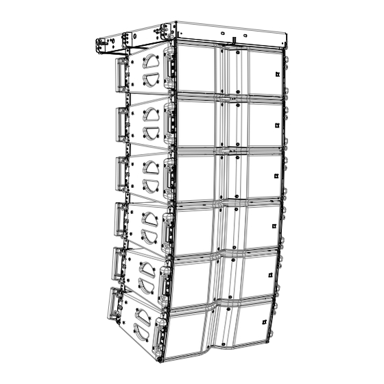
[3.4]. FULL RANGE mode 7.2.1 Description In FULL RANGE mode KARA operates within its nominal bandwidth (55 Hz – 20 kHz) for standalone applications not requiring low frequency extension. [KARA] Figure 5: Standalone KARA line source system example w w w . -
Page 14: Connecting Kara To La8
Connecting KARA to LA8 The first two KARA enclosures are connected to the output channel pairs 1/2 and 3/4 of the LA8 controller. Two additional KARA enclosures can be connected in parallel with each first one. Therefore a single LA8 amplified controller can drive up to six KARA enclosures (see Figure 6). -
Page 15: High-Pass Mode
HIGH-PASS mode 7.3.1 Description In HIGH-PASS mode, the KARA is 100 Hz high-pass filtered and is intended to be used as a fill distributed system to reinforce a main system. Figure 7: KARA distributed reinforcement system example 7.3.2 Connecting KARA to LA8 The first two KARA enclosures are connected to the output channel pairs 1/2 and 3/4 of the LA8 controller. -
Page 16: Low Extension Mode
7.4.1 Description In LOW EXTENSION mode KARA operates within its nominal bandwidth (55 Hz – 20 kHz) to allow combinations with the dedicated complementary SB18 subwoofer and/or the high-power SB28 subwoofer. The bandwidth of the system is extended down to 32 Hz with the SB18 and 25 Hz with the SB28. - Page 17 Note2: A small KARA array (typically composed of 6 enclosures as shown in Figure 10) of standard curvature provides a flat contour. If needed, the KARA contour can be reinforced in the low frequency domain using the LF CONTOUR tool of LA NETWORK MANAGER Software [3.4] with frequency set at 180 Hz and gain set between 0 and 4 dB.
- Page 18 Note1: A small KARA array (typically composed of 6 enclosures as shown in Figure 12) of standard curvature provides a flat contour. If needed, the KARA contour can be reinforced in the low frequency domain using the LF CONTOUR tool of LA NETWORK MANAGER Software [3.4] with frequency set at 180 Hz and gain set between 0 and 4 dB.
- Page 19 SB28 User manual [3.4]). Note2: A small KARA array (typically composed of 6 enclosures as shown on the left side of Figure 13) of standard curvature provides a flat contour. If needed, the KARA contour can be reinforced in the low frequency domain using the LF CONTOUR tool of LA NETWORK MANAGER Software [3.4] with frequency set at 180 Hz and gain set...
-
Page 20: Connecting Kara To La8
Connecting KARA to LA8 The first two KARA enclosures are connected to the output channel pairs 1/2 and 3/4 of the LA8 controller. Two additional KARA enclosures can be connected in parallel with each first one. Therefore a single LA8 amplified controller can drive up to six KARA enclosures (see Figure 14). -
Page 21: Care And Maintenance
Oxidation-resistant screws and rigging points. However, in order to ensure product performance and safety, it is essential to frequently inspect the KARA cabinet. These checks need to be done on a regular basis depending on the conditions of use. The testing procedure consists of three steps as described in [8.2]. -
Page 22: Authorized Service Procedures
The replacement kits (KR) available for the customer are shown in Figure 15 and listed in Table 6 with reference to the corresponding service procedures. Table 7 is a list of all tools and material needed for KARA service (not included). -
Page 23: Front Face (Including Hf Protection Fabric)
8.3.2 Front face (including HF protection fabric) Replacement kit and tools ® KR KARAGR or KR TISSU, electric screwdriver with torque selector (N.m or in.lb ), 5 mm hex bit, T30 Torx bit, KR LOCKBLUE. Front face removal procedure Put the enclosure with rear side on the workbench and logo on the right. Remove a fin on one side by removing both hex screws (5 mm hex bit). -
Page 24: Lf Transducers
® ® ® ® KARA KARA KARA KARA ® ® ® ® M M M M O O O O DULAR DULAR DULAR DULAR WST LINE SOURCE LINE SOURCE LINE SOURCE LINE SOURCE user manual user manual user manual user manual VERSION 1.3... -
Page 25: Hf Diaphragm
8.3.6 HF diaphragm Replacement kit and tools ® KR HSBC34, sine wave generator, electric screwdriver with torque selector (N.m or in.lb ), 3 mm hex bit, T30 Torx bit, KR LOCKBLUE, 2-sided tape. HF diaphragm removal procedure ® Remove the connector plate by removing the 6 Torx screws (T30 bit). -
Page 26: Specifications
26 kg / 57 lb Vertical array rigging M-BUMP rigging frame. Certified for flying up to 24 KARA or 4 SB18/12 KARA and stacking up to 9 KARA (on ground or SB18) or 2 SB18/6 KARA. Inter-enclosure angles: 0, 1, 2, 3, 4, 5, 7.5, 10°. -
Page 27: Déclarations De Sécurité
2. Suivre les consignes de sécurité 3. Suivre les instructions ® 4. N’utiliser en aucun cas des équipements ou accessoires non approuvés par L-ACOUSTICS 5. Niveaux sonores Les systèmes de sonorisation sont capables de délivrer un niveau sonore SPL nuisible à la santé humaine. -
Page 28: Déclaration De Conformité Ce
Responsable Recherche & Développement Configurations maximales en levage vertical : - Standard général : 24 KARA. - Standard BGV : 18 KARA. w w w . l - a c o u s t i c s . c o m... - Page 29 Déballage du produit ................................4 Liens internet ..................................4 ® SYSTÈME KARA ® ENCEINTE KARA INSTALLATION Levage et posage du KARA ..............................9 Connexion du KARA................................9 EXPLOITATION Configuration d’un système............................... 11 Le mode LARGE BANDE..............................11 7.2.1 Description ..............................11 7.2.2...
-
Page 30: Introduction
Si le produit nécessite une réparation ou pour tout renseignement sur la garantie, contacter un distributeur agréé. Les ® coordonnées du distributeur le plus proche sont disponibles sur le site internet L-ACOUSTICS Références croisées Dans l’ensemble du manuel, un nombre entre crochets fait référence à une section. Par exemple, [Erreur ! Source du renvoi introuvable.] fait référence à... -
Page 31: Système Kara
Les câbles haut-parleurs L-ACOUSTICS SP.7, SP10, et SP25 de longueurs respectives 0.7 m/2.3 ft, 10 m/32.8 ft, et 25 m/82 ft permettent de connecter deux KARA entre eux et également le KARA au LA8. Chaque câble comporte 4 ® conducteurs de section 4 mm (13 SWG, 11 AWG) et sont munis de connecteurs SpeakON 4 points. - Page 32 Six enceintes KARA KARA-MINIBUEX KARA-ANGARMEX M-JACK Figure 1 : Éléments du système KARA (partie 1) w w w . l - a c o u s t i c s . c o m KARA_UM_ML_1-3 6 6 6 6 fr...
- Page 33 SP25 SP.7 SP10 DOFILL-LA8 DO10 DO25 Figure 2 : Éléments du système KARA (partie 2) w w w . l - a c o u s t i c s . c o m KARA_UM_ML_1-3 7 7 7 7 fr...
- Page 34 HF 3” à chambre de compression et diaphragme couplé à un guide d’onde DOSC Sur la base d’un design 2 voies actives bi-amplifiées, l’impédance nominale de l’enceinte KARA est de 8 ohms pour chaque section LF et HF.
-
Page 35: Installation
• Posage d’au plus 9 KARA ou 2 SB18/6 KARA sur la plateforme M-BUMP/M-BAR/M-JACK. • Posage d’au plus 4 SB18/9 KARA en plaçant la ligne SB18 directement sur le sol (pour des surfaces parfaitement horizontales et régulières UNIQUEMENT) et la ligne KARA sur la structure M-BUMP. - Page 36 (8 ) (4 ) (2,7 ) Selon le Tableau 2, un câble DO25 (4 mm², 25 m) peut alimenter deux enceintes KARA (impédance de 4 ) avec un facteur d’amortissement supérieur à 20. w w w . l - a c o u s t i c s . c o m...
-
Page 37: Exploitation
Le mode LARGE BANDE 7.2.1 Description En mode LARGE BANDE, le KARA fonctionne dans sa bande passante nominale (55 Hz – 20 kHz) pour des applications en système principal sans renfort sub-grave. [KARA] Figure 5 : Exemple de ligne source KARA en système principal w w w . -
Page 38: Preset [Kara]
7.2.3 Preset [KARA] Le preset [KARA] établit un contour dédié aux applications de moyenne et longue portée dans la bande passante 55 Hz- 20 kHz. Dans le menu de l’interface utilisateur du contrôleur amplifié LA8, sélectionner LOAD PRESET puis le preset [KARA]. -
Page 39: Raccordement Du Kara Au La8
Le mode PASSE-HAUT 7.3.1 Description En mode PASSE-HAUT, les enceintes KARA sont filtrées en passe-haut à 100 Hz et s’utilisent en système distribué en renfort d’un système principal. Figure 7 : Exemple de système de renfort distribué KARA 7.3.2 Raccordement du KARA au LA8 Les deux premières enceintes KARA sont raccordées aux paires de canaux d’amplification 1/2 et 3/4 du contrôleur LA8. -
Page 40: Le Mode Extension Grave
Figure 9). IMPORTANT Si la ligne SB18 est levée à proximité et à côté de la ligne KARA, cette limitation n’est plus nécessaire (voir la partie droite de la Figure 9). Note : Deux arrangements des lignes SB18 sont possibles selon la directivité désirée : omnidirectionnelle ou cardioïde. - Page 41 L’association du KARA et du LF CONTOUR permet d’atteindre des résultats sans précédents lorsque les KARA sont levés et les SB18 posés au sol. Ceci est dû à la bande passante étendue du KARA ainsi qu’à ses performances dans le domaine grave.
- Page 42 L’association du KARA et du LF CONTOUR permet d’atteindre des résultats sans précédents lorsque les KARA sont levés et les SB28 posés au sol. Ceci est dû à la bande passante étendue du KARA ainsi qu’à ses performances dans le domaine grave.
- Page 43 L’association du KARA et du LF CONTOUR permet d’atteindre des résultats sans précédents lorsque les ensembles KARA/SB18 sont levés et les SB28 posés au sol. Ceci est dû à la bande passante étendue du KARA ainsi qu’à ses performances dans le domaine grave.
-
Page 44: 7.4.2 Connexion Du Kara Au La8
VERSION 1.3 7.4.2 Connexion du KARA au LA8 Les deux premières enceintes KARA se raccordent aux paires de canaux 1/2 et 3/4 du contrôleur amplifié LA8. Deux enceintes KARA supplémentaires peuvent être connectées en parallèle avec chaque première. Un seul contrôleur amplifié... -
Page 45: Entretien Et Maintenance
Toutefois, pour assurer les performances et la sécurité du produit, il est indispensable d’inspecter fréquemment l’enceinte KARA. La fréquence de ces vérifications dépend des conditions d’utilisation du système. La procédure de vérification comprend essentiellement trois étapes décrites en section [8.2]. -
Page 46: Procédures De Maintenance Autorisées
KARA (non inclus). ® L’entretien ou la réparation de toute autre partie doit être confié à un représentant L-ACOUSTICS agréé. Dans le cas contraire, l’utilisateur peut être exposé à des situations dangereuses et la garantie ne sera plus applicable. -
Page 47: Face Avant (Tissu De Protection Hf Inclus)
8.3.2 Face avant (tissu de protection HF inclus) Kit de remplacement et outils KR KARAGR ou KR TISSU, visseuse électrique avec sélecteur de couple (N.m or in.lb ), embout BTR 5 mm, embout ® Torx T30, KR LOCKBLUE. Démontage de la face avant Placer l’enceinte face arrière sur le plan de travail et logo à... -
Page 48: Transducteurs Lf
® ® ® ® KARA KARA KARA KARA ® ® ® ® LIGNE SOURCE LIGNE SOURCE LIGNE SOURCE LIGNE SOURCE WST MODULAIRE MODULAIRE MODULAIRE MODULAIRE MANUEL D’UTILISATION NUEL D’UTILISATION NUEL D’UTILISATION NUEL D’UTILISATION VERSION 1.3 8.3.4 Transducteurs LF Kit de remplacement et outils KR HPPH85, visseuse électrique avec sélecteur de couple (N.m or in.lb... -
Page 49: Diaphragme Hf
8.3.6 Diaphragme HF Kit de remplacement et outils KR HSBC34, générateur de signaux sinusoïdaux, visseuse électrique avec sélecteur de couple (N.m or in.lb ), embout ® BTR 3 mm, embout Torx T30, KR LOCKBLUE, ruban adhésif double-face. Démontage d’un diaphragme HF ®... -
Page 50: Spécifications Techniques
M-BUMP structure d’accrochage. Certifiée pour lever jusqu’à 24 KARA ou en ligne verticale 4 SB18/12 KARA ou poser jusqu’à 9 KARA (au sol ou sur SB18) ou 2 SB18/6 KARA. Angles inter-éléments : 0, 1, 2, 3, 4, 5, 7.5, 10°. - Page 51 w w w . l - a c o u s t i c s . c o m...
- Page 52 Tout ou partie de cette publication ne peut être reproduit ou transmis ® sous aucune forme ni aucun moyen sans l’accord écrit de L-ACOUSTICS w w w . l - a c o u s t i c s . c o m...