
Manuels Connexes pour Vega VIB S 61


Sommaire des Matières pour Vega VIB S 61
-
Page 1: Betriebsanleitung
Betriebsanleitung Operating instructions manual Manuel de mise en service Instrucción de servicio VEGAVIB S 61... -
Page 2: Table Des Matières
Betriebsanleitung Betriebsanleitung Operating instructions manual Manuel de mise en service Instrucción de servicio Inhaltsverzeichnis Inhaltsverzeichnis Ausbauschritte Entsorgen Zu Ihrer Sicherheit Anhang Autorisiertes Personal Technische Daten Bestimmungsgemäße Verwendung Maße Warnung vor Fehlgebrauch Gewerbliche Schutzrechte Allgemeine Sicherheitshinweise Warenzeichen CE-Konformität Sicherheitshinweise für Ex- Bereiche Produktbeschreibung Aufbau... -
Page 3: Zu Ihrer Sicherheit
Zu Ihrer Sicherheit Betriebsanleitung 1 Zu Ihrer Sicherheit spezifischen Installationsstandards sowie die geltenden Sicherheitsbestimmungen und Unfall- verhütungsvorschriften zu beachten. 1.1 Autorisiertes Personal Das Gerät darf nur in technisch einwandfreiem und Sämtliche in dieser Betriebsanleitung beschriebe- betriebssicheren Zustand betrieben werden. Der nen Handhabungen dürfen nur durch ausgebilde- Betreiber ist für den störungsfreien Betrieb des tes und vom Anlagenbetreiber autorisiertes Fach-... -
Page 4: Arbeitsweise
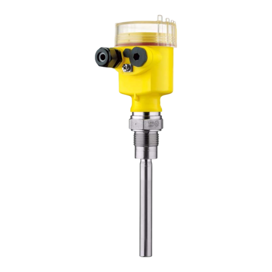
Montieren 2.2 Arbeitsweise Einsatzbereich 3 Montieren Der VEGAVIB S 61 ist ein Grenzstandsensor mit Schwingstab zur Grenzstanderfassung. 3.1 Allgemeine Hinweise Er ist konzipiert für industrielle Einsätze in allen Bereichen der Verfahrenstechnik und wird in Schaltpunkt Schüttgütern eingesetzt. Grundsätzlich kann der VEGAVIB S 61 in jeder beliebigen Lage eingebaut werden. -
Page 5: An Die Spannungsversorgung
An die Spannungsversorgung anschließen 3.2 Montagehinweise nen Installationsvorschriften. Verbinden Sie den VEGAVIB S 61 grundsätzlich mit der Behältererde Stutzen (PA) bzw. bei Kunststoffbehältern mit dem Das Schwingelement sollte möglichst frei in den nächstgelegenen Erdpotenzial. Seitlich am Ge- Behälter ragen. rätegehäuse befindet sich dazu eine Erdungs- klemme zwischen den Kabelverschraubungen. -
Page 6: Anschlussplan
An die Spannungsversorgung anschließen 1 2 3 4 1 2 3 4 Abb. 5: Ausführung: Elektronik „T“ - Transistor (NPN/PNP) Spannungsversorgung Kontrollleuchte Dichteanpassung (DIL-Schalter) Abb. 3: Anschlussschritte 5 und 6 Betriebsartenumschaltung min/max (DIL-Schalter) 4.3 Anschlussplan 4 5 6 7 8 3 4 5 6 7 8 Abb. -
Page 7: In Betrieb Nehmen
In Betrieb nehmen 5 In Betrieb nehmen Füllstand Schaltzu- Kontroll- stand leuchte 5.1 Allgemein Betriebsart Relais strom- max. führend Überlauf- oder Funktion/Aufbau schutz Transistor lei- Auf dem Elektronikeinsatz finden Sie folgende Grün Anzeige- und Bedienelemente: Betriebsart Relais strom- DIL-Schalter zur Dichteanpassung max. -
Page 8: Instandhalten
Das vorliegende Gerät unterliegt nicht der WEEE- Im Internet können Sie auf unserer Homepage Richtlinie 2002/96/EG und den entsprechenden www.vega.com unter: "Downloads - Formulare und nationalen Gesetzen. Führen Sie das Gerät direkt Zertifikate - Reparaturformular" ein Rücksendefor- einem spezialisierten Recyclingbetrieb zu und mular (23 KB) herunterladen. -
Page 9: Anhang
Anhang 8 Anhang 8.1 Technische Daten Allgemeine Daten Werkstoff 316L entspricht 1.4404 oder 1.4435 Werkstoffe, medienberührt Prozessanschluss 316L Schwingstab 316L, 318 S13 (1.4462) Verlängerungsrohr 316L Prozessdichtung Klingersil C-4400 Werkstoffe, nicht medienberührt Gehäuse Kunststoff PBT (Polyester) Gehäusedeckel Kunststoff PA 12 (Polyamid, klar) Dichtung zwischen Ge- Silikon häuse und Gehäuse-... - Page 10 Anhang Prozessbedingungen Prozessdruck -1 … 16 bar/-100 … 1600 kPa Prozesstemperatur -50 … +150 °C Dichte > 0,1 g/cm³ Korngröße max. ca. 20 mm Elektromechanische Daten Kabeleinführung/Stecker 1 x Kabelverschraubung M20 x 1,5 (Kabel: ø 5 … 9 mm), 1 x Blindstopfen M20 x 1,5;...
-
Page 11: Maße
Anhang 8.3 Gewerbliche Schutzrechte 8.2 Maße VEGA product lines are global protected by industrial property rights. Further information see http://www.vega. com. ~ 69 mm Only in U.S.A.: Further information see patent label at the ø 81 mm sensor housing. VEGA Produktfamilien sind weltweit geschützt durch gewerbliche Schutzrechte. -
Page 12: Operating Instructions Manual
Operating instructions manual Betriebsanleitung Operating instructions manual Manuel de mise en service Instrucción de servicio Content Content Supplement Technical data For your safety Dimensions Industrial property rights Authorised personnel Trademark Appropriate use Warning about misuse General safety instructions CE conformity Safety instructions for Ex areas Product description Configuration... -
Page 13: For Your Safety
For your safety Operating instructions manual 1 For your safety The instrument must only be operated in a technically flawless and reliable condition. The operator is responsible for trouble-free operation of 1.1 Authorised personnel the instrument. All operations described in this operating instruc- During the entire duration of use, the user is tions manual must be carried out only by trained obliged to determine the compliance of the... -
Page 14: Principle Of Operation
Mounting 2.2 Principle of operation 3 Mounting Area of application 3.1 General instructions VEGAVIB S 61 is a level sensor with vibrating rod for level detection. Switching point It is designed for industrial use in all areas of In general, VEGAVIB S 61 can be installed in any process technology and is used in bulk solids. -
Page 15: Connecting To Power Supply
Connecting to power supply Filling opening The data for voltage supply are specified in chapter "Technical data" in the "Supplement". Mount the instrument in such a way that the vibrating rod does not protrude directly into the Selecting connection cable filling stream. -
Page 16: Wiring Plan
Connecting to power supply 1 2 3 4 1 2 3 4 Fig. 13: Version: Electronics „T“ - transistor (NPN/PNP) Voltage supply Control lamp Density adaptation (DIL switch) Fig. 11: Connection steps 5 and 6 Mode adjustment min./max. (DIL switch) 4.3 Wiring plan 4 5 6 7 8 3 4 5 6 7 8... -
Page 17: General Information
Set up 5 Set up Level Switching Control status lamp 5.1 General information Mode max. Relay ener- Overflow pro- gized tection Function/Configuration transistor con- On the electronics module you will find the ducts Green following indicating and adjustment elements: Mode max. Relay deener- DIL switch for density adaptation Overflow pro-... -
Page 18: Instrument Repair
Pass the instrument directly on to a speci- However, if these measures are not successful, alised recycling company and do not use the call the VEGA service hotline in urgent cases under municipal collecting points. These may be used the phone no. +49 1805 858550. -
Page 19: Technical Data
Supplement 8 Supplement 8.1 Technical data General data Material 316L corresponds to 1.4404 or 1.4435 Materials, wetted parts Process fitting 316L Vibrating rod 316L, 318 S13 (1.4462) Extension tube 316L Process seal Klingersil C-4400 Materials, non-wetted parts Housing plastic PBT (Polyester) Housing cover Plastic PA 12 (polyamide, clear) Seal between housing and... -
Page 20: Process Conditions
Supplement Process conditions Process pressure -1 … 16 bar/-100 … 1600 kPa Process temperature -50 … +150 °C Density > 0.1 g/cm³ Granular size max. approx. 20 mm Electromechanical data Cable entry/plug 1 x cable entry M20 x 1.5 (cable: ø 5 … 9 mm), 1 x blind stopper M20 x 1.5;... -
Page 21: Dimensions
Supplement 8.3 Industrial property rights 8.2 Dimensions VEGA product lines are global protected by industrial property rights. Further information see http://www.vega. com. ~ 69 mm Only in U.S.A.: Further information see patent label at the ø 81 mm sensor housing. -
Page 22: Manuel De Mise En Service
Manuel de mise en service Betriebsanleitung Operating instructions manual Manuel de mise en service Instrucción de servicio Sommaire Sommaire Etapes de démontage Recyclage Pour votre sécurité Annexe Personnel autorisé Caractéristiques techniques Définition de l'application Encombrement Avertissement en cas de fausse Droits de propriété... -
Page 23: Personnel Autorisé
Pour votre sécurité Manuel de mise en service 1 Pour votre sécurité 1.4 Consignes de sécurité générales L'appareil correspond au standard technologique 1.1 Personnel autorisé actuel et respecte les règlements et directives usuels. L'utilisateur doit suivre scrupuleusement Toutes les manipulations sur l'appareil indiquées les consignes de sécurité... -
Page 24: Description Du Produit
Description du produit de l'amplitude de vibration. Celle-ci est détectée 2 Description du produit par l'étage électronique intégré puis convertie en un ordre de commutation. 2.1 Présentation Compris à la livraison 2.3 Stockage et transport La livraison comprend : Emballage Capteur de niveau VEGAVIB S 61 Durant le transport jusqu'à... -
Page 25: Consignes De Montage
Raccordement à la tension d'alimentation Manipulation 4 Raccordement à la tension Le détecteur vibrant est un appareil de mesure et d'alimentation doit donc être manipulé en conséquence. Une flexion de l'élément vibrant entraîne la destruction de l'appareil. 4.1 Préparation du raccordement Respecter les consignes de sécurité... -
Page 26: Schéma De Raccordement
Raccordement à la tension d'alimentation 4.3 Schéma de raccordement Introduisez le câble dans le capteur en le passant par le presse-étoupe. Soulevez les leviers d'ouverture des bornes avec un tournevis (voir figure suivante). 4 5 6 7 8 Insérez les fins de conducteurs dans les bornes ouvertes selon le schéma de raccor- dement Rabaissez les leviers des bornes, le ressort... -
Page 27: Mettre En Service
Mettre en service 5 Mettre en service 5.1 Généralité Fonctionnement/présentation Vous trouverez sur le préamplificateur les éléments de réglage et d'affichage suivants : Commutateur DIL pour l'adaptation de la densité Commutateur DIL pour inversion du mode de Fig. 22: Occupation : NPN et PNP fonctionnement - mini./maxi. -
Page 28: Tableau De Fonctionnement
Rouge che à vide Sur internet, vous avez la possibilité de télécharger Panne de ten- Relais désex- sur notre page d'accueil www.vega.com sous : Quelconque sion d'alimen- cité "Téléchargements - Formulaires et certificats - tation Formulaire de réparation" un formulaire de renvoi (mode mini.-... -
Page 29: Démontage
Démontage 7 Démontage 7.1 Etapes de démontage Attention ! Avant de démonter l'appareil, prenez garde aux conditions de process dangereuses comme p. ex. pression dans la cuve, hautes températures, produits agressifs ou toxi- ques etc. Suivez les indications des chapitres "Montage" et "Raccordement à... -
Page 30: Annexe
Annexe 8 Annexe 8.1 Caractéristiques techniques Caractéristiques générales Matériau 316L correspond à 1.4404 ou à 1.4435 Matériaux, en contact avec le produit Raccord process 316L barreau vibrant 316L, 318 S13 (1.4462) Tube prolongateur 316L Joint de process Klingersil C-4400 Matériaux, non en contact avec le produit Boîtier plastique PBT (polyester) Couvercle de boîtier... - Page 31 Annexe Température de stockage et -40 … +80 °C de transport Conditions de process Pression process -1 … 16 bar/-100 … 1600 kPa Température process -50 … +150 °C Densité > 0,1 g/cm³ Granulométrie maxi. env. 20 mm Caractéristiques électromécaniques Entrée de câble/connecteur 1 x presse-étoupe M20 x 1,5 (câble : ø...
-
Page 32: Encombrement
8.2 Encombrement ques techniques" 8.3 Droits de propriété industrielle ~ 69 mm VEGA product lines are global protected by industrial ø 81 mm property rights. Further information see http://www.vega. com. Only in U.S.A.: Further information see patent label at the sensor housing. -
Page 33: Instrucción De Servicio
Instrucción de servicio Betriebsanleitung Operating instructions manual Manuel de mise en service Instrucción de servicio Índice Índice Desmontaje Secuencia de desmontaje Para su seguridad Eliminación Personal autorizado Anexo Empleo acorde con las prescripciones Datos técnicos Advertencia contra uso erróneo Medidas Instrucciones generales de Derechos de protección industrial seguridad... -
Page 34: Instrucción De Servicio
Para su seguridad Instrucción de servicio 1 Para su seguridad 1.4 Instrucciones generales de seguridad 1.1 Personal autorizado El equipo corresponde con el estado tecnológico, Todas las manipulaciones descritas en esta considerando las prescripciones y recomendacio- instrucción de servicio pueden ser realizadas nes normales. -
Page 35: Descripción Del Producto
Descripción del producto 2.3 Almacenaje y transporte 2 Descripción del producto Embalaje 2.1 Construcción Su instrumento se encuentra protegido por un embalaje durante el transporte hasta el lugar de Alcance de suministros empleo. Aquí las solicitaciones normales a causa El alcance de suministros se compone de: del transporte se encuentran aseguradas mediante un control según la norma DIN EN 24180. -
Page 36: Instrucciones De Montaje
Conectar a la alimentación de tensión Manipulación 4 Conectar a la alimentación El interruptor limitador vibratorio es un equipo de de tensión medición y tiene que ser tratado de forma correspondiente. Una deformación del elemento vibratorio conduce a la destrucción del instrumen- 4.1 Preparación de la conexión Prestar atención a las indicaciones de seguri- Advertencia:... -
Page 37: Esquema De Conexión
Conectar a la alimentación de tensión 4.3 Esquema de conexión Destornillar la tapa de la carcasa Zafar la tuerca de unión del racor pasacables Pelar aproximadamente 10 cm (4 in), quitar aproximadamente 1 cm (0.4 in) del aislamiento 4 5 6 7 8 a los extremos de los conductores Empujar el cable en el sensor a través del racor atornillado para cables... -
Page 38: Poner En Funcionamiento
Poner en funcionamiento 5 Poner en funcionamiento 5.1 Generales Funcionamiento/Construcción En la pieza electrónica recambiable se encuentran los elementos de manejo e indicación siguientes: Interruptor DIL para la adaptación de densidad Interruptor DIL para la conmutación de modos de operación - mín/máx. Fig. -
Page 39: Tabla De Funciones
6.2 Línea directa de servicio de 24 horas ración máx. tor de corrien- Protección Si estas medidas no conducen a ningún resultado, contra sobre- llamar la línea directa de servicio VEGA en casos llenado Transistor verde conduce urgentes al Tel. +49 1805 858550. -
Page 40: Desmontaje
Desmontaje 7 Desmontaje 7.1 Secuencia de desmontaje Advertencia: Antes del desmontaje, prestar atención a condiciones de proceso peligrosas tales como p. Ej., presión en el depósito, altas temperaturas, productos agresivos o tóxi- cos, etc. Atender los capítulos "Montaje" y "Conexión a la alimentación de tensión"... -
Page 41: Anexo
Anexo 8 Anexo 8.1 Datos técnicos Datos generales Material 316L equivalente con 1.4404 o 1.4435 Materiales, en contacto con el medio Conexión a proceso 316L Varilla vibratoria 316L, 318 S13 (1.4462) Tubo de extensión 316L Sello del proceso Klingersil C-4400 Materiales, sin contacto con el medio Carcasa Plástico PBT (Poliéster) -
Page 42: Medidas
Anexo Temperatura de almacenaje -40 … +80 °C y transporte Condiciones de proceso Presión de proceso -1 … 16 bar/-100 … 1600 kPa Temperatura de proceso -50 … +150 °C Densidad > 0,1 g/cm³ Granulación máx. ca. 20 mm Datos electromecánicos Entrada de cables/Enchufe 1 x racor atornillado M20 x 1,5 (Cable: ø... -
Page 43: Derechos De Protección Industrial
Anexo 8.3 Derechos de protección industrial 8.2 Medidas VEGA product lines are global protected by industrial property rights. Further information see http://www.vega. com. ~ 69 mm Only in U.S.A.: Further information see patent label at the ø 81 mm sensor housing. - Page 44 Anexo VEGAVIB S 61...
- Page 45 Anexo VEGAVIB S 61...
- Page 46 Anexo VEGAVIB S 61...
- Page 47 Anexo VEGAVIB S 61...
- Page 48 Las informaciones acera del alcance de suministros, aplicación, uso y condiciones de funcionamiento de los sensores y los sistemas de análisis corresponden con los conocimientos existentes al momento de la impresión. © VEGA Grieshaber KG, Schiltach/Germany 2008 32796-01-080108 Änderungen vorbehalten / Subject to change without prior notice /...