Publicité
Les langues disponibles
Les langues disponibles
Liens rapides
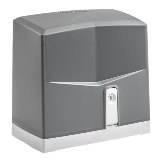
MOVEO
IT OPERATORE IRREVERSIBILE PER
CANCELLI SCORREVOLI
EN IRREVERSIBLE OPERATOR FOR
SLIDING GATES
FR OPERATEUR IRREVERSIBLE
POUR PORTAILS COULISSANTES
ES OPERADOR IRREVERSIBLE PARA
VERJAS CORREDERAS
NL AANDRIJVING VOOR
SCHUIFPOORTEN
DE SELBSTHEMMENDER
TORANTRIEB FÜR SCHIEBETOREN
6-1624870 /R. 5
Operatore - Operateur - Operator -
Operador - Aandrijving - Torantrieb
MOVEO 600
MOVEO 600
MOVEO 700 24V
Alimentazione - Power Supply -
Alimentation - Alimentacion - Voeding
- Stromspannung
230V 50/60Hz
120V 50/60Hz
24Vdc
Centrale di comando - Control unit -
Centrale de commande - Cuadro de mando
- Besturingseenheid - Steuereinheit
BIOS1
BIOS1 120
BIOS1 24
Publicité

Manuels Connexes pour Allmatic MOVEO 700 24V


Sommaire des Matières pour Allmatic MOVEO 700 24V
- Page 1 Alimentation - Alimentacion - Voeding Centrale de commande - Cuadro de mando Operador - Aandrijving - Torantrieb - Stromspannung - Besturingseenheid - Steuereinheit MOVEO 600 230V 50/60Hz BIOS1 MOVEO 600 120V 50/60Hz BIOS1 120 MOVEO 700 24V 24Vdc BIOS1 24...
- Page 2 E: Fotocellule. 2° - Per la sezione ed il tipo dei cavi ALLMATIC consiglia di utilizzare un cavo di tipo H05RN-F con sezione minima di 1,5mm 2 e comunque di attenersi alla norma IEC 364 e alle norme di COLLEGAMENTI ELETTRICI installazione vigenti nel proprio Paese.
- Page 3 LAYOUT IMPIANTO Fig. 1 A - Operatore MOVEO B - Fotocellule esterne C - Cremagliera Modulo 4 D - Selettore a chiave E - Antenna radio F - Lampeggiatore G -Camme finecorsa H - Costa meccanica I - Costa meccanica con sistema wireless. J - Fotocellula per protezione interna K - Colonnina portafotocellula L - Fermi meccanici...
- Page 4 INSTALLAZIONE E POSIZIONAMENTO CONTROPIASTRA 1. Piegare le zanche pre-tagliate fino a 90° come mostrato nell’immagine 2. Inserire le 4 viti (in dotazione) come nell’immagine, dalla parte inferiore alla parte superiore della piastra 3. Avvitare completamente i 4 dadi (in dotazione) come mostrato nell’immagine 4.
- Page 5 FISSAGGIO MOTORE Fig. 5 Per fissare il motore alla contropiastra, inserire ed avvitare i 4 dadi (Fig. 5). Posizionare il motore in parallelo al cancello e con l’ingranaggio sotto alla cremagliera come da Fig. 8. N.B. E’ importante bloccare energicamente i 4 dadi, assicurandosi che durante tutta la corsa del cancello, il motoriduttore sia ben saldo a terra. FISSAGGIO CREMAGLIERA La cremagliera va fissata a una certa altezza rispetto alla piastra di fissaggio del motore (Fig.
- Page 6 POSIZIONAMENTO E REGOLAZIONE FINECORSA MECCANICI Per determinare la corsa della parte mobile si devono posizionare due camme (Fig. 9) alle estremità della cremagliera (Fig. 10). La regolazione della corsa di apertura e chiusura, si ottiene spostando le medesime sui denti della cremagliera. Per bloccare le camme alla cremagliera avvitare a fondo le viti in dotazione.
- Page 7 Fig. 13 Fig. 13 Per installazioni speciali richiedere informazioni ad Allmatic o utilizzare motoriduttori di maggior portata. SBLOCCO In caso di mancanza di corrente, per poter agire manualmente sul cancello è sufficiente inserire l’apposita chiave, ruotarla di 90° ed aprire la leva (Fig.
- Page 8 2° - As far as the cable section and the cable kind are concerned, D: Safety strips and/or other safety devices to keep thrust force within the ALLMATIC suggests to use an H05RN-F cable, with a minimum limits of EN12453 regulation - Appendix A.
- Page 9 SYSTEM LAYOUT Fig. 1 A - MOVEO operator B - Photocells (external) C - Rack M4 D - Key selector E - Tuned antenna F - Flashing lamp G - Limit switch cams H - Safety edge fixed to column I - Safety edge with wireless system J - Photocells (internal) K - Galvanized column for photocells...
- Page 10 BASE PLATE INSTALLATION 1. Push the achors until they are 90° as shown in the picture 2. Insert the 4 screws (supplied) as shown in the image, from the bottom to the top of the backing plate 3. Screw completely the 4 nuts (supplied) as shown in the image 4.
- Page 11 MOTOR FITTING Fig. 5 To fix the motor to the counterplate, insert and screw the 4 nuts (Fig. 5). Position the motor in parallel with the gate and with the gear under the rack as shown in Fig. 8. N.B. It is important to energetically tighten the 4 nuts, making sure that the gearmotor is firmly on the ground during the entire stroke of the gate. RACK FITTING The rack must be fixed at a certain height with respect to the motor fixing plate (Fig.
- Page 12 LIMIT SWITCH FITTING In order to determine the gate travel length, place two cams (Fig. 9) at the ends of the rack (Fig. 10). Move the cams on the rack teeth to adjust their opening and closing travel. To fix the cams to the rack, tighten the screws issued. Note: In addition to the electric stop cams mentioned above, you must also install strong mechanical stops preventing the gate from sliding out from the top guides.
- Page 13 Fig. 13 Fig. 13 For special installations request information from Allmatic or use larger geared motors. RELEASE To move the gate manually it is necessary to release the gearmotor inserting the key, turning it for 90° and open the lever (Fig. 14).
- Page 14 à clé). DESCRIPTION COLOUR 2° - En ce qui concerne la section et le type des câbles, le conseil de ALLMATIC PHASE 1 Noir est celui d’utiliser un câble de type H05RN-F présentant une section minimale de 1,5mm2 et, quoi qu’il en soit, de se conformer à...
- Page 15 LAYOUT DU SYSTÈME Fig. 1 A Operateur MOVEO B Photocellules externes C Crémaillère M4 D Sélecteur E Antenne radio F Clignotant G Limiteurs de course (cames) H Barre palpeuse mécanique fixé sur pilier I Barre palpeuse avec système wireless J Photocellules interne K Poteau zingué...
- Page 16 INSTALLATION E POSITIONNEMENT DE CONTRE PLAQUE 1. Poussez les akors jusqu’à 90 ° comme indiqué sur la photo 2. Insérez les 4 vis (fournies) comme indiqué sur l’image, de bas en haut de la plaque de support. 3. Vissez complètement les 4 écrous (fournis) comme indiqué sur l’image. 4.
- Page 17 FIXATION DU MOTEUR Fig. 5 Pour fixer le moteur sur la contre-plaque, insérer et serrer les 4 écrous à six pans (Fig. 5). Placez le moteur en parallèle avec le portail et avec le pignon sous la crémaillère, comme illustré à la Fig. 8. NOTE Il est important de serrer énergiquement les 4 écrous à...
- Page 18 FIXATION FIN DE COURSE MÉCANIQUE Pour déterminer la course de la partie mobile, il faut positionner deux cames (Fig. 10) sur les extrémités de la crémaillère (Fig. 9). Pour procéder au réglage de la course d’ouverture et de fermeture, il suffit de déplacer les cames sur les crans de la crémaillère. Pour bloquer les cames sur la crémaillère, visser à fond les vis, fournies avec l’équipement.
- Page 19 POSITIONNEMENT DE LA PORTE EN RAPPORT À LE PLAN HORIZONTAL Fig. 13 Fig. 13 Pour les installations spéciales, demandez des informations à Allmatic ou utilisez des motoréducteurs plus grands. DÉBLOCAGE Afin de pouvoir manœuvrer manuellement le vantail, il est important de vérifier que: - Il soit fourni des poignées adaptées sur le vantail.
- Page 20 Seguir las indicaciones del diagrama para el correcto cableado del motor dentro de un panel cerrado a llave). en la central: 2° - Para la sección y el tipo de los cables, ALLMATIC aconseja utilizar cables de tipo H05RN-F con sección mínima de 1,5mm 2 e igualmente atenerse DESCRIPCIÓN COLOR a la norma IEC 364 y a las normas de instalación del propio País.
- Page 21 DISPOSICIÒN DE LA INSTALACIÒN Fig. 1 A - Operador MOVEO B - Fotocélulas externas C - Cremallera Módulo M4 D - Selector de llave E - Antena de radio F - Intermitente G - Limitadores de recorrido (leva) H - Banda de seguridad mecánica I - Banda de seguridad con sistema wireless J - Fotocélulas internas K - Columnas para las fotocélulas...
- Page 22 INSTALACIÓN E POSICIÓN DE LA BASE DE FIJACIÓN 1. Presione los puntos de anclaje precortados en la placa de fijación hasta que estén a 90° como se muestra en la imagen 2. Inserte los 4 tornillos (suministrados) como se muestra en la imagen, desde la parte inferior hasta la parte superior de la placa de soporte 3.
- Page 23 FIJACIÓN MOTOR Fig. 5 Para fijar el motor a la contraplaca, inserte y apriete las 4 tuercas (Fig. 5). Coloque el motor en paralelo con la puerta y con el engranaje debajo del bastidor como se muestra en la Fig. 8. Nótese bien Es importante ajustar firmemente las 4 tuercas, asegurándose de que el motorreductor esté...
- Page 24 FIJACIÓN FINAL DE CARRERA MECÁNICOS Para determinar el recorrido de la parte móvil se tiene que colocar dos limitadores de recorrido (Fig. 9) en los extremos de la cremallera (Fig. 10). La regulación de la abertura y el cierre, se obtiene desplazando la misma sobre los dientes de la cremallera. Para fijar las limitadores de tope de recorrido a la verja, atornillar a fondo los tornillos suministrados.
- Page 25 Fig. 13 Fig. 13 Para instalaciones especiales solicitar información a Allmatic o usar motores de mayor alcance. DESBLOQUE En caso de falta de corriente, para poder accionar manualmente la cancela es suficiente insertar la llave, girarla de 90º y abrir la palanca (Fig. 14).
- Page 26 E: Fotocellen. 2° - Voor de doorsnede en het type kabels raadt ALLMATIC aan om een kabel van het type H05RN-F te gebruiken met een minimale doorsnede van 1,5mm 2 en om in ieder geval te voldoen aan de...
- Page 27 LAY-OUT VAN HET SYSTEEM Afb. 1 A - Aandrijving MOVEO B - Externe fotocellen C - Tandheugel Module 4 D - Sleutelschakelaar E - Antenne F - Knipperlicht G -Nokken eindschakelaars H - Veiligheidscontactlijst I - Veiligheidscontactlijst met draadloos systeem. J - Fotocel voor interne beveiliging K - Fotocel in zuil L - Mechanische aanslagen...
- Page 28 INSTALLATIE EN POSITIONERING VAN DE TEGENPLAAT 1. Buig de voorgesneden klemmen 90 ° zoals weergegeven in de afbeelding 2. Plaats de 4 (meegeleverde) schroeven zoals in de afbeelding, van onder naar boven op de plaat 3. Draai de 4 (meegeleverde) moeren volledig vast zoals weergegeven in de afbeelding 4.
- Page 29 BEVESTIGING MOTOR Afb. 5 Om de motor op de tegenplaat te bevestigen, plaatst u de 4 moeren en draait u deze vast (Afb. 5). Positioneer de motor parallel aan de poort en met het tandwiel onder de tandheugel zoals getoond in Afb. 8. N.B.
- Page 30 POSITIONERING EN AFSTELLING MECHANISCHE EINDSCHAKELAARS Om de slag van het bewegende deel te bepalen, moeten twee nokken worden geplaatst (Afb. 9) aan de uiteinden van de tandheugel (Afb. 10). De afstelling van de openings- en sluitingsslag wordt verkregen door deze op de tanden van de tandheugel te bewegen. Draai de meegeleverde schroeven volledig vast om de nokken aan de tandheugel te bevestigen.
- Page 31 Afb. 13 Afb. 13 Vraag voor speciale installaties informatie aan bij Allmatic of gebruik reductiemotoren met een groter vermogen. ONTGRENDELING Om de poort handmatig te kunnen openen in het geval van een stroomstoring steekt u de speciale sleutel in het slot, draait u deze 90°...
- Page 32 ANMERKUNG: Die Erdung der Anlage ist obligatorisch Die in diesem stones and dirt. Handbuch aufgeführten Daten sind ausschließlich empfohlene Werte. ALLMATIC behält sich das Recht vor, das Produkt zu jedem Zeitpunkt zu modifizieren. Die Anlage muss in Übereinstimmung mit den gültigen Normen und Gesetzen montiert werden.
- Page 33 INSTANDHALTUNG A Torantrieb MOVEO B Lichtschranke Toraußenseitig C Zahnstange M4 D Schlüsselschalter E Antenne F Blinkleuchte G Laufbegrenzer (Nocken) H Sicherheitskontaktleiste auf dem Schiebetor I Sicherheitskontaktleiste mit Wireless System J Lichtschranke Torinnenseitig K Verzinkte Metallsäule als Photozellen träger L Mechanische Anschläge TECHNISCHE EIGENSCHAFTEN IIrreversible Betriebsgeräte für Schiebetoren.
- Page 34 INSTALLATION UNA PLATZIERUNG DER BODENPLATTE 1. Die vorgeschnittenen Klemmen, wie in der Abbildung gezeigt, um 90° falten 2. Setzen Sie die 4 Schrauben (mitgeliefert) wie in der Abbildung gezeigt von unten nach oben auf die Platte ein 3. Ziehen Sie die 4 Muttern (mitgeliefert) wie in der Abbildung gezeigt fest 4.
- Page 35 MOTORBEFESTIGUNG Fig. 5 Um den Antrieb an der Bodenplatte zu befestigen, setzen Sie die 4 Muttern ein und ziehen Sie sie fest (Abb. 5). Positionieren Sie den Antrieb parallel zum Tor und mit dem Zahnrad unter der Zahnstange (Abb. 8). Anmerkung: Es ist wichtig, die 4 Muttern fest zu arretieren und sicherstellen dass der Antrieb während der gesamten Fahrt des Tors fest auf dem Boden steht ZAHNSTANGE...
- Page 36 BEFESTIGUNG DES ENDSCHALTERS Um den Lauf des mobilen Teils zu beenden, müssen zwei Nocken (Abb. 9) an den Enden der Zahnstange positioniert werden (Abb. 10). Die Regulierung des Öffnungs- und Schließlaufes wird erhalten, indem diese entlang der Zahnstangenzähne verschoben werden. Um die Zahnstangennocken festzustellen, müssen die mitgelieferten Schrauben am Boden befestigt werden.
- Page 37 Fig. 13 Fig. 13 Für spezielle Installationen fordern Sie Informationen von Allmatic an oder verwenden Sie größere Getriebemotoren. ENTRIEGELUNG Um das Tor, bei Stromausfall, manuell zu bewegen, den Schlüssel einsetzen, um 90° drehen und den Hebel ziehen (Abb. 14). Um das Tor manuell richtig zu prüfen müssen folgende Punkte beachtet werden:...
- Page 38 Centralina - Control unit - Centrale de commande - Torantrieb - Operater Alimentacion - Stromspannung - Napajanje Cuadro de mando - Steuereinheit - Kontrolna jedinica MOVEO 600 230V 50/60Hz BIOS1 MOVEO 600 120V 50/60Hz BIOS1 120 MOVEO 700 24V 24Vdc BIOS1 24...
- Page 39 NACRT SISTEMA Slika 1 A - MOVEO operater B - Fotoćelije (vanjske) C - Zupčasta šipka M4 D - Birač tipki E - Sinkronizirana antena F - Trepćuća svjetiljka G - Bregice graničnih prekidača Motor opremljen mazivom visokih performansi H - Sigurnosni rub pričvršćen za stub I - Sigurnosni rub sa bežičnim sistemom J - Fotoćelije (interne) K - Pocinčani stubac za fotoćelije...
- Page 40 INSTALACIJA BAZNE PLOČE 1. Umetnite ankere pod uglom od 90° kako je prikazano na slici 2. Umetnite 4 šarafa (uključeni u paket) kako je prikazano na slici, od dna prema vrhu potporne ploče 3. Potpuno zavrnite 4 matice (uključene u paket) kako je prikazano na slici 4.
- Page 41 UKLAPANJE MOTORA Slika 5 Za pričvršćivanje motora na kontraploču, umetnite i zavrnite 4 matice (Slika 5). Postavite motor paralelno sa kapijom tako da prijenosnik bude postavljen ispod zupčaste šipke kako je prikazano na Slici 8. N.B. Važno je čvrsto zategnuti 4 matice, vodeći računa da je motor s prijenosnikom čvrsto na tlu tijekom cijelog hoda vrata. UKLAPANJE ZUPČASTE ŠIPKE Zupčasta šipka mora biti pričvršćena na određenoj visini u odnosu na ploču za pričvršćivanje motora (Slika 3).
- Page 42 UKLAPANJE GRANIČNOG PREKIDAČA Za određivanje dužine kretanja kapije, postavite dvije bregice (Slika 9) na krajevima zupčaste šipke (Slika 10). Pomjerite bregice po zupcima zupčanice kako biste podesili kretanje otvaranja i zatvaranja istih. Za fiksiranje bregica na zupčanici, zategnite priložene šarafe. Napomena: Pored gore navedenih bregica električnih kočnica, također morate ugraditi jake mehaničke kočnice kako kapija ne bi iskliznula iz gornjih vodilica.
- Page 43 POZICIONIRANJE KAPIJE U ODNOSU NA HORIZONTALNU OSNOVU Slika 13 Slika13 Za posebne instalacije zahtijevajte informaciju od Allmatica ili koristite veće motore sa prijenosnikom. OSLOBAĐANJE Za ručno pomicanje kapije potrebno je osloboditi motor s prijenosnikom umetanjem ključa, okretanjem istog za 90° i otvaranjem poluge (Slika 14).
- Page 44 ALLMATIC S.r.l Via dell’Artigiano, n°1 – Z.A. - Loc. Lentiai 32026 Borgo Valbelluna (BL) - ITALY Tel. 0437 751175 – 751163 r.a. 6-1624870 www.allmatic.com - E-mail: info@allmatic.com...