Table des Matières
Publicité
Les langues disponibles
Les langues disponibles
Liens rapides
INSTALLER: LEAVE THIS MANUAL WITH THE APPLIANCE.
CONSUMER: RETAIN THIS MANUAL FOR FUTURE REFERENCE.
NEVER LEAVE CHILDREN OR OTHER AT RISK INDIVIDUALS ALONE WITH THE APPLIANCE.
MODEL TPS35/TPI35 MEET THE 2015 U.S ENVIRONMENTAL PROTECTION AGENCY (E.P.A.) PELLET FUEL EMISSION LIMITS FOR PELLET APPLIANCES SOLD
AFTER MAY 15, 2015, 40 C.F. R. PART 60. THESE STOVES HAVE BEEN TESTED AND LISTED BY INTERTEK TESTING SERVICES TO STANDARDS: ASTM E 1509,
TPS35
PELLET STOVE
TPI35
PELLET INSERT
CERTIFIED FOR CANADA AND UNITED STATES USING ANSI/CSA METHODS.
SAFETY INFORMATION
WARNING
!
PLEASE READ ENTIRE MANUAL
BEFORE YOU INSTALL OR USE THIS
PELLET BURNING APPLIANCE.
If the appliance is not properly installed,
a house fi re may result causing personal
injury or loss of life.
- Authorities having jurisdiction (such as
municipal building department, fi re department, fi re
prevention bureau, etc.) should be consulted before
installation to determine the need to obtain a permit.
- Contact local building or fi re offi cials about
restrictions and installation inspection
requirements in your area.
- This appliance is hot while in operation. Keep
children, clothing and furniture away. Contact may
cause skin burns.
- Do not start a fi re with chemicals or fl uids such as
gasoline, engine oil, etc...
- Do not burn trash or garbage, lawn clippings /
waste, rubber, waste petroleum products, paints
or paint thinners / solvents, plastic, materials
containing asbestos, construction debris, railroad
ties, manure or animal remains, salt water driftwood
or salted materials, unseasoned wood, coloured
paper, cardboard, plywood or particleboard.
Phone (705)721-1212 • Fax (705)720-9081 • www.timberwolffi replaces.com • ask@timberwolffi replaces.com
$10.00
INSTALLATION AND
OPERATING INSTRUCTIONS
ULC/ORD C1482M-90, ULC S627 AND ULC S628.
Wolf Steel Ltd., 24 Napoleon Rd., Barrie, ON, L4M 0G8 Canada /
103 Miller Drive, Crittenden, Kentucky, USA, 41030
FOR INDOOR USE ONLY
WARNING
!
HOT GLASS WILL
CAUSE BURNS.
DO NOT TOUCH GLASS
UNTIL COOLED.
NEVER ALLOW CHILDREN
TO TOUCH GLASS.
1.18F
W415-1477 / A / 10.19.16
EN
FR
PG
49
Publicité
Chapitres
Table des Matières

Manuels Connexes pour Napoleon TIMBERWOLF TPS35

Sommaire des Matières pour Napoleon TIMBERWOLF TPS35
- Page 1 Wolf Steel Ltd., 24 Napoleon Rd., Barrie, ON, L4M 0G8 Canada / 103 Miller Drive, Crittenden, Kentucky, USA, 41030 Phone (705)721-1212 • Fax (705)720-9081 • www.timberwolffi replaces.com • ask@timberwolffi replaces.com $10.00...
-
Page 2: Table Des Matières
TABLE OF CONTENTS INSTALLATION OVERVIEW STOVE INSERT INTRODUCTION DIMENSIONS 2.1.1 STOVE 2.1.2 INSERT (COMPLETE WITH FLASHING) SPECIFICATIONS GENERAL INSTRUCTIONS GENERAL INFORMATION 2.4.1 FUEL 2.4.2 PELLET SPECIFICATIONS 2.4.3 CORN SPECIFICATIONS 2.4.4 SAFETY FEATURES 2.4.5 EPA COMPLIANCE RATING PLATE INFORMATION INSTALLATION PLANNING INSTALLATION OPTIONS APPLIANCE PLACEMENT LEVELLING THE APPLIANCE... -
Page 3: Installation Overview
10.1.6 BURN POT CLEANING 10.2 BI-WEEKLY (OR EVERY 10 BAGS OF PELLETS) 10.2.1 VACUUM FIREBOX 10.3 SEMI-ANNUALLY (OR EVERY TON OF PELLET) 10.3.1 HOPPER CLEANING 10.3.2 SOOT AND FLY ASH FORMATION 10.3.3 VERTICAL EXHAUST DUCT CLEANING 10.3.4 EXHAUST BLOWER CLEANING 10.3.5 SEAL CHECK 10.3.6... -
Page 4: Insert
INSERT Flashing, see “FLASHING INSTALLATION” section. Venting, see “VENTING” and “INSTALLATION” sections. Door, see “FINISHING - INSTALLING THE VIEW- ING DOOR” section. Rating plate, see “RATING PLATE INFORMATION” section. Handle, see “DOOR HANDLE INSTALLATION” section. W415-1477 / A / 10.19.16... -
Page 5: Introduction
2.0 INTRODUCTION WARNING • THIS APPLIANCE IS HOT WHEN OPERATED AND CAN CAUSE SEVERE BURNS IF CONTACTED. • Do not operate appliance before reading and understanding operating instructions. Failure to operate appliance according to operating instructions could cause fi re or injury. Contact the local building or fi re authority and follow their guidelines. Notify your insurance company of this appliance as well. -
Page 6: Dimensions
DIMENSIONS 25 7/8" 657mm 2.1.1 STOVE 21 1/4" 540mm 24 1/4" 616mm 30 5/16" 770mm 17" 432mm 11 5/8" 295mm CENTRE OF 23 1/2" 597mm 19 11/16" 500mm EXHAUST CENTRE OF AIR INTAKE 2.1.2 INSERT (COMPLETE WITH FLASHING) 38 3/8" 975mm 29 3/8"... -
Page 7: Specifications
SPECIFICATIONS Adjustable Flashing 11" (279mm) to 10 1/2" (267mm) to 13" (330mm) 12 1/2" (317mm) Electrical Rating 115 Volts, 3.6 Amps, 60Hz Watts During Ignition Sequence 400 (approximately) Watts During Operation 180 (approximately) Weight Stove 158 lbs (1003kg) / Insert 140 lbs (889kg) Exhaust Collar 3"... -
Page 8: General Information
Thank you for purchasing a Wolf Steel Ltd. Pellet Appliance. This appliance is designed for use with Pelletized Wood Only. Please read this entire manual before installation and use of this pellet fuel-burning room appliance. Failure to follow these instructions could result in property damage, bodily injury or even death. Keep this manual handy for future reference. -
Page 9: Pellet Specifications
2.4.2 PELLET SPECIFICATIONS WARNING IT IS IMPORTANT TO SELECT AND USE ONLY PELLETS THAT ARE DRY AND FREE OF DIRT OR ANY IMPURITIES SUCH AS HIGH SALT CONTENT. DIRTY FUEL WILL ADVERSELY AFFECT THE OPERATION AND PERFORMANCE OF THE APPLIANCE AND WILL VOID THE WARRANTY. THE PELLET FUEL INSTITUTE (P.F.I.) HAS ESTABLISHED STANDARDS FOR WOOD PELLET MANUFACTURERS. -
Page 10: Safety Features
3.3 Grammes par heure. 3.3 Grammes par heure. WOLF STEEL LTD. TPS35 W385-2035 / A 24 NAPOLEON ROAD, BARRIE, ON, L4M 0G8 CANADA OAD, BARRIE, ON, L4M 0G8 CANADA OAD, BARRIE, ON, L4M 0G8 CANADA W415-1477 / A / 10.19.16... -
Page 11: Installation Planning
3.0 INSTALLATION PLANNING WARNING READ ENTIRE MANUAL BEFORE YOU INSTALL OR USE THIS APPLIANCE. FAILURE TO FOLLOW THE INSTRUCTIONS MAY RESULT IN PROPERTY DAMAGE, BODILY INJURY OR EVEN DEATH. USE ONLY WOLF STEEL APPROVED OPTIONAL ACCESSORIES AND REPLACEMENT PARTS WITH THIS APPLIANCE. -
Page 12: Minimum Clearance To Combustibles
MINIMUM CLEARANCE TO COMBUSTIBLES WARNING DO NOT INSTALL INTO ANY AREA HAVING LESS THAN 48" (1219mm) (CEILING TO APPLIANCE BOTTOM, EXCLUDING HEARTH HEIGHT). 3.4.1 STRAIGHT INSTALLATION Interior Vertical Vents Through the Wall Installations complete with outside air 3”(76mm) 3”(76mm) 2” (51mm) 6”... -
Page 13: Floor Protection Requirements Installation
FLOOR PROTECTION REQUIREMENTS INSTALLATION The appliance must be installed on a non-combustible fl oor protector extending the full depth of the appliance and extending a minimum 6" (152mm) in front and on either side (minimum .018" thick - 26 gauge) of the fuel loading and ash removal openings. -
Page 14: Venting
4.0 VENTING TYPE OF VENT Must be an approved 3" (76.2mm) or 4" (102mm) diameter Type "L" or "PL" vent, vented to the outside or connect the vent to a factory built type "A" chimney using an adaptor; and/or stainless steel chimney liner for masonry appliance installations. -
Page 15: Pellet Vent Termination
PELLET VENT TERMINATION The vent termination must have an approved cap (to prevent water from entering) or a 45° downturn. If the termination is located on a windy side of the house, a shield is recommended to prevent soot from building up on the side of the house. -
Page 16: Stove Venting Installation Examples
STOVE VENTING INSTALLATION EXAMPLES 4.6.1 HORIZONTAL TERMINATION (THROUGH WALL) 3”(76mm) Minimum 12”(305mm) Minimum Wall Thimble 6”(152mm) Minimum 5’(1.5m) Maximum Floor 11 5/8”(295mm) 17” Protection (432mm) Outside Air (Recommended) 4.6.2 VERTICAL RISE HORIZONTAL TERMINATION (THROUGH WALL) Wall Thimble 3”(76mm) 2”(51mm) 6”(152mm) Minimum Floor 11 5/8”(295mm) -
Page 17: Vertical Termination
4.6.3 VERTICAL TERMINATION Vertical Cap Storm Collar 24”(610mm) Roof Flashing Vent must maintain Ceiling Support 3”(76mm) clearance to combustibles. 3”(76mm) 2”(51mm) Floor Protection Outside air (Recommended) (Installation showing inlet of out- side air in ventilated crawl space) 4.6.4 CLASS A CHIMNEY RETROFIT Vertical Cap Storm Collar Roof Flashing... -
Page 18: Hearth Mount Installation
4.6.5 HEARTH MOUNT INSTALLATION Vertical Cap Chimney Cap Storm Collar Storm Collar Pellet Liner Flue Cover Pellet Vent Clean-out 6”(152mm) Floor Protection Floor Protection Bring outside air to the stove Outside Air (Recommended) Outside Air (Recomme ended) For installation instructions See "TYPICAL EXISTING MASONRY" section. W415-1477 / A / 10.19.16... -
Page 19: Insert Venting Installation Examples
INSERT VENTING INSTALLATION EXAMPLES 4.7.1 TYPICAL EXISTING MASONRY INSTALLATION WARNING DO NOT REMOVE BRICKS OR MORTAR FROM THE FIREPLACE. Prior to installation: Vertical Cap rtical Cap When installing the insert into a masonry fi replace, do not Storm Collar orm Collar Cover Plate remove any bricks or masonry. -
Page 20: Factory Built Fireplace
4.7.2 FACTORY BUILT FIREPLACE Prior to installation: Vertical Do not weaken the structure or reduce the protection for combustible materials to less then that required by the National Storm Building Code. Bolted or screwed together pieces (smoke shelf / Collar defl... -
Page 21: Framing (Insert Only)
5.0 FRAMING (INSERT ONLY) WARNING RISK OF FIRE! IN ORDER TO AVOID THE POSSIBILITY OF EXPOSED INSULATION OR VAPOUR BARRIER COMING IN CONTACT WITH THE APPLIANCE BODY, IT IS RECOMMENDED THAT THE WALLS OF THE APPLIANCE ENCLOSURE BE “FINISHED” (IE: DRYWALL / SHEETROCK), AS YOU WOULD FINISH ANY OTHER OUTSIDE WALL OF A HOME. -
Page 22: Installation Into A Combustible Enclosure
INSTALLATION INTO A COMBUSTIBLE ENCLOSURE WARNING OUTSIDE AIR IS MANDATORY FOR A COMBUSTIBLE BUILT-IN ENCLOSURE INSTALL. When installing the insert as a "built-in" appliance, it is important to maintain the clearances to combustibles, see "MINIMUM CLEARANCE TO COMBUSTIBLES" section. A non-combustible hearth must cover the fl ooring underneath, as well as, a minimum of six inches in front and to both sides of the appliance. -
Page 23: Minimum Enclosure Clearances
MINIMUM ENCLOSURE CLEARANCES 6 3/8” (162mm) MIN. 2” (51mm) 40” MIN. (1016mm) MIN. 3” (76mm) all around (Refer to 27” vent manufacturer’s instructions) (686mm) MIN. 7 1/8” (181mm) Non-combustible 6” 1 7/8” floor protection (152mm) (48mm) MINIMUM CLEARANCE TO COMBUSTIBLES 10”... -
Page 24: Insert Minimum Mantel Clearances
INSERT MINIMUM MANTEL CLEARANCES WARNING RISK OF FIRE, MAINTAIN ALL SPECIFIED AIR SPACE CLEARANCES TO COMBUSTIBLES. FAILURE TO COMPLY WITH THESE INSTRUCTIONS MAY CAUSE A FIRE OR CAUSE THE APPLIANCE TO OVERHEAT. ENSURE ALL CLEARANCES (I.E. BACK, SIDE, TOP, VENT, MANTEL, FRONT, ETC.) ARE CLEARLY MAINTAINED. -
Page 25: Finishing
6.0 FINISHING VIEWING DOOR INSTALLATION WARNING GLASS MAY BE HOT, DO NOT TOUCH GLASS UNTIL COOLED. THE DOOR LATCHES ARE PART OF A SAFETY SYSTEM AND MUST BE PROPERLY ENGAGED. DO NOT OPERATE THE APPLIANCE WITH LATCHES DISENGAGED. BEFORE DOOR IS REMOVED TURN THE APPLIANCE OFF AND WAIT UNTIL APPLIANCE IS COOL TO THE TOUCH. -
Page 26: Door Handle Installation
DOOR HANDLE INSTALLATION NOTE: DOOR MAY NOT BE AS ILLUSTRATED FRONT VIEW DOOR DOOR HANDLE LATCH SPRING LOCK WASHER SPACER DOOR HANDLE NOTE: Position of door handle latch. 98.1 DECORATIVE INSET W415-1477 / A / 10.19.16... -
Page 27: Flashing Installation
FLASHING INSTALLATION Secure the left fl ashing to the left side with the three screws provided. Repeat for the right side. Side panels are attached to the fi rebox by the three magnets per side. Lower the top panel, aligning the slots in the top panel with the holes in the side panel. Secure the top panel by to the side panels with the screws and washers provided. -
Page 28: Wiring Diagram
7.0 WIRING DIAGRAM WARNING DO NOT USE THIS APPLIANCE IF ANY PART HAS BEEN UNDER WATER. CALL A QUALIFIED SERVICE TECHNICIAN IMMEDIATELY TO HAVE THE APPLIANCE INSPECTED FOR DAMAGE TO THE ELECTRICAL CIRCUIT. RISK OF ELECTRICAL SHOCK OR EXPLOSION. DO NOT WIRE 110V TO THE VALVE OR TO THE APPLIANCE WALL SWITCH. -
Page 29: Operating Instructions
8.0 OPERATING INSTRUCTIONS PROPER PELLET LOADING Before loading pellets into the hopper fi rst transfer the pellets from it’s original plastic bag to a metal bucket. Keep in mind that the auger stops when the lid is opened. If the lid is opened for several minutes, the fi re may extinguish. -
Page 30: Lighting Instructions
LIGHTING INSTRUCTIONS After fi lling the hopper with pellets, switch the control to manual so that you have full control of the appliance until you have familiarized yourself with its functions. Do not try to operate your appliance with the viewing door or hopper lid open. Safety switches will disable the pellet feed auger. -
Page 31: Control Adjustment
CONTROL ADJUSTMENT FEED TRIM Both the combustion fan speed and the feed rate have been factory set but may need to be adjusted (trimmed) on site. Due to the variables (i.e. vent size, length and pellet quality), the factory settings may not be ideal for every installation. -
Page 32: Thermostat Installation
THERMOSTAT INSTALLATION An optional millivolt thermostat is available to help keep the room temperature constant. NOTE: The thermostat must be installed by a qualifi ed installer. • Disconnect the power supply. • Remove the right side panel to gain access to the rear of the control panel. •... -
Page 33: Maintenance
10.0 MAINTENANCE 10.1 DAILY MAINTENANCE WARNING THE FRONT OF THE APPLIANCE BECOMES VERY HOT DURING OPERATION. LET THE APPLIANCE COOL COMPLETELY BEFORE CONDUCTING SERVICE. 10.1.1 ASH DISPOSAL Ashes should be placed in a metal container with a tight fi tting lid. The container should be placed on a non- combustible fl... -
Page 34: Heat Exchanger Tubes Cleaning
10.1.4 HEAT EXCHANGER TUBES CLEANING WARNING THE FRONT EDGE OF THE HOPPER LID BECOMES VERY HOT, DO NOT TOUCH THE AREA BELOW THE HANDLE. THIS ROD BECOMES VERY HOT DURING OPERATION. WAIT UNTIL APPLIANCE HAS COOLED COMPLETELY OR WEAR HEAT RESISTANT GLOVES WHEN CLEANING OR HANDLING THIS APPLIANCE. - Page 35 10.1.6 BURN POT CLEANING WARNING MAKE CERTAIN THE HEATER HAS FULLY COOLED (APPROXIMATELY 25 MINUTES) BEFORE OPENING THE DOOR AND CONDUCTING SERVICE. To clean the burn pot, open the door and knock away any debris on the burn pot. If severely clogged, remove the burn pot to gain better access. If removing the burn pot set aside on a non-combustible surface.
- Page 36 10.3 SEMI-ANNUALLY (OR EVERY TON OF PELLET) WARNING THE FIREBOX BECOMES VERY HOT DURING OPERATION. LET THE APPLIANCE COOL COMPLETELY BEFORE CONDUCTING SERVICE. DISCONNECT THE POWER CORD PRIOR TO CONDUCTING SERVICE. THE FOLLOWING SECTION DETAILS EXTENSIVE MAINTENANCE PROCEDURES. WE STRONGLY SUGGEST THESE ITEMS BE CARRIED OUT BY A TRAINED SERVICE TECHNICIAN, POSSIBLY BY A SERVICE AGREEMENT SET UP WITH YOUR DEALER.
- Page 37 10.3.4 EXHAUST BLOWER CLEANING NOTE: Do not attempt this maintenance without a NUTS replacement exhaust blower motor mounting gasket. Remove the six nuts holding the exhaust blower motor in place. Pull the motor out being careful not to damage the wiring, unplug the two wires that are connecting the motor and gently set aside.
- Page 38 10.3.6 VENT CLEANING WARNING WHENEVER ANY PORTION OF THE PELLET VENT IS DISCONNECTED, THE JOINTS MUST BE RE-SEALED WITH RTV 500°F / 260°C SILICONE SEALANT. Vent system should be cleaned Make sure the cap is free of using chimney sweep brushes. We debris (especially if it has a recommend this be done by a qualifi...
- Page 39 11.0 REPLACEMENT PARTS Contact your dealer or the factory for questions concerning prices and WARNING policies on replacement parts. Normally all parts can be ordered through your Authorized dealer / distributor. FAILURE TO POSITION THE PARTS FOR WARRANTY REPLACEMENT PARTS, A PHOTOCOPY OF THE IN ACCORDANCE WITH THIS ORIGINAL INVOICE WILL BE REQUIRED TO HONOUR THE CLAIM.
- Page 40 ACCESSORIES PART NO. DESCRIPTION 114KT OUTSIDE AIR KIT - 5 FT / 1.5m (2" DIA. / 51mm) TPHE HOPPER EXTENSION (INCREASES HOPPER CAPACITY FROM 45 LBS (20.4KG) TO 100 LBS (45.4KG) PELLETS) STOVE ONLY TI800 FLASHING KIT (INCLUDES FLASHING/SURROUND, SMALL HOPPER DOOR) THERMOSTATIC REMOTE F50-6 BULK THERMOSTATIC REMOTE...
- Page 41 12.0 TROUBLESHOOTING WARNING TURN OFF THE ELECTRICAL POWER BEFORE SERVICING THE APPLIANCE. APPLIANCE MAY BE HOT, DO NOT SERVICE UNTIL APPLIANCE HAS COOLED. DO NOT USE ABRASIVE CLEANERS. WHEN CHECKING CONNECTIONS, INSTALLING JUMPER WIRES (FOR TEST PURPOSES ONLY) OR REPLACING COMPONENTS, UNPLUG APPLIANCE FROM THE RECEPTACLE TO PREVENT ELECTRICAL SHOCK OR DAMAGE TO THE COMPONENT.
- Page 42 SYMPTOM PROBLEM SOLUTION Appliance won't Igniter tube blockage Find the igniter housing on the back side of the fi re wall. ignite The air intake hole is a small hole location on the side of the housing. Ensure the air intake hole is clear of any material or blockage.
- Page 43 SYMPTOM PROBLEM SOLUTION Jammed auger shaft Refer to section "JAMMED AUGER" Lack of vacuum pressure Check the vacuum sensor by placing a jumper wire between the grey wire and the red wire that are attached to the sensor. If the auger works, test to see if the exhaust blower is producing enough vacuum (may require cleaning).
- Page 44 SYMPTOM PROBLEM SOLUTION Vacuum switch Blocked vacuum hose or Unhook the hose form the vacuum switch and blow has tripped fi ttings through it. If air will not fl ow through the hose, use a wire coat hanger to clear blockage. blocked by foreign material Follow all the cleaning procedures in the maintenance (air inlet, burn pot, interior...
- Page 45 13.0 WARRANTY TIMBERWOLF products are manufactured under the strict Standard of the World Recognized ISO 9001 : 2008 Quality Assurance Certifi cate. TIMBERWOLF products are designed with superior components and materials, assembled by trained craftsmen who take great pride in their work. The complete appliance is thoroughly inspected by a qualifi ed technician before packaging to ensure that you, the customer, receives the quality product that you expect from TIMBERWOLF.
- Page 46 14.0 SERVICE HISTORY 43.1 W415-1477 / A / 10.19.16...
- Page 47 15.0 NOTES 44.1 W415-1477 / A / 10.19.16...
- Page 48 napoleonproducts.com...
- Page 49 Wolf Steel Ltd., 24 Napoleon Rd., Barrie, ON, L4M 0G8 Canada / 103 Miller Drive, Crittenden, Kentucky, USA, 41030 Téléphone 705-721-1212 • Télécopieur 705-720-9081 • www.timberwolffi replaces.com • ask@timberwolffi replaces.com 1.18E...
- Page 50 TABLE DES MATIÈRES VUE D’ENSEMBLE DE L’INSTALLATION POÊLE ENCASTRÉ INTRODUCTION DIMENSIONS 2.1.1 POÊLE 2.1.2 ENCASTRÉ (AVEC CONTOUR) SPÉCIFICATIONS INSTRUCTIONS GÉNÉRALES INFORMATION GÉNÉRALE 2.4.1 COMBUSTIBLE 2.4.2 QUALITÉ DES GRANULES 2.4.3 SPÉCIFICATIONS DU MAÏS 2.4.4 CARACTÉRISTIQUES DE SÉCURITÉ 2.4.5 CONFORMITÉ AUX NORMES EPA INFORMATION SUR LA PLAQUE D'HOMOLOGATION PLANIFICATION DE L'INSTALLATION OPTIONS D'INSTALLATION...
-
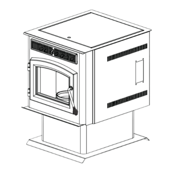
Page 51: Vue D'ensemble De L'installation
10.3.5 VÉRIFICATION DE L'ÉTANCHÉITÉ 10.3.6 NETTOYAGE DE L'ÉVACUATION 10.4 DANS L'ÉVENTUALITÉ OÙ LA VIS SANS FIN BLOQUE 11.0 RECHANGES 12.0 GUIDE DE DÉPANNAGE 13.0 GARANTIE 14.0 HISTORIQUE D'ENTRETIEN 1.0 VUE D’ENSEMBLE DE L’INSTALLATION POÊLE Plaque d'homologation, voir la section « INFORMATION SUR LA PLAQUE Évacuation, voir les sections D’HOMOLOGATION ». -
Page 52: Encastré
ENCASTRÉ Contour, voir la section « INSTALLATION DU CONTOUR ». Évacuation, voir les sections « ÉVACUATION » et « INSTALLATION ». Porte, voir la section « FINITION – INSTALLATION DE LA PORTE VITRÉE ». Plaque d'homologation, voir la section « INFORMATION SUR LA PLAQUE D’HOMOLOGATION ». -
Page 53: Introduction
2.0 INTRODUCTION AVERTISSEMENT • CET APPAREIL EST CHAUD LORSQU’IL FONCTIONNE ET PEUT CAUSER DE GRAVES BRÛLURES EN CAS DE CONTACT . • Ne faites pas fonctionner l’appareil avant d’avoir lu et compris les instructions d’opération. Omettre d’utiliser l’appareil selon les instructions d’opération pourrait causer un incendie ou des blessures. -
Page 54: Dimensions
DIMENSIONS 2.1.1 POÊLE 21 1/4" 540mm 24 1/4" 616mm 30 5/16" 770mm 17" 432mm 11 5/8" 295mm CENTRE DU 23 1/2" 597mm 19 11/16" 500mm CONDUIT CENTRE DE D’ÉVACUATION LA PRISE D’ A IR 2.1.2 ENCASTRÉ (AVEC CONTOUR) 38 3/8" 975mm 29 3/8"... -
Page 55: Spécifications
SPÉCIFICATIONS Contour ajustable 11" (279mm) à 13" (330mm) 10 1/2" (267mm) à 12 1/2" (318mm) Spécifi cations électriques 115 Volts, 3.6 Amps, 60Hz Watts durant la séquence d’allumage 400 (approximativement) Watts durant le fonctionnement 180 (approximativement) Poids Poêle 158 lb (1003kg) / Encastré 140 lb (889kg) Collet d'évacuation 3"... -
Page 56: Information Générale
Nous vous remercions d’avoir choisi le poêle aux granules Wolf Steel ltée. Cet appareil est conçu pour brûler des granules de bois seulement. Veuillez lire le manuel en entier avant d’installer et d’utiliser ce poêle aux granules. Omettre de suivre ces instructions peut entraîner des dommages matériels, des blessures corporelles ou des pertes de vie. -
Page 57: Qualité Des Granules
2.4.2 QUALITÉ DES GRANULES IL EST IMPORTANT DE CHOISIR ET D’UTILISER UNIQUEMENT DES GRANULES SECS, SANS TERRE NI IMPURETÉ TELLE QU’UN CONTENU ÉLEVÉ EN SEL. UN COMBUSTIBLE AVEC DES SALETÉS NUIRA AU BON FONCTIONNEMENT ET À LA PERFORMANCE DE L’APPAREIL ET ANNULERA LA GARANTIE. -
Page 58: Caractéristiques De Sécurité
2015.Non approuvé pour la vente après le 15 mai, 2020 : 40 CFR Part 60, Subpart AAA. MONTH: 3.3 Grammes par heure. WOLF STEEL LTD. TPS35 W385-2035 / A 24 NAPOLEON ROAD, BARRIE, ON, L4M 0G8 CANADA W415-1477 A / 10.19.16... -
Page 59: Planification De L'installation
3.0 PLANIFICATION DE L'INSTALLATION AVERTISSEMENT NE FAITES PAS FONCTIONNER L’APPAREIL AVANT D’AVOIR LU ET COMPRIS LES INSTRUCTIONS D’OPÉRATION. OMETTRE D’UTILISER L’APPAREIL SELON LES INSTRUCTIONS D’OPÉRATION POURRAIT CAUSER UN INCENDIE OU DES BLESSURES. N’UTILISEZ QUE LES ACCESSOIRES OPTIONNELS ET LES PIÈCES DE RECHANGE APPROUVÉS PAR WOLF STEEL POUR CET APPAREIL. -
Page 60: Dégagements Minimaux Aux Matériaux Combustibles
DÉGAGEMENTS MINIMAUX AUX MATÉRIAUX COMBUSTIBLES AVERTISSEMENT NE PAS INSTALLER DANS UN ENDROIT AYANT UNE HAUTEUR DE MOINS DE 48 POUCES (DU PLA- FOND À LA BASE DE L'APPAREIL, EXCLUANT LA HAUTEUR DE L'ÂTRE). 3.4.1 INSTALLATION DROITE Évents verticaux intérieurs Installations à travers un mur avec prise d’air extérieur 3”(76mm) 3”(76mm) 2”... -
Page 61: Protection De Plancher
PROTECTION DE PLANCHER L’appareil doit être installé sur une protection de plancher incombustible se prolongeant sur toute la profondeur de l’appareil et d’au moins 6" (152mm) sur le devant et de chaque côté (épaisseur minimale de 0,018" - calibre 26) des ouvertures d’approvisionnement en combustible et de la chute à cendres. La protection de plancher doit se prolonger sous le raccord en T (si utilisé), de 2"... -
Page 62: Évacuation
4.0 ÉVACUATION TYPE D'ÉVACUATION Vous devez utiliser un évent approuvé de type « L » ou « PL » de 3" (76mm) ou 4" (102mm) de diamètre qui évacue à l'extérieur ou raccorder l'évent à une cheminée préfabriquée de type A à l'aide d'un adaptateur et/ ou une gaine en acier inoxydable pour les installations dans un foyer en maçonnerie. -
Page 63: Terminaison
TERMINAISON La terminaison doit être munie d'un chapeau approuvé (pour empêcher l'eau de s'introduire) ou d'un coude de 45° pointé vers le bas. Si la terminaison est située du côté venteux de la maison, l’utilisation d’un écran protecteur est recommandée pour empêcher la suie de s'accumuler sur le côté... -
Page 64: Exemples D'installation D'évacuation
EXEMPLES D'INSTALLATION D'ÉVACUATION 4.6.1 TERMINAISON HORIZONTALE (À TRAVERS UN MUR) 3” Minimum 12” Minimum Coupe-feu mural 6” Minimum 5’ Maximum Protection 11 5/8” 17” Prise d’air extérieur plancher (Recommandée) 4.6.2 COURSE VERTICALE ET TERMINAISON HORIZONTALE (À TRAVERS UN MUR) Coupe-feu mural Prise d’air extérieur 3”... -
Page 65: Terminaison Verticale
4.6.3 TERMINAISON VERTICALE Chapeau Collet de solin 24”(610mm) Solin de toit L’évacuation doit con- Support à plafond server un dégagement de 3”(76mm) aux matériaux combustibles. 3”(76mm) Protection de 2”(51mm) plancher Prise d’air extérieur (Recommandée) (Illustré l’entrée d’air dans un espace réduit ventilé) 4.6.4 INSTALLATION AVEC UNE CHEMINÉE DE TYPE A Chapeau Collet de solin... -
Page 66: Installation Dans Une Cheminée De Maçonnerie
4.6.5 INSTALLATION DANS UNE CHEMINÉE DE MAÇONNERIE Chapeau de cheminée Chapeau Collet de solin Conduit d’évacuation Couvercle du carneau Té de nettoyage Évacuation 6”(152mm) Protection de plancher Acheminez l’air extérieur au poêle Prise d’air extérieur (Recommandée) W415-1477 A / 10.19.16... -
Page 67: Exemples D'installation D'évacuation De L'encastré
EXEMPLES D’INSTALLATION D’ÉVACUATION DE L’ENCASTRÉ 4.7.1 INSTALLATION TYPIQUE DANS UN FOYER DE MAÇONNERIE EXISTANT AVERTISSEMENT NE RETIREZ AUCUNE BRIQUE OU AUCUN MORTIER DU FOYER. Avant l’installation : Chapeau Chapeau de Lorsque vous installez l’encastré dans un foyer en maçonnerie, Collet de solin cheminée n’enlevez aucune brique ou aucun mortier. -
Page 68: Foyer Préfabriqué
4.7.2 FOYER PRÉFABRIQUÉ Avant l’installation : Vertical Chapeau N’affaiblissez pas la structure, ni ne réduisez la protection des ma- tériaux combustibles en-deçà des exigences du Code national du Storm Collet de bâtiment. Des pièces boulonnées ou vissées ensemble (tablette à Collar solin fumée/défl... -
Page 69: Ossature (Encastré Seulement)
5.0 OSSATURE (ENCASTRÉ SEULEMENT) AVERTISSEMENT RISQUE D’INCENDIE! AFIN D’ÉVITER LA POSSIBILITÉ QUE DE L’ISOLATION OU UN COUPE-VAPEUR ENTRENT EN CON- TACT AVEC L’EXTÉRIEUR DU CAISSON, IL EST CONSEILLÉ D’INSTALLER L’APPAREIL CONTRE DES MURS FINIS (C.-À-D. PANNEAU DE GYPSE) COMME TOUT AUTRE MUR DE LA MAISON. CECI ASSURERA QUE LE DÉGAGEMENT AUX MATÉRIAUX COMBUSTIBLES EST MAINTENU. -
Page 70: Installation Dans Une Enceinte Combustible
INSTALLATION DANS UNE ENCEINTE COMBUSTIBLE AVERTISSEMENT LA PRISE D’AIR EXTÉRIEUR EST OBLIGATOIRE POUR L’INSTALLATION DANS UNE ENCEINTE COMBUSTIBLE. Lorsque vous installez l’encastré comme appareil de chauffage encastré, il est important de vous conformer aux dégagements aux matériaux combustibles. Voir la section « DÉGAGEMENTS MINIMAUX AUX MATÉRIAUX COMBUSTIBLES ». -
Page 71: Dégagements Minimaux De L'enceinte
DÉGAGEMENTS MINIMAUX DE L'ENCEINTE 6 3/8” (162mm) MIN. 2” (51mm) 40” MIN. (1016mm) MIN. 3" (76mm) tout autour (Référez- 27” vous aux directives du fabricant du (686mm) système d’évacuation MIN. 6” 7 1/8” (152mm) (181mm) Protection de plancher 1 7/8” incombustible (48mm) DÉGAGEMENTS MINIMAUX AUX MATÉRIAUX COMBUSTIBLES... -
Page 72: Dégagements Minimaux De La Tablette
DÉGAGEMENTS MINIMAUX DE LA TABLETTE AVERTISSEMENT RISQUE D’INCENDIE. CONSERVEZ TOUS LES DÉGAGEMENTS AUX MATÉRIAUX COMBUSTIBLES SPÉCIFIÉS. NE PAS RESPECTER CES INSTRUCTIONS PEUT CAUSER UN INCENDIE OU UNE SURCHAUFFE. ASSUREZ-VOUS QUE TOUS LES DÉGAGEMENTS (ARRIÈRE, CÔTÉS, DESSUS, ÉVENTS, TABLETTE, FAÇADE, ETC.) SONT RESPECTÉS À LA LETTRE. LORSQUE VOUS UTILISEZ DE LA PEINTURE OU DU VERNIS COMME FINITION POUR VOTRE TABLETTE, ASSUREZ-VOUS QU’ILS SOIENT RÉSISTANTS À... -
Page 73: Finitions
6.0 FINITIONS INSTALLATION DE LA PORTE VITRÉE AVERTISSEMENT LA VITRE PEUT ÊTRE CHAUDE, NE TOUCHEZ PAS LA VITRE JUSQU’À CE QU’ELLE AIT REFROIDI. LES LOQUETS DE PORTE FONT PARTIE D'UN DISPOSITIF DE SÉCURITÉ ET DOIVENT ÊTRE ADÉQUATEMENT VERROUILLÉS. NE FAITES PAS FONCTIONNER L’APPAREIL LORSQUE LES LOQUETS SONT DÉVERROUILLÉS. AVANT D’ENLEVER LA PORTE, ÉTEIGNEZ L’APPAREIL ET ATTENDEZ QUE CE DERNIER SOIT FROID AU TOUCHER. -
Page 74: Installation De La Poignée De Porte
INSTALLATION DE LA POIGNÉE DE PORTE VUE DE FACE PORTE LOQUET DE POIGNÉE DE PORTE RONDELLE ÉCROU DE À RESSORT BLOCAGE ESPACEUR POIGNÉE DE PORTE NOTE : Position du loquet de poignée de porte. PANNEAU DÉCORATIF W415-1477 A / 10.19.16... -
Page 75: Installation Du Contour
INSTALLATION DU CONTOUR Fixez la pièce gauche au côté gauche de l'appareil à l'aide des trois vis fournies. Installez la pièce droite de la même façon. Les panneaux latéraux sont retenus à la chambre de combustion par les trois aimants situés de chaque côté. -
Page 76: Schéma De Câblage
7.0 SCHÉMA DE CÂBLAGE AVERTISSEMENT N’UTILISEZ PAS CE FOYER SI UNE PARTIE QUELCONQUE A ÉTÉ SUBMERGÉE. CONTACTEZ IMMÉDIATEMENT UN TECHNICIEN DE SERVICE QUALIFIÉ POUR INSPECTER L’APPAREIL POUR DES DOMMAGES AU CIRCUIT ÉLECTRIQUE. RISQUE DE CHOCS ÉLECTRIQUES OU D’EXPLOSION. NE BRANCHEZ PAS LE 110 V À LA SOUPAPE OU À... -
Page 77: Instructions De Fonctionnement
8.0 INSTRUCTIONS DE FONCTIONNEMENT CHARGEMENT ADÉQUAT DES GRANULES Avant de charger les granules dans le réservoir, transférez les granules du sac de plastique d’origine à un seau métallique. Gardez à l’esprit que la vis sans fi n s’arrête quand le couvercle est ouvert. Si le couvercle reste ouvert pen- dant plusieurs minutes, le feu pourrait s’éteindre. -
Page 78: Instructions D'allumage
INSTRUCTIONS D'ALLUMAGE Après avoir rempli le réservoir de granules, changez le contrôle au mode manuel afi n d’avoir le plein contrôle jusqu’à ce que vous puissiez vous familiariser avec les fonctions. Ne faites pas fonctionner votre appareil avec la porte vitrée ou le couvercle de réservoir ouverts. Les interrupteurs de sécurité... -
Page 79: Réglages Des Commandes
RÉGLAGES DES COMMANDES RÉGLAGE DE L'ALIMENTATION La vitesse du ventilateur et la vitesse d'alimentation ont été préréglées en usine, mais devront possiblement être ajustées durant l'installation. En raison des variantes (c.-à-d. la grosseur et la longueur de l'évent, la qualité des granules), les préréglages en usine peuvent s'avérer incorrects. Pour éviter que la fl amme ne s'éteigne lorsque réglée à... -
Page 80: Installation D'un Thermostat
INSTALLATION D'UN THERMOSTAT Un thermostat millivolt optionnel est disponible pour vous aider a garder la température de la pièce constante. NOTE: Le thermostat doit être installé par un installateur qualifi é. Débranchez l’alimentation électrique. Enlevez le panneau latéral droit pour avoir accès à l'arrière du panneau de commande. Dénudez et branchez les deux fi... -
Page 81: Entretien
10.0 ENTRETIEN 10.1 QUOTIDIEN (LORSQUE L’APPAREIL EST UTILISÉ) AVERTISSEMENT LE DEVANT DU POÊLE DEVIENT TRÈS CHAUD DURANT LE FONCTIONNEMENT. LAISSEZ LE POÊLE REFROIDIR COMPLÈTEMENT AVANT D’EFFECTUER UN ENTRETIEN. 10.1.1 ENLÈVEMENT DES CENDRES Les cendres doivent être placées dans un contenant métallique avec un couvercle hermétique. Le contenant doit être placé... -
Page 82: Nettoyage Des Tubes D'échangeur De Chaleur
10.1.4 NETTOYAGE DES TUBES D'ÉCHANGEUR DE CHALEUR AVERTISSEMENT LA BORDURE AVANT DU COUVERCLE DU RÉSERVOIR DEVIENT TRÈS CHAUDE. NE TOUCHEZ PAS LA SECTION EN DESSOUS DE LA POIGNÉE. CETTE TIGE DEVIENT TRÈS CHAUDE DURANT LE FONCTIONNEMENT. ATTENDEZ QUE LE POÊLE SOIT COMPLÈTEMENT REFROIDI OU VOUS DEVREZ PORTER DES GANTS ANTICHALEUR LORSQUE VOUS MANIPULEREZ OU NETTOIEREZ CE POÊLE. -
Page 83: Nettoyage Du Brûleur
10.1.6 NETTOYAGE DU BRÛLEUR AVERTISSEMENT ASSUREZ-VOUS QUE LE POÊLE EST COMPLÈTEMENT REFROIDI (ENVIRON 25 MINUTES) AVANT D'OUVRIR LA PORTE ET D'EFFECTUER UN ENTRETIEN. CONDUCTING SERVICE. Pour nettoyer le brûleur, ouvrez la porte et cognez le brûleur afi n d’y déloger les débris. S’il est très bouché, retirez le brûleur afi n d’avoir une meilleure accessibilité. -
Page 84: Tous Les Six Mois (Ou À Chaque Deux Tonnes De Granules)
10.3 TOUS LES SIX MOIS (OU À CHAQUE DEUX TONNES DE GRANULES) AVERTISSEMENT LE CAISSON DEVIENT TRÈS CHAUD DURANT LE FONCTIONNEMENT. LAISSEZ LE POÊLE REFROIDIR COMPLÈTEMENT AVANT D'EFFECTUER UN ENTRETIEN. DÉBRANCHEZ LE CORDON D'ALIMENTATION AVANT D'EFFECTUER UN ENTRETIEN. LA SECTION SUIVANTE EXPLIQUE EN DÉTAIL DES PROCÉDURES D'ENTRETIEN COMPLEXES. NOUS VOUS CONSEILLONS FORTEMENT DE FAIRE FAIRE CET ENTRETIEN PAR UN TECHNICIEN DE SERVICE QUALIFIÉ, POSSIBLEMENT VIA UNE ENTENTE DE SERVICE CONTRACTÉ... -
Page 85: Nettoyage Du Ventilateur D'évacuation
10.3.4 NETTOYAGE DU VENTILATEUR D'ÉVACUATION Note : Ne tentez pas d’effectuer cet entretien sans avoir un joint plat ÉCROUS de rechange pour le moteur du ventilateur d’évacuation. Retirez les six écrous servant à fi xer le moteur du ventilateur d’évacuation. Retirez le moteur en prenant soin de ne pas endommager le fi... - Page 86 10.3.6 NETTOYAGE DE L'ÉVACUATION AVERTISSEMENT LORSQU'UNE PARTIE DU SYSTÈME D'ÉVACUATION EST DÉBRANCHÉE, LES JOINTS DOIVENT ÊTRE SCELLÉS À NOUVEAU AVEC DE LA SILICONE RTV 500°F / 260°C. Le système d’évacuation doit être nettoyé en utilisant Assurez-vous que le chapeau n’est pas bloqué des brosses à...
- Page 87 11.0 RECHANGES AVERTISSEMENT OMETTRE DE POSITIONNER LES PIÈCES CONFORMÉMENT À CE MANUEL OU D’UTILISER UNIQUEMENT DES PIÈCES SPÉCIFIQUEMENT APPROUVÉES POUR CET APPAREIL PEUT CAUSER DES DOMMAGES MATÉRIELS OU DES BLESSURES CORPORELLES. Contactez votre détaillant pour les questions concernant les prix et la disponibilité des pièces de rechange.
- Page 88 COMPOSANTS COMMUNS RÉF N° DE PIÈCE DESCRIPTION W715-0843-SER PANNEAU DÉCORATIF W225-0258 PORTE NOIRE W430-0013 AIMANTS DE PORTE W325-0018-SER POIGNÉE DE PORTE W320-0002 LOQUET DE POIGNÉE DE PORTE W285-0002 FUSE, 2 AMP W285-0001 FUSE, 5 AMP ACCESSOIRES RÉF N° DE PIÈCE DESCRIPTION 114KT PRISE D’AIR EXTÉRIEUR - 5 PI / 1.5m (2"...
- Page 89 12.0 GUIDE DE DÉPANNAGE AVERTISSEMENT COUPEZ L’ALIMENTATION EN GAZ ET L’ALIMENTATION ÉLECTRIQUE AVANT DE PROCÉDER À L’ENTRETIEN DE L’APPAREIL. L’APPAREIL PEUT ÊTRE CHAUD. ATTENDEZ QU’IL SOIT REFROIDI AVANT D’EN FAIRE L’ENTRETIEN. N’UTILISEZ PAS DE PRODUITS ABRASIFS. LORSQUE VOUR VÉRIFIEZ DES CONNEXION, QUE VOUS INSTALLEZ DES FILS DE DÉRIVATIONS (POUR EFFECTUER DES TESTS UNIQUEMENT) OU QUE VOUS REMPLACEZ DES COMPOSANTS, DÉBRANCHEZ L’APPAREIL DU RÉCEPTACLE AFIN D’ÉVITER LES CHOCS ÉLECTRIQUES OU DES DOMMAGES AUX COMPOSANTS.
- Page 90 PROBLÈME SOLUTIONS Le moteur de la Le couvercle du réservoir doit être fermé. vis sans fi n ne fonc- Assurez-vous que le ventilateur d’évacuation fonctionne. tionne pas normale- Vérifi ez l’état du boyau d’évacuation (situé sur le côté gauche de l’appareil). Il ne doit pas ment.
- Page 91 PROBLÈME SOLUTIONS L’appareil s’éteint En raison des différents types d’installation, des longueurs et des grandeurs de conduits et de la constamment. qualité des granules, le réglage d’alimentation minimal préréglé en usine peut s’avérer incorrect. Il est possible que vous deviez expérimenter avec la vitesse d’alimentation et le contrôle d’air. Si l’appareil s’éteint en laissant des granules non consumés ou des cendres semblables à...
- Page 92 13.0 GARANTIE Les produits TIMBERWOLF sont fabriqués conformément aux normes strictes du Certifi cat d’Assurance de Qualité ISO 9001 : 2000 mondialement reconnu. Les produits TIMBERWOLF sont conçus avec des composants et des matériaux de qualité supérieure, assemblés par des artisans qualifi és qui sont fi ers de leur travail. Une fois assemblé, chaque appareil est soigneusement inspecté...
- Page 93 14.0 HISTORIQUE D'ENTRETIEN 43.1A W415-1477 / A / 10.19.16...
- Page 94 15.0 NOTES 44.1 W415-1477 A / 10.19.16...
- Page 95 44.1 W415-1477 / A / 10.19.16...
- Page 96 napoleonproducts.com...