
Manuels Connexes pour Siemens The PROBE


Sommaire des Matières pour Siemens The PROBE
- Page 1 Instruction Manual December 2008 English Deutsch Español Français the probe LEVEL TRANSMITTER...
- Page 2 THE PROBE Ultrasonic Level Transmitter Part #: Serial #: Power Rating: 12-30 V , 0.1A Max Operating Temp: – 40°C to 60°C Enclosure: IP65 / NEMA 4X / TYPE 4 Class I & II, Div 1 Group A, B, C, D, E, F, G Per Dwg.: 1-8600016Z-DX-A...
- Page 3 Installation Environmental The Probe should be mounted in an area that is within the temperature range specified and that is suitable to the housing rating and materials of construction. The front lid should be accessible to allow programming, wiring and display viewing.
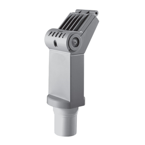
- Page 4 Mounting Mount the Probe so that the face of the sensor is at least 25 cm above the highest Note: anticipated level. Threaded hinged lid The Probe is available in three 7 mm 34 mm (0.3”) (3.3”) thread types: 2” NPT, 2” BSP or max.
-
Page 5: Cable Entry
Sanitary Ferrule,4" FDA Approved The Probe • mount The Probe onto the top of (US Food and Drug Administration) the tank’s sanitary ferrule • secure mating by surrounding clamp* the joint with the clamp adjusting • tighten adjusting wing nut... - Page 6 Note: Reference drawing 1-8600016Z-DX-A is available on the product page of our website at www.siemens.com/theprobe. Go to More Info / Installation drawings and scroll to Connection Drawings. Under the entity evaluation concept, The Probe has the following characteristics : Vmax = 30 V DC Imax = 200 mA dc...
- Page 7 Hazardous Area 4 to 20 mA 4 to 20 mA load see terminal connection table N / L2 MTL 2441 / 120V & 240 V Power supply input is reverse polarity protected. Note: 7ML19985GC62 The Probe – INSTRUCTION MANUAL Page 5...
- Page 8 Non Intrinsically Safe The Probe loop instrumentation R max R max = V supply – 12 V 20 mA V supply 12 to 30 V DC Power supply is reverse polarity protected. Note: Page 6 The Probe – INSTRUCTION MANUAL 7ML19985GC62...
- Page 9 • Press the key a second time to set the new distance reference. • After viewing or calibrating, Probe operation automatically reverts to the Run mode (6 sec). The calibration value is referenced from the face of The Probe sensor, in the units displayed. 4 mA calibration Press “4”...
- Page 10 Refer to Troubleshooting on page 12. Adjustments There are several operating adjustments that can be made to The Probe. To access the operating adjustments, simultaneously press the "4" and "20" keys until the desired adjustment is obtained. A viewing sequence of the stored value is automatically initiated. During this time the value can be changed by pressing either the "4"...
- Page 11 “20” to increase blanking i.e. 0.36 m the key depressed during the blanking adjustment and release press “4” to decrease to desired blanking when desired value is obtained. value i.e. 0.35 m new blanking value 6 sec 7ML19985GC62 The Probe – INSTRUCTION MANUAL Page 9...
- Page 12 The Probe will be able to keep up with rates of change. If The Probe measurement cannot keep up with the rate of level change, set the adjustment from `1' to `2'. If The Probe still cannot keep up with the rate of level change, set the adjustment option to `3'.
- Page 13 • When the desired option is displayed, stop pressing the key. The display will automatically return to the Run mode (6 sec). units 3 sec current option i.e. m Press “20” for option 2 i.e. ft option 2 selected 6 sec 7ML19985GC62 The Probe – INSTRUCTION MANUAL Page 11...
- Page 14 Supplement Measurement Interval mA loop current Troubleshooting The echo is not reliable and The Probe is waiting for a valid echo before updating the measurement. Probable causes are: • material or object in contact with sensor face • The Probe is too close to the fill point •...
- Page 15 22 mm (0.87") dia. `knock out' for conduit entrance, 2 places 2 screw terminal block for 2.5 mm (14 ga) solid wire / 1.5 mm (16 ga) stranded wire max Enclosure Rating: • Type 4 / NEMA 4X / IP65 7ML19985GC62 The Probe – INSTRUCTION MANUAL Page 13...
- Page 16 • Intrinsically safe CSA, FM, intrinsically safe for Class I and II, Div. 1, GR. A, B, C, D, E, F, G hazardous location ATEX II 1G, BAS99ATEX1300 INMETRO: Br-Ex ia IIC T4 Page 14 The Probe – INSTRUCTION MANUAL 7ML19985GC62...
-
Page 17: Montage
Im Gehäuse ist der Ultraschallsensor und der Temperaturfühler untergebracht. Der Probe sendet Ultraschallimpulse aus, die vom zu messenden Material reflektiert werden. Die Echos werden vom Sensor erfasst und mit der bewährten 'Sonic Intelligence' von Siemens Milltronics ausgewertet. Filter ermöglichen die Unterscheidung von Störechos, die durch akustisches oder elektrisches Rauschen und Rührwerke entstehen, vom Nutzecho des Materials. - Page 18 87 mm Montage- (3.4") ø Achten Sie auf die Kompatibilität der gewinde chemischen Reinigungsmittel mit Sensor 76 mm integrierter (2.9") Dichtungs- PVDF. ring 53 mm 61 mm (2. 1 ") (2.4") ø max. Seite 2 The Probe – BETRIEBSANLEITUNG 7ML19985GC62...
- Page 19 B. Schraube lösen und Deckel öffnen. C. Kabel einführen. D. Kabel für die Schleife anschließen. E. Deckel schließen. Max. Drehkraft 1,1 bis 1,7 N-m (10 bis 15 in-lb). Systemdiagramm Stromschleifen- The Probe system 7ML19985GC62 The Probe – BETRIEBSANLEITUNG Seite 3...
- Page 20 Eigensichere Ausführung FM (Bezugszeichnung 1-8600016Z-DX-A) Hinweis: Die Bezugszeichnung Nr. 1-8600016Z-DX-A finden Sie auf der Produktseite unserer Webseite unter www.siemens.com/theprobe. Siehe More Info / Installationshinweise und blättern Sie auf Anschlusszeichnungen. Im Rahmen des gesamtheitlichen Bewertungskonzepts weist der Probe folgende Merkmale auf:...
- Page 21 AC Verstärker Sicherer Bereich Ex-gefährdeter Bereich 4 bis 20 mA 4 bis 20 mA Bürde siehe Anschluss- tabelle N / L2 MTL 2441 / 120V & 240 V Der Spannungseingang ist verpolungsgeschützt. Hinweis: 7ML19985GC62 The Probe – BETRIEBSANLEITUNG Seite 5...
- Page 22 Stycast 2075 ist eine Marke von Emmerson and Cummings Nicht Eigensicher The Probe Stromschleife R max R max = V Versorgung – 12 V 20 mA V Versorgung 12 bis 30 V DC Der Spannungseingang ist verpolungsgeschützt. Hinweis: Seite 6 The Probe – BETRIEBSANLEITUNG 7ML19985GC62...
- Page 23 • Der kalibrierte Wert bezieht sich auf die Sendefläche des Probe in der angezeigten Maßeinheit. 4 mA Abgleich Taste “4” Taste “4” erneut 4 mA Abgleich drücken Abgleich ungültig, bei neuer 4 mA Abgleich wiederholen 7ML19985GC62 The Probe – BETRIEBSANLEITUNG Seite 7...
- Page 24 Taste "20" erhöht und mit der Taste "4" verringert werden. Drücken Sie die entsprechende Taste solange, bis der gewünschte Wert erreicht ist. Die Anzeige kehrt automatisch wieder in den Run Modus zurück (6 Sek.). Seite 8 The Probe – BETRIEBSANLEITUNG 7ML19985GC62...
- Page 25 Werte kann Bsp. 0,36 m beschleunigt werden, indem Sie die jeweilige Taste gedrückt Taste “4” zur Verringerung der halten, bis der gewünschte Wert Ausblendung, Bsp. 0,35 m erreicht ist. Neuer Ausblendungswert 6 Sek. 7ML19985GC62 The Probe – BETRIEBSANLEITUNG Seite 9...
- Page 26 • Um die Failsafe-Funktion zu ändern, ist die 'FLS' Anzeige aufzurufen. • Mit der Taste "20" können die Optionen (1-2-3) durchlaufen werden. Um die Optionen rückwärts zu durchlaufen (3-2-1), wird die Taste "4" gedrückt. Seite 10 The Probe – BETRIEBSANLEITUNG 7ML19985GC62...
- Page 27 • Drücken Sie die jeweilige Taste solange, bis die gewünschte Option erscheint. Die Anzeige kehrt automatisch wieder in den Run Modus zurück (6 Sek.). Einheit 3 Sek. Aktuelle Option, Bsp. m Taste “20” für Option 2 Bsp. ft Option 2 gewählt 6 Sek. 7ML19985GC62 The Probe – BETRIEBSANLEITUNG Seite 11...
- Page 28 • U.S.A.: 07/858/707 • Deutschland: M92022723 • U.K.: 2021748 • Frankreich: 921873 • Japan: 966217 Elektronik / Sensor: • U.S.A.: 5,267,219 5,339,292 • U.K.: 2,260,059 • Patentierte Applikationen in U.K., Kanada, Europa, Afrika, Australien Seite 12 The Probe – BETRIEBSANLEITUNG 7ML19985GC62...
-
Page 29: Technische Daten
Klappdeckel 2 Kabeleinführungen (Blindverschluss) 22 mm (0,87") Durchmesser 2 Klemmen für max. 2,5 mm (14 ga) Massivleiter / max. 1,5 mm (16 ga) Litze Gehäuseschutzart: • Typ 4 / NEMA 4X / IP65 7ML19985GC62 The Probe – BETRIEBSANLEITUNG Seite 13... - Page 30 • 3A (Nicht Eigensicher, nur Sanitärausführung) • Eigensicherheit CSA, FM, eigensicher für Klasse I & II, Div. 1, GR. A, B, C, D, E, F, G Ex-gefährdeter Bereich ATEX II 1 G, BAS99ATEX1300 INMETRO: Br-Ex ia IIC T4 Seite 14 The Probe – BETRIEBSANLEITUNG 7ML19985GC62...
-
Page 31: Condiciones Ambientales
The Probe debe ser utilizado únicamente de la manera que se especifica en este manual. The Probe es un transmisor de nivel ultrasónico que combina un sensor y una parte electrónica en un cuerpo único. Está diseñado para medir niveles de líquidos en depósitos abiertos o cerrados. El sensor se fabrica en PVDF o ETFE lo que lo hace adecuado para una amplia variedad de industrias. - Page 32 Montaje Montar The Probe de forma que la cara del transductor esté por lo menos 25 cm por Nota: encima del máximo nivel posible. Con rosca Tapa abatible The Probe está disponible con tres tipos de rosca: 2" NPT, 2" BSP ó...
-
Page 33: Diagrama Del Sistema
Férula sanitaria 4" The Probe certificada por la FDA* • The Probe se fija por encima de la férula sanitaria del depósito • El sistema se fija con la Abrazadera* abrazadera y... Tuerca mariposa • Se aprieta la tuerca mariposa. - Page 34 Nota: El diagrama ref. 1-8600016Z-DX-A está disponible en la sección Productos de nuestra web, www.siemens.com/theprobe. Consulte la sección More Info / Installation drawings, Connection Drawings. En conformidad con el concepto de evaluación de entidad, The Probe tiene las siguientes especificaciones: Vmáx = 30 V DC Imáx = 200 mA DC...
- Page 35 4 a 20 mA 4 a 20 mA Carga Ver tabla de conexiones N / L2 MTL 2441 / 120 V & 240 V Protección del suministro eléctrico (alimentación) contra polaridad invertida. Nota: 7ML19985GC62 The Probe – MANUAL DE INSTRUCCIONES Página 5...
- Page 36 Directrices generales relativas al sistema The Probe, modelo seguridad intrínseca, conforme con el certificado Tipo CE BAS99ATEX1300 El aparato puede ser utilizado en zonas con gases y vapores inflamables, con aparatos del Grupo IIC y clase de temperatura T4. El sistema puede soportar temperaturas ambientes de –40 C a +60 El aparato no se ha analizado como sistema de protección, como se indica en la Directiva 94/9/...
-
Page 37: Puesta En Marcha
• Se puede efectuar la calibración de la distancia pulsando de nuevo la tecla correspondiente. • Después de la visualización o calibración, The Probe vuelve automáticamente al modo Run (6 segundos). El valor de calibración se calcula desde la cara del transductor, en las unidades visualizadas. - Page 38 Cuando se recibe el eco válido, el usuario visualiza `Bueno'. Véase Solución de fallos, página 12. Ajustes Se pueden efectuar varios ajustes para conseguir un nivel de operación óptimo de The Probe. Pulsar simultáneamente las teclas "4" y "20" hasta visualizar el ajuste deseado. Se visualiza automáticamente el valor almacenado.
- Page 39 Ejemplo: 0.36 m durante el ajuste de la zona Pulsar “4” para decrementar la zona muerta y soltarla cuando se muerta. Ejemplo: 0.35 m obtenga el valor deseado. Zona muerta seleccionada 6 seg. 7ML19985GC62 The Probe – MANUAL DE INSTRUCCIONES Página 9...
- Page 40 Si éste valor no se adapta a los cambios de nivel de material, cambiar el ajuste de ‘1' a `2'. Si The Probe sigue sin responder al cambio de nivel, seleccionar la opción ‘3'. Se recomienda no seleccionar una opción que sea demasiado rápida para la aplicación.
- Page 41 • Al visualizar la opción deseada, soltar la tecla. El display / indicador vuelve automáticamente al modo Run (6 segundos). Unidades 3 seg. Opción actual, ejemplo: m Pulsar “20” , opción 2. Ejemplo: ft Opción 2 seleccionada 6 seg. 7ML19985GC62 The Probe – MANUAL DE INSTRUCCIONES Página 11...
-
Page 42: Solución De Fallos
Intervalo de medición Lazo mA Solución de fallos El eco no es fiable. The Probe espera un eco válido antes de actualizar la medición. Causas probables: • Material u objeto en contacto con la cara del transductor • The Probe está demasiado cerca del punto de llenado •... -
Page 43: Alimentación Eléctrica
Especificaciones Alimentación eléctrica: • 12 a 30 V DC (The Probe), máximo 0,1 A • Corriente de bucle máximo 4 a 20 mA Condiciones ambientales: • Ubicación: interior / exterior • Altitud: máx. 2000 m • Temperatura contínua: -40 a +60°C (-40 a +140°F) ambiente: -20°C (-5°F) con montaje metálico... - Page 44 • Seguridad intrínsecaCSA, FM, seguridad intrínseca para Clase I & II, Div. 1, GR. A, B, C, D, E, F, G zona peligrosa ATEX II 1 G, BAS99ATEX1300 INMETRO: Br-Ex ia IIC T4 Página 14 The Probe – MANUAL DE INSTRUCCIONES 7ML19985GC62...
-
Page 45: Caractéristiques Environnementales
à nouveau par le transducteur sous forme d’écho. Chaque écho est analysé par Le Probe. Cette unité intègre les techniques brevetées Sonic Intelligence Siemens Milltronics, pour l’extraction d’écho. Un filtre permet de différencier l’écho réel de ceux générés par des bruits électriques et acoustiques, et les pales d’agitateur en mouvement. -
Page 46: Raccord Fileté
Montage Le Probe doit être installé de telle sorte que la face émettrice du capteur soit située au Note : moins 25 cm au dessus du niveau attendu le plus haut. Raccord fileté couvercle à charnière L’unité est disponible en trois versions de filetage : 2"... -
Page 47: Connexions
Col sanitaire 4", approuvé Le Probe par la FDA • Installer Le Probe sur la virole (ou col évasé) du réservoir. • Serrer à l’aide du collier de collier de serrage* serrage. vis de • Serrer la vis de serrage. serrage virole réservoir... -
Page 48: Connexions Sécurité Intrinsèque
FM (schéma de référence 1-8600016Z-DX-A) N.B. : Le schéma de référence 1-8600016Z-DX-A est disponible sur la page produit de notre site web www.siemens.com/theprobe. Consulter la rubrique More Info / Installation drawings, Connection Drawings. Suivant le concept d'évaluation d'entité, Le Probe a les caractéristiques siuvantes :... -
Page 49: Connexion
Barrière Connexion Fabricant Réf. produit Bornier Le Probe 787s+ 706+ 9002 / 13- STAHL 280-110-00 9001 / 51- STAHL 280-110-14 Répétiteur CC Sécurité Zone dangereuse 4 à 20 mA 4 à 20 mA charge voir tableau de connexion bornier alimentation 20 à... -
Page 50: Version Standard
Consignes générales applicables aux système Probe Sécurité Intrinsèque, attestation d’examen CE de Type CE BAS99ATEX1300 Le système peut être utilisé en présence de gaz et de vapeurs enflammables, avec des appareils du Groupe IIC, et classification de température T4. Le système peut être utilisé dans une plage de température ambiante de –40 C à... -
Page 51: Fonctionnement
Fonctionnement Mise en service mode programmation alphanumérique • Le Probe étant correctement installé (ou orienté vers un mur à une distance de 0.25 touche à 5 m), effectuer sa mise sous tension. ‘20’ • L’afficheur du Probe indique initialement ... unités touche ‘4’... -
Page 52: Etats De Fonctionnement
Etalonnage 20 mA Presser “20” Presser “20” à Etalonnage 20 mA nouveau Recommencer ! Nouvelle référence 20 mA = étalonnage incomplet L’étalonnage peut être effectué sans tenir compte du temps de réponse de la mesure. Note : Etats de fonctionnement La zone graphique de l’afficheur permet de visualiser les états de fonctionnement de l’unité... -
Page 53: Zone Morte
Etalonnage 4 mA Etalonnage 4 mA initialisé Visualisation de la distance programmée pour la sortie 4 mA. Exemple : 4.50 m Presser”20” pour incrémenter jusqu’à 4.60 m par exemple Nouvelle valeur Etalonnage 20 mA Etalonnage 20 mA initialisé Pour une visualisation plus Note : Visualisation de la distance programmée rapide des valeurs, maintenir la... -
Page 54: Temps De Réponse
Temps de réponse Le réglage du temps de réponse permet à l’utilisateur de régler plusieurs paramètres de fonctionnement simultanément. Réponse de Correspond à la capacité de l’unité Probe à s’adapter aux vitesses de variation de niveau du mesure : matériau mesuré. Si Le Probe ne peut pas s’adapter aux vitesses de variation de niveau, modifier le réglage de `1' à... -
Page 55: Temporisation Sécurité-Défaut
• Cesser de presser la touche dès que l’option souhaitée est affichée. L’affichage revient automatiquement en mode Run (6 secondes). Sécurité-défaut 3 sec Option sélectionnée, exemple : plein Presser “20” pour l’option 2, exemple : vide Option 2 sélectionnée 6 sec Temporisation sécurité-défaut La temporisation sécurité-défaut permet à... -
Page 56: Intervalle De Mesure
Supplément Intervalle de mesure mA courant de boucle Dépistage des défauts L’écho reçu n’est pas fiable. Le Probe attend de recevoir un écho valide avant de rafraîchir la mesure. Les causes probables sont : • Matériau ou cible en contact avec la face émettrice du capteur •... -
Page 57: Caractéristiques Techniques
Caractéristiques Techniques Alimentation : • 12 à 30 V CC (Probe), 0.1 A maximum • courant de boucle 4 à 20 mA maximum Caractéristiques environnementales : • montage : en intérieur / extérieur • altitude : 2000 m maximum • température continue: -40 à... - Page 58 Poids : • 1.5 kg (3.3 lb) Homologations : • CE, C-TICK (Rapport de performance CEM disponible sur demande) • 3A (version pour process sanitaire, standard uniq.) • sécurité intrinsèque CSA, FM, sécurité intrinsèque pour zones dangereuses Class I & II, Div. 1, GR.
- Page 60 Siemens Milltronics Process Instruments Inc. Siemens Milltronics Process Instruments Inc. 2008 1954Technology Drive, P .O. Box 4225 Subject to change without prior notice Peterborough, ON, Canada K9J 7B1 Rev. 2.0 Tel: (705) 745-2431 Fax: (705) 741-0466 *7ml19985GC62* Email: techpubs.smpi@siemens.com...