Table des Matières
Publicité
Les langues disponibles
Les langues disponibles
Liens rapides
Betriebsanleitung
Operating instructions
Notice technique
Instrukcja eksploatacji
Basismodul
Base module
Module de base
Moduł podstawowy
Copyright 2021 AFRISO-EURO-INDEX GmbH. Alle Rechte vorbehalten.
Lindenstraße 20
74363 Güglingen
Telefon +49 7135 102-0
Service +49 7135 102-211
Telefax +49 7135 102-147
info@afriso.com
www.afriso.com
Version: 04.2021.0
ID: 900.000.0623
Publicité
Table des Matières

Manuels Connexes pour afriso CosiTherm BM


Sommaire des Matières pour afriso CosiTherm BM
- Page 1 Betriebsanleitung Operating instructions Notice technique Instrukcja eksploatacji Basismodul Base module Module de base Moduł podstawowy Copyright 2021 AFRISO-EURO-INDEX GmbH. Alle Rechte vorbehalten. Lindenstraße 20 74363 Güglingen Telefon +49 7135 102-0 Service +49 7135 102-211 Telefax +49 7135 102-147 info@afriso.com www.afriso.com Version: 04.2021.0...
- Page 2 Betriebsanleitung Basismodul Produktfamilie CosiTherm® Typ: BM Copyright 2021 AFRISO-EURO-INDEX GmbH. Alle Rechte vorbehalten. Lindenstraße 20 74363 Güglingen Telefon +49 7135 102-0 Service +49 7135 102-211 Telefax +49 7135 102-147 info@afriso.com Version: 04.2021.0 www.afriso.com ID: 900.000.0623...
- Page 3 Über diese Betriebsanleitung Über diese Betriebsanleitung Diese Betriebsanleitung beschreibt das Basismodul „BM“ (im Folgenden auch „Produkt“). Diese Betriebsanleitung ist Teil des Produkts. • Sie dürfen das Produkt erst benutzen, wenn Sie die Betriebsanleitung vollständig gelesen und verstanden haben. • Stellen Sie sicher, dass die Betriebsanleitung für alle Arbeiten an und mit dem Produkt jederzeit verfügbar ist.
- Page 4 Informationen zur Sicherheit Informationen zur Sicherheit Warnhinweise und Gefahrenklassen In dieser Betriebsanleitung finden Sie Warnhinweise, die auf potenzielle Gefahren und Risiken aufmerksam machen. Zusätzlich zu den Anweisungen in dieser Betriebsanleitung müssen Sie alle am Einsatzort des Produktes geltenden Bestimmungen, Normen und Sicherheitsvorschriften beachten. Stellen Sie vor Verwendung des Produktes sicher, dass Ihnen alle Bestim- mungen, Normen und Sicherheitsvorschriften bekannt sind und dass sie befolgt werden.
-
Page 5: Informationen Zur Sicherheit
Informationen zur Sicherheit Bestimmungsgemäße Verwendung Das Basismodul ist ein Teil der CosiTherm®. Dieses Produkt eignet sich aus- schließlich zur Regelung (Heizen/Kühlen) der Raumtemperatur von Einzel- räumen mit Fußbodenheizung. Eine andere Verwendung ist nicht bestimmungsgemäß und verursacht Gefahren. Stellen Sie vor Verwendung des Produkts sicher, dass das Produkt für die von Ihnen vorgesehene Verwendung geeignet ist. -
Page 6: Transport Und Lagerung
Transport und Lagerung Qualifikation des Personals Arbeiten an und mit diesem Produkt dürfen nur von Fachkräften vorgenom- men werden, die den Inhalt dieser Betriebsanleitung und alle zum Produkt gehörenden Unterlagen kennen und verstehen. Die Fachkräfte müssen aufgrund ihrer fachlichen Ausbildung, Kenntnisse und Erfahrungen in der Lage sein, mögliche Gefährdungen vorherzusehen und zu erkennen, die durch den Einsatz des Produkts entstehen können. - Page 7 Produktbeschreibung Produktbeschreibung Übersicht über die einzelnen CosiTherm® Komponenten Komponente Varianten Erklärung Basismodul Uhrmodul Uhr-Funkmodul Mit interner Antenne Mit externer Antenne Raumfühler Draht Funk, Temperatur Funk, Temperatur und Feuchte Reglermodul Draht mit 2 Regelkreisen Draht mit 6 Regelkreisen Funk mit 2 Regelkreisen Funk mit 6 Regelkreisen Mit externer Antenne und 2 Regelkreisen Mit externer Antenne und 6 Regelkreisen...
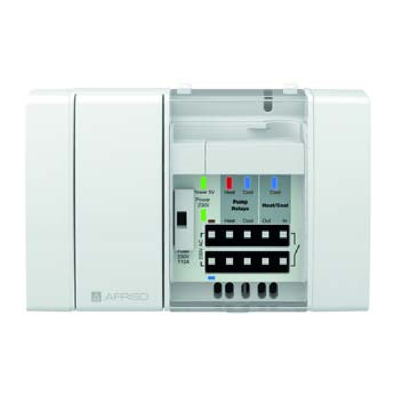
- Page 8 Produktbeschreibung Übersicht A. Sicherungsfach B. Betrieb Netzspannung (LED grün) C. Betrieb 5 V (LED grün) D. Pumpe Heizen (LED rot) E. Pumpe Kühlen (LED blau) F. Kühlen (LED blau) G. Eingang Umschaltung Heizen/Kühlen H. Kaskadier-Ausgang Relais Heizen/Kühlen I. Relaiskontakt Pumpe Kühlen J.
-
Page 9: Anwendungsbeispiele
Produktbeschreibung Anwendungsbeispiel(e) Abbildung 1: Basismodul, Reglermodul, Uhrmodul, Raumfühler D und Stellantriebe Abbildung 2: Basismodul, Reglermodul F, Uhrmodul, Raumfühler F, externer Antenne und Stellantriebe... -
Page 10: Zulassungsdokumente, Bescheinigungen, Erklärungen
Produktbeschreibung Abbildung 3: Basismodul mit Uhr-Funkmodul und externer Antenne Funktion Die CosiTherm® ist eine Einzelraum-Temperaturregelung und regelt die Temperatur von Räumen mit Fußbodenheizung (Heizen/Kühlen). Zentraler Baustein von CosiTherm® ist das Basismodul. An das Produkt können die Reglermodule angeschlossen werden. Das Produkt versorgt über die Reglermodule die Raumfühler D mit 5 V DC und die thermischen Stellantriebe mit 230 V AC. - Page 11 Produktbeschreibung Technische Daten Parameter Wert Allgemeine Daten Abmessungen Gehäuse 122 x 92 x 45 mm (B x H x T) Gewicht 215 g Werkstoff Gehäuse PC/ABS Farbe Hellgrau, ähnlich RAL 7047 Temperatureinsatzbereich Umgebung -20 ... 60 °C Lagerung -20 ... 60 °C Max.
- Page 12 Produktbeschreibung *) Hinweis AFRISO empfiehlt die Verwendung von AFRISO Stellantrieben zur Sicher- stellung der optimalen Systemleistung. Wenn Stellantriebe anderer Herstel- ler verwendet werden, müssen folgende Grenzwerte eingehalten werden: Betriebsspannung AC 230 V ±10 %, 50/60 Hz max. Betriebsstrom 9 mA max.
-
Page 13: Montage Des Produkts
Montage Montage Montageort Das Produkt (CosiTherm®) muss in der Nähe des Heizkreisverteilers mon- tiert werden. Montage des Produkts Stellen Sie sicher, dass das Produkt spannungsfrei ist 1. Öffnen Sie die Abdeckung mit Hilfe eines Schrau- bendrehers. 2. Ziehen Sie die Abschluss- kappe ab. - Page 14 Montage 3. Verbinden Sie das/die Reglermodul(e) mit dem Produkt und sichern bei- des mit der Verriegelung. 4. Setzten Sie die Abschlussklappe auf das letzte Reglermodul.
-
Page 15: Elektrischer Anschluss
Montage 5. Hängen Sie die Abde- ckung ein und schließen diese. Elektrischer Anschluss GEFAHR ELEKTRISCHER SCHLAG • Stellen Sie sicher, dass durch die Art der elektrischen Installation der Schutz gegen elektrischen Schlag (Schutzklasse, Schutzisolierung) nicht vermin- dert wird. Nichtbeachtung dieser Anweisungen führt zu Tod oder schweren Verlet- zungen. - Page 16 Montage GEFAHR ELEKTRISCHER SCHLAG DURCH SPANNUNGSFÜHRENDE TEILE • Unterbrechen Sie vor Beginn der Arbeiten die Netzspannung und sichern Sie diese gegen Wiedereinschalten. • Stellen Sie sicher, dass durch elektrisch leitfähige Gegenstände oder Medien keine Gefährdungen ausgehen können. Nichtbeachtung dieser Anweisungen führt zu Tod oder schweren Verlet- zungen.
-
Page 17: Anschlussschema
Montage 5.3.1 Anschlussschema A. AC 230 V Versorgung B. Eingang Heizen/Kühlen offen: - Heizen geschlossen: Kühlen interne Steuer- spannung: DC 5 V C. Kaskadierausgang poten- zialfreier Relaiskontakt max. AC 250 V, 3 A max. DC 30 V, 3 A D. - Page 18 Montage 5.3.3 Kabelklemme anbringen 1. Fixieren Sie das Kabel auf der Rückseite des Reglermoduls mit der Kabelklemme (A). Wenn Raumfühler mit Drahtanschluss eingesetzt werden, bringen Sie die Kabelklemme erst nach dem elektrischen Anschluss des Raumfühlers an.
- Page 19 Montage 2. Verfahren Sie mit allen weiteren Kabeln gleich. 3. Die Kabelklemmen können auch wieder gelöst werden. Heben Sie die beiden Laschen (2) nach außen an und nehmen die Kabel- klemme ab. Modul auf Hutschiene montieren Stellen Sie sicher, dass alle Module (Basis- und Reglermodul) zusam- mengesteckt und fest verriegelt sind.
- Page 20 Montage Module von der Hutschiene abnehmen 1. Heben Sie die Module (Basis- und Reglermodul) leicht an und nei- gen Sie die Module oben von der Hutschiene weg. 2. Nehmen Sie die Module (Basis- und Reglermodul) nach unten weg.
- Page 21 Montage Nachrüstung des Uhr-Funkmoduls HINWEIS ELEKTROSTATISCHE ENTLADUNG • Erden Sie sich immer, bevor Sie die elektronischen Bauteile berühren. • Berühren Sie beim Einsetzen nicht das Produkt, sondern setzen Sie es mit Hilfe der anti-elektrostatischen Folie in den Steckplatz ein. Nichtbeachtung dieser Anweisungen kann zu Sachschäden führen. ...
- Page 22 Montage 3. Bringen Sie die Abdeckung an und lassen Sie diese einrasten. 4. Befestigen Sie die Antenne, wie dargestellt, an dem Uhr-Funkmo- dul. Externen Antenne montieren 5.7.1 Klebe-Antenne Leistungsgewinn: 2 dbi...
- Page 23 Montage 1. Öffnen/entfernen Sie die Abde- ckung des Verteilerschranks. 2. Bohren Sie mit einer Bohrma- schine ein Loch in die Innenseite des Verteilerschranks. 3. Ziehen Sie das Kabel durch das gebohrte Loch und schrauben Sie den Anschluss der Klebe- Antenne am Uhr-Funkmodul an. 4.
- Page 24 Montage 5.7.2 Antenne SMA-Winkelstecker und Koaxialkabel Leistungsgewinn: 3,5 dbi 1. Öffnen/entfernen Sie die Abde- ckung des Verteilerschranks. 2. Bohren Sie mit einer Bohrma- schine ein Loch in die Abdeckung des Verteilerschranks.
- Page 25 Montage 3. Schrauben Sie das eine Ende des Koaxialkabels am Uhr-Funkmodul 4. Lösen Sie am anderen Endes des Koaxialkabels die Kontermutter und führen Sie den Anschluss durch das gebohrte Loch. 5. Schrauben Sie die Kontermutter von der Außenseite an. 6. Schließen Sie die Abdeckung des Verteilerschranks.
- Page 26 Betrieb Betrieb Übersicht der LED-Signale C D E Anzeige Zustand Erklärung Betrieb Netz- Leuchtet Wenn Netzspannung AC 230 V vorhanden spannung Erlischt Bei Ausfall der Netzspannung (LED grün) Bei Ausfall der Sicherung (1) Betrieb 5 V Leuchtet Wenn 5 V Versorgung vorhanden (LED grün) Erlischt Bei Ausfall der Netzspannung...
- Page 27 (LED grün) nungsversorgung Sicherung defekt Prüfen Sie die Siche- rung Netzteil defekt Bitte wenden Sie sich an die AFRISO-Service Hotline Sonstige Störungen Bitte wenden Sie sich an die AFRISO-Service Hotline Netzsicherung tauschen Stellen Sie sicher, dass die Netzspannung unterbrochen und gegen Wie- dereinschalten gesichert ist.
- Page 28 Störungsbeseitigung 2. Nehmen Sie den Sicherungshal- ter heraus. 3. Tauschen Sie die defekte Siche- rung gegen eine Sicherung des gleichen Typs. 4. Setzten Sie den Sicherungshalter in das Sicherungsfach ein. 5. Schließen Sie die Abdeckung.
-
Page 29: Außerbetriebnahme Und Entsorgung
Rücksendung Vor einer Rücksendung Ihres Produkts müssen Sie sich mit uns in Verbin- dung setzen. Gewährleistung Informationen zur Gewährleistung finden Sie in unseren Allgemeinen Geschäftsbedingungen im Internet unter www.afriso.com oder in Ihrem Kauf- vertrag. Ersatzteile und Zubehör HINWEIS UNGEEIGNETE TEILE •... -
Page 30: Ersatzteile Und Zubehör
Ersatzteile und Zubehör Ersatzteile und Zubehör Artikelbezeichnung Art.-Nr. Abbildung Uhrmodul „UM“ 78113 Uhr-Funkmodul „FM“ 78121 Klebe-Antenne 78175 Magnetfuß-Antenne 78167 Antenne SMA-Winkelste- 78168 cker und Koaxialkabel... -
Page 31: Informationen Zu Enocean®-Funk
Weiterführende Informationen zu Planung, Installation und Betrieb von EnOcean®-Funksystemen finden Sie auf www.enocean.com. • Funkstandard • Funktechnologie • AN001 • AN102 • AN103 13.3 Möglichkeiten der EnOcean®-Technologie Unterlagen über EnOcean®-Technologien finden Sie im Internet unter www.afrisohome.de. Auf unserem YouTube-Channel finden Sie eine Reihe von Videos zu AFRISO-Produkten. -
Page 32: Ce-Kennzeichnung
Anhang Anhang 14.1 CE-Kennzeichnung... - Page 33 Operating instructions Base module Product family CosiTherm® Type: BM Copyright 2021 AFRISO-EURO-INDEX GmbH. All rights reserved. Lindenstraße 20 74363 Güglingen Telephone+49 7135 102-0 Service+49 7135 102-211 Telefax +49 7135 102-147 info@afriso.com Version: 04.2021.0 www.afriso.com ID: 900.000.0623...
- Page 34 About these operating instructions About these operating instructions These operating instructions describe the base module "BM" (also referred to as "product" in these operating instructions). These operating instructions are part of the product. • You may only use the product if you have fully read and understood these operating instructions.
- Page 35 Information on safety Information on safety Safety messages and hazard categories These operating instructions contain safety messages to alert you to poten- tial hazards and risks. In addition to the instructions provided in these oper- ating instructions, you must comply with all directives, standards and safety regulations applicable at the installation site of the product.
-
Page 36: Information On Safety
Information on safety Intended use The base module is a part of CosiTherm®. This product may only be used to control the room temperature (heat/cool) of individual rooms with underfloor heating system. Any use other than the application explicitly permitted in these operating instructions is not permitted and causes hazards. -
Page 37: Transport And Storage
Transport and storage Qualification of personnel Only appropriately trained persons who are familiar with and understand the contents of these operating instructions and all other pertinent product docu- mentation are authorized to work on and with this product. These persons must have sufficient technical training, knowledge and expe- rience and be able to foresee and detect potential hazards that may be caused by using the product All persons working on and with the product must be fully familiar with all... - Page 38 Product description Product description Overview of the individual CosiTherm® components Component Versions Explanation Base module Timer module Wireless module With internal antenna for timer module With external antenna Room tempera- Wire ture sensor Wireless, temperature Wireless, temperature and humidity Controller module D2 Wired with 2 control circuits Wired with 6 control circuits Wireless with 2 control circuits...
-
Page 39: Product Description
Product description Overview A. Fuse compartment B. Operation mains voltage (LED green) C. Operation 5 V (LED green) D. Pump Heating (LED red) E. Pump Cooling (LED blue) F. Cooling (LED blue) G. Input switchover Heating/ Cooling H. Cascading output Heat- ing/Cooling I. -
Page 40: Dimensions
Product description Dimensions 140 mm 122 mm Application example(s) Figure 1: Base module, controller module, timer module, room temperature sensors D and actuators... - Page 41 Product description Figure 2: Base module, controller module F , timer module, room temperature sen- sors F, external antenna and actuators Figure 3: Base module with wireless module for timer module and external antenna...
-
Page 42: Approvals, Conformities, Certifications
Product description Function CosiTherm® is a single room temperature controller used to control the tem- perature in rooms with underfloor heating system (heat/cool). The base mod- ule is the central component of CosiTherm®. The controller modules can be connected to the product. The product supplies the room temperature sensors D with 5 V DC and the thermal actuators with 230 V AC via the controller modules. - Page 43 Protection class (EN 60730-1) Degree of protection (EN 60529) IP 20 *) Note AFRISO recommends the use of AFRISO actuators to ensure optimum sys- tem performance. If actuators from other manufacturers are used, the fol- lowing limit values must be met: Operating voltage AC 230 V ±10 %, 50/60 Hz...
- Page 44 Product description Information on CosiTherm® as per DIN EN 60730-1:2017-05 • CosiTherm® is an electronic control type C as per EN 60730-1. • CosiTherm® is suitable for continuous operation. • The type of disconnection of the actuators and pumps is micro disconnec- tion.
-
Page 45: Installation Site
Mounting Mounting Installation site The product (CosiTherm®) must be mounted in the vicinity of the heating cir- cuit manifold. Mounting the product Verify that the product is disconnected from mains. 1. Open the cover using a screwdriver. 2. Pull off the end cover. - Page 46 Mounting 3. Connect the controller module(s) to the product module and secure with the catch. 4. Refit the end cover onto the last controller module.
- Page 47 Mounting 5. Refit the cover and close...
-
Page 48: Electrical Connection
Mounting Electrical connection DANGER ELECTRIC SHOCK • Verify that the degree of protection against electric shock (protection class II, double insulation) is not reduced by the type of electrical installation. Failure to follow these instructions will result in death or serious injury. DANGER ELECTRIC SHOCK CAUSED BY LIVE PARTS •... -
Page 49: Connection Diagram
Mounting 5.3.1 Connection diagram A. 230 V AC supply B. Input Heating/Cooling Open: Heating Closed: Cooling Internal control voltage: 5 V DC C. Cascading output Voltage-free relay contact Max. 250 V AC, 3 A Max. 30 V DC, 3 A D. - Page 50 Mounting 5.3.3 Fitting the cable clamp 1. Fix the cable at the rear of the controller module using the cable clamp (A). If room temperature sensors with a wired connection are used, first make the electrical connection of the room tempera- ture sensors and then fit the cable clamp.
- Page 51 Mounting 2. Repeat this procedure for all other cables. 3. It is possible to open the cable clamps. To do so, pull the two tabs (2) outwards and remove the cable clamp. Mounting modules on a DIN rail Verify that all modules (base module and controller modules) are plugged together and firmly locked.
- Page 52 Mounting Removing modules from a DIN rail 1. Slightly lift the modules (base module and controller modules) and tilt the top away from the DIN rail. 2. Remove the modules (base mod- ule and controller modules) towards the bottom.
- Page 53 Mounting Retrofitting a wireless module for a timer module NOTICE ELECTROSTATIC DISCHARGE • Always earth yourself before touching electronic components. • Do not touch the product to plug it in; use the anti-electrostatic film to plug the product into the slot. Failure to follow these instructions can result in equipment damage.
- Page 54 Mounting 3. Refit the cover until it snaps in. 4. Mount the antenna to the wireless module for timer module as shown. Mounting an external antenna 5.7.1 Adhesive antenna Transmission power gain: 2 dbi...
- Page 55 Mounting 1. Open/remove the cover of the cabinet. 2. Drill a hole into the inside of the cabinet using a power drill. 3. Route the cable through the drilled hole and screw the connec- tion of the adhesive antenna to the wireless module for timer module.
- Page 56 Mounting 5.7.2 Antenna angular SMA connector and coaxial cable Transmission power gain: 3.5 dbi 1. Open/remove the cover of the cabinet. 2. Drill a hole into the cover of the cabinet using a power drill.
- Page 57 Mounting 3. Screw one end of the coaxial cable to the wireless module for timer module. 4. Remove the nut at the other end of the coaxial cable and push the connection through the drilled hole. 5. Fit the nut from the outside. 6.
- Page 58 Operation Operation Overview of the LED signals C D E Display State Explanation Operation Solid lit When 230 V AC mains voltage is applied mains voltage Goes off In the case of power failure (LED green) If the fuse (1) trips Operation 5 V...
- Page 59 LED 5 V operation not lit No mains voltage Check the supply volt- (green LED) Fuse defective Check the fuse Power supply unit Contact the AFRISO defective service hotline Other malfunctions Contact the AFRISO service hotline Replacing the fuse Verify that the mains voltage is disconnected and cannot be switched on.
- Page 60 Troubleshooting 2. Remove the fuse holder. 3. Replace the defective fuse with a fuse of the same type. 4. Insert the fuse holder into the fuse compartment. 5. Close the cover.
- Page 61 3. Dispose of the product. Returning the device Get in touch with us before returning your product. Warranty See our terms and conditions at www.afriso.com or your purchase contract for information on warranty. Spare parts and accessories NOTICE UNSUITABLE PARTS •...
-
Page 62: Spare Parts And Accessories
Spare parts and accessories Spare parts and accessories Product designation Part no. Figure Timer module "UM" 78113 Wireless module for timer 78121 module "FM" Adhesive antenna 78175 Magnetic foot antenna 78167 Antenna angular SMA con- 78168 nector and coaxial cable... -
Page 63: Information On Enocean® Wireless
Wireless standard • Wireless technology • AN001 • AN102 • AN103 13.3 Features of the EnOcean® technology Visit www.afrisohome.de for documents on EnOcean® technologies. A variety of videos on AFRISO products can also be found on the AFRISO YouTube channel. -
Page 64: Eu Declaration Of Conformity
Appendix Appendix 14.1 EU Declaration of Conformity... -
Page 65: Module De Base
Notice technique Module de base Famille de produits CosiTherm® Type : BM Copyright 2021 AFRISO-EURO-INDEX GmbH. Tous droits réservés. Lindenstraße 20 74363 Güglingen Téléphone +49 7135 102-0 Service clientèle +49 7135 102-211 Téléfax +49 7135 102-147 info@afriso.com Version: 04.2021.0 www.afriso.com... - Page 66 La présente notice technique La présente notice technique Cette notice technique contient la description du module de base "BM" (dénommé ci-après "produit"). Cette notice technique fait partie du produit. • Utilisez le produit seulement après que vous aurez lu et compris intégra- lement la notice technique.
- Page 67 Informations sur la sécurité Informations sur la sécurité Consignes de sécurité et classes de risques Cette notice technique contient des consignes de sécurité destinées à attirer l'attention sur les dangers et les risques. Outre les instructions contenues dans cette notice technique, il faut vous assurer de l'observation de tous les règlements, normes et consignes de sécurité...
-
Page 68: Informations Sur La Sécurité
Informations sur la sécurité Usage normal Le module de base fait partie de CosiTherm®. Le produit est destiné exclu- sivement à la régulation de la température des pièces individuelles (chauf- fage / refroidissement) avec plancher chauffant. Toute autre utilisation n'est pas conforme et cause des risques. Avant d'utiliser le produit, assurez-vous que le produit est adapté... -
Page 69: Transport Et Stockage
Transport et stockage Qualification du personnel Seul le personnel dûment qualifié est autorisé à travailler sur le produit et avec celui-ci après qu'il aura connu et compris le contenu de cette notice technique, ainsi que toute la documentation faisant partie du produit. S'appuyant sur sa formation spécialisée, ses connaissances et ses expé- riences, le personnel qualifié... - Page 70 Description du produit Description du produit Aperçu des composants CosiTherm® Composants Variantes Description Module de base Module d'horloge UM Module d'horloge Avec antenne interne sans fil Avec antenne externe Sonde Version filaire d'ambiance Sans fil, température Sans fil, température et humidité Module de régu- Version filaire avec 2 circuits de com- lation...
-
Page 71: Description Du Produit
Description du produit Aperçu A. Compartiment fusible B. Fonctionnement tension secteur (LED verte) C. Fonctionnement 5 V (LED verte) D. Pompe chauffage (LED rouge) E. Pompe refroidissement (LED bleue) F. Refroidissement (LED bleue) G. Entrée commutation chauffage / refroidisse- ment H. -
Page 72: Exemples D'application
Description du produit Dimensions 140 mm 122 mm Exemple(s) d'application Figure 1: Module de base, module de régulation, module d'horloge, sonde d'ambiance D et actionneurs... - Page 73 Description du produit Figure 2: Module de base, module de régulation F, module d'horloge, sonde d'ambiance F, antenne externe et actionneurs Figure 3: Module de base avec module d'horloge sans fil et antenne externe...
-
Page 74: Fonctionnement
Description du produit Fonctionnement CosiTherm® est un système de régulation de température pièce par pièce ; il règle la température des pièces (chauffage/refroidissement) avec plancher chauffant. Le module de base constitue l'élément central de CosiTherm®. Les modules de régulation sont reliés au produit. Via les modules de régulation le produit fournit l'alimentation des sondes d'ambiance D (5 V DC) et des actionneurs thermiques (230 V AC). -
Page 75: Caractéristiques Techniques
Description du produit Caractéristiques techniques Paramètre Valeur Caractéristiques générales Dimensions du boîtier 122 x 92 x 45 mm (L x H x P)) Poids 215 g Matériau du boîtier PC/ABS Couleur Gris clair, semblable à RAL 7047 Plage de température Ambiante -20 ... - Page 76 Description du produit *) Note AFRISO recommande l'utilisation d'actionneurs AFRISO afin d'assurer les performances optimales du système. Si des actionneurs d'autres fabricants sont utilisés, les valeurs limites suivantes doivent être respectées : Tension de service AC 230 V ±10 %, 50/60 Hz Courant de service max.
-
Page 77: Montage Du Produit
Montage Montage Emplacement de montage Le produit (CosiTherm®) doit être monté près du collecteur des circuits de chauffage. Montage du produit Assurez-vous que le produit n'est pas sous tension 1. Démontez le couvercle à l'aide d'un tournevis. 2. Retirez le bouchon. - Page 78 Montage 3. Connectez le/les module(s) de régulation au produit et fixez les deux avec le verrouillage. 4. Mettez le bouchon sur le dernier module de régula- tion.
-
Page 79: Branchement Électrique
Montage 5. Mettez le couvercle en place et fermez-le. Branchement électrique DANGER CHOC ÉLECTRIQUE • Assurez-vous que le degré de protection contre les chocs électriques (classe de protection, isolation double) ne soit pas réduit par le type de l'installation électrique. La non-observation de ces instructions entraîne la mort ou des blessures graves. -
Page 80: Choc Électrique Provoqué Par Les Parties Sous Tension
Montage DANGER CHOC ÉLECTRIQUE PROVOQUÉ PAR LES PARTIES SOUS TENSION • Coupez la tension secteur avant d'effectuer les travaux et prenez toutes les mesures nécessaires pour éviter la remise en marche. • Assurez-vous que des objets conducteurs ou des fluides conducteurs ne causent aucun risque. -
Page 81: Schéma De Raccordement
Montage 5.3.1 Schéma de raccordement A. Alimentation AC 230 V B. Entrée commutation chauffage/refroidisse- ment ouverte : - Chauffage fermée : refroidissement tension de commande interne : DC 5 V C. Sortie en cascade contact relais libre de potentiel max. AC 250 V, 3 A max. -
Page 82: Attacher Un Serre-Câble
Montage 5.3.3 Attacher un serre-câble 1. Fixez le câble à l'arrière du module du module de régulation à l'aide du serre-câble (A). Si des sondes d'ambiance avec une connexion filaire sont utilisés, éta- blissez d'abord la connexion élec- trique des sondes d'ambiance, puis montez le serre-câble. -
Page 83: Montage Des Modules Sur Un Rail Din
Montage 2. Répétez cette procédure pour tous les autres câbles. 3. Il est possible de retirer les serre- câbles. Pour ce faire, tirez les deux languettes (2) vers l'exté- rieur et retirez le serre-câble. Montage des modules sur un rail DIN ... -
Page 84: Détacher Les Modules Du Rail Din
Montage Détacher les modules du rail DIN 1. Soulevez légèrement les modules (module de base et module de régulation) et inclinez le haut des modules pour les dégager du rail DIN. 2. Retirez les modules (module de base et module de régulation) vers le bas. -
Page 85: Equiper Un Appareil D'un Module D'horloge Sans Fil
Montage Equiper un appareil d'un module d'horloge sans fil AVIS DÉCHARGES ÉLECTROSTATIQUES • Reliez-vous à la terre avant de toucher des composants susceptibles d'être endommagés par décharge électrostatique. • Ne touchez pas le produit lors de l'installation ; utilisez la feuille anti-électros- tatique pour enficher le module dans le connecteur femelle. -
Page 86: Montage D'antenne Externe
Montage 3. Mettez le couvercle en place et et enclenchez-le en place. 4. Fixez l'antenne au module d'hor- loge sans fil comme illustré. Montage d'antenne externe 5.7.1 Antenne adhésive Gain d'antenne: 2 dbi... - Page 87 Montage 1. Ouvrez / retirez le couvercle de l'armoire de distribution de distri- bution. 2. Percez un trou à l'intérieur de l'armoire de distribution à l'aide d'une perceuse. 3. Faites passer le câble à travers le trou percé et vissez la connexion de l'antenne adhésive sur le module d'horloge sans fil.
-
Page 88: Antenne Fiche Coudée Sma Et Câble Coaxial
Montage 5.7.2 Antenne fiche coudée SMA et câble coaxial Gain d'antenne : 3,5 dbi 1. Ouvrez / retirez le couvercle de l'armoire de distribution de distri- bution. 2. Percez un trou au couvercle de l'armoire de distribution à l'aide d'une perceuse. -
Page 89: Antenne À Pied Magnétique
Montage 3. Vissez une extrémité du câble coaxial au module d'horloge sans fil. 4. Desserrez le contre-écrou à l'autre extrémité du câble coaxial et insérez le connecteur dans le trou percé. 5. Vissez le contre-écrou de l'exté- rieur. 6. Fermez le couvercle de l'armoire de distribution. - Page 90 Service Service Aperçu des signaux LED C D E Affichage État Description Fonctionne- Allumé En présence de tension secteur 230 V ment tension S'éteint En cas de panne de secteur secteur Si le fusible (1) déclenche (LED verte) Fonctionne- Allumé En présence de l'alimentation 5 V ment 5 V...
- Page 91 La LED verte de fonc- Pas de tension secteur Vérifiez l'alimentation tionnement 5 V ne Fusible défectueux Vérifiez le fusible s'allume pas Bloc d'alimentation Veuillez contacter l'AFRISO Service défectueux Hotline Autre dérangement Veuillez contacter l'AFRISO Service Hotline Remplacer le fusible de secteur ...
-
Page 92: Suppression Des Dérangements
Suppression des dérangements 2. Retirez le porte-fusible. 3. Remplacez le fusible défectueux par un fusible du même type. 4. Insérez le porte-fusible dans le compartiment fusible. 5. Fermez le couvercle. -
Page 93: Mise Hors Service Et Élimination
Avant de retourner le produit, il faut que vous preniez contact avec nous. Garantie Les informations sur la garantie figurent dans nos "Conditions générales de vente" sur le site www.afriso.com ou dans votre contrat d'achat. Pièces détachées et accessoires AVIS PIÈCES INADAPTÉES... -
Page 94: Pièces Détachées Et Accessoires
Pièces détachées et accessoires Pièces détachées et accessoires Désignation de l'article Référence Figure Module d'horloge "UM" 78113 Module d'horloge sans fil 78121 "FM" Antenne adhésive 78175 Antenne à pied magnétique 78167 Antenne fiche coudée SMA 78168 et câble coaxial... -
Page 95: Possibilités De La Technologie Enocean
Technologie de communication radio • AN001 • AN102 • AN103 13.3 Possibilités de la technologie EnOcean® Vous trouverez des documents supplémentaires sur les technologies EnO- cean® sur www.afrisohome.de. Visitez le canal YouTube d'AFRISO et découvrez des vidéos sur les produits AFRISO. -
Page 96: Annexe
Annexe Annexe 14.1 Marquage CE... -
Page 97: Instrukcja Eksploatacji
Instrukcja eksploatacji Moduł podstawowy System CosiTherm® Typ: BM Copyright 2021 AFRISO-EURO-INDEX GmbH. Wszelkie prawa zastrzeżone. Lindenstraße 20 74363 Güglingen Telefon +49 7135 102-0 Obsługa klienta +49 7135 102-211 Telefaks +49 7135 102-147 info@afriso.com Wersja: 04.2021.0 www.afriso.com ID: 900.000.0623... -
Page 98: Objaśnienia Do Niniejszej Instrukcji Eksploatacji
Objaśnienia do niniejszej instrukcji eksploatacji Objaśnienia do niniejszej instrukcji eksploatacji Niniejsza instrukcja eksploatacji opisuje moduł podstawowy (BM) (poniżej zwany także „produktem“). Niniejsza instrukcja eksploatacji jest częścią pro- duktu. • Produkt wolno użytkować dopiero po całkowitym przeczytaniu i pełnym zrozumieniu instrukcji eksploatacji. •... - Page 99 Informacje na temat bezpieczeństwa Informacje na temat bezpieczeństwa Wskazówki ostrzegawcze i klasy zagrożenia Niniejsza instrukcja eksploatacji zawiera wskazówki ostrzegawcze zwracające uwagę na potencjalne zagrożenia oraz ryzyka. Poza zaleceniami zawartymi w niniejszej instrukcji eksploatacji trzeba przestrzegać wszystkich warunków, norm oraz przepisów bezpieczeństwa obowiązujących w miejscu użytkowania produktu.
-
Page 100: Stosowanie Zgodne Z Przeznaczeniem
Informacje na temat bezpieczeństwa Ten symbol ostrzega przed niebezpiecznym napięciem elek- trycznym. O ile symbol ten pojawia się we wskazówce ostrze- gawczej, zachodzi niebezpieczeństwo porażenia prądem elektrycznym. Stosowanie zgodne z przeznaczeniem Moduł podstawowy jest częścią systemu CosiTherm®. Ten produkt przezna- czony jest wyłącznie do regulacji (grzanie/chłodzenie) temperatury pokojowej w pojedynczych pomieszczeniach z ogrzewaniem podłogowym. - Page 101 Informacje na temat bezpieczeństwa Przewidywalne błędne stosowanie Produktu nie wolno stosować w szczególności w następujących przypadkach i do następujących celów: • w otoczeniu zagrożonym wybuchem; - w razie eksploatacji w strefach zagrożonych wybuchem iskrzenie może doprowadzić do wyfuknięcia, pożaru lub eksplozji, •...
-
Page 102: Transport I Składowanie
Transport i składowanie Transport i składowanie Niewłaściwy transport i składowanie mogą spowodować uszkodzenie pro- duktu. WSKAZÓWKA NIEWŁAŚCIWA OBSŁUGA • Należy upewnić się, że podczas transportu i składowania produktu dotrzymy- wane są warunki otoczenia wyszczególnione w specyfikacji. • Do celów transportowych należy wykorzystywać oryginalne opakowanie. •... -
Page 103: Opis Produktu
Opis produktu Komponent Warianty Objaśnienie moduł sterujący przewodowy z 2 obwodami regulacji przewodowy z 6 obwodami regulacji bezprzewodowy z 2 obwodami regulacji bezprzewodowy z 6 obwodami regulacji z anteną zewnętrzną i 2 obwodami regulacji z anteną zewnętrzną i 6 obwodami regulacji Przegląd A. -
Page 104: Przykład(Y) Zastosowania
Opis produktu Wymiary 140 mm 122 mm Przykład(y) zastosowania Ilustracja 1: Moduł podstawowy, moduł sterujący, moduł czasowy, czujnik temperatury pokojowej D i siłowniki... - Page 105 Opis produktu Ilustracja 2: Moduł podstawowy, moduł sterujący F, moduł czasowy, czujniki temperatury pokojowej F, antena zewnętrzna i siłowniki Ilustracja 3: Moduł podstawowy z nadajnikiem radiowym modułu czasowego i anteną zewnętrzną...
- Page 106 Opis produktu Działanie System CosiTherm® jest to regulator temperatury pokojowej służący do regu- lacji temperatury w pomieszczeniach z ogrzewaniem podłogowym (grzanie / chłodzenie). Centralną częścią składową systemu CosiTherm® jest moduł podstawowy. Do produktu można podłączyć moduły sterujące. Przez moduły sterujące produkt zasila czujniki temperatury pokojowej D napię- ciem 5 V DC, a siłowniki termoelektryczne napięciem 230 V AC.
- Page 107 Bezpieczeństwo elektryczne klasa ochronności (EN 60730-1) stopień ochrony (EN 60529) IP 20 *) Wskazówka AFRISO zaleca stosowanie siłowników AFRISO w celu zabezpieczenia opty- malnej wydajności pracy systemu. W przypadku stosowania siłowników innych producentów trzeba dotrzymywać następujących wartości granicz- nych: napięcie robocze AC 230 V ±...
- Page 108 Opis produktu Informacje o systemie CosiTherm® według normy DIN EN 60730-1:2017-05 • CosiTherm® jest elektronicznym urządzeniem regulacyjno-sterującym (RS) typu C według normy EN 60730-1. • CosiTherm® nadaje się do pracy ciągłej. • Sterowanie siłowników i pomp jest oparte na operacjach mikrorozłączania. •...
- Page 109 Montaż Montaż Miejsce montażu Produkt (CosiTherm®) trzeba zamontować w pobliżu rozdzielacza obwodu grzejnego. Montaż produktu Należy upewnić się, że produkt nie znajduje się pod napięciem. 1. Otworzyć osłonę za pomocą śrubokręta. 2. Zdjąć pokrywkę zamyka- jącą.
- Page 110 Montaż 3. Połączyć moduł(y) steru- jący(e) z produktem i zabezpieczyć zatrzaskiem oba układy. 4. Nasunąć pokrywkę zamy- kającą na ostatni moduł sterujący.
-
Page 111: Przyłącze Elektryczne
Montaż 5. Zamocować i zamknąć osłonę. Przyłącze elektryczne NIEBEZPIECZEŃSTWO PORAŻENIE PRĄDEM ELEKTRYCZNYM • Należy upewnić się, że rodzaj instalacji elektrycznej nie zmniejsza zakresu ochrony przed porażeniem prądem elektrycznym (klasa ochronności, izolacja ochronna). Nieprzestrzeganie niniejszych zaleceń prowadzi do śmierci lub poważ- nych obrażeń. - Page 112 Montaż NIEBEZPIECZEŃSTWO PORAŻENIE PRĄDEM ELEKTRYCZNYM PRZEZ ELEMENTY ZNAJDU- JĄCE SIĘ POD NAPIĘCIEM • Przed rozpoczęciem prac odłączyć napięcie sieciowe i zabezpieczyć urządze- nie przed ponownym włączeniem napięcia. • Należy upewnić się, że przedmioty lub media przewodzące energię elektryczną nie stanowią zagrożenia. Nieprzestrzeganie niniejszych zaleceń...
-
Page 113: Schemat Przyłączy
Montaż 5.3.1 Schemat przyłączy A. zasilanie AC 230 V B. wejście grzania/chłodzenia otwarte: - grzanie zamknięte: wewnętrzne napięcie ste- rujące chłodzenia: 5 V DC C. wyjście kaskadowe bezpo- tencjałowego styku prze- kaźnikowego maksymalnie 250 V AC, 3 A maksymalnie 30 V DC, 3 A D. - Page 114 Montaż 5.3.3 Mocowanie opaski na przewodzie 1. Przymocować przewód po tylnej stronie modułu sterującego za pomocą opaski (A). W razie stoso- wania przewodowych czujników pokojowych opaskę zamocować dopiero po wykonaniu podłączenia elektrycznego czujnika.
- Page 115 Montaż 2. Powtórzyć czynność dla wszyst- kich przewodów. 3. Opaski dają się ponownie zde- montować. W tym celu podważyć oba piórka (2) w kierunku zewnętrznym i zdjąć opaskę. Montaż modułu na szynie montażowej DIN Należy upewnić się, że wszystkie moduły (moduł podstawowy i moduł ste- rujący) są...
- Page 116 Montaż Demontaż modułów z szyny montażowej DIN 1. Lekko unieść moduły (moduł pod- stawowy i moduł sterujący) i odchylić górną część modułów od szyny montażowej DIN. 2. Zdjąć moduły (moduł podstawowy i moduł sterujący), pociągając je w kierunku dolnym.
- Page 117 Montaż Dodatkowe wyposażenie w formie nadajnika radiowego modułu czasowego WSKAZÓWKA WYŁADOWANIA ELEKTROSTATYCZNE • Przed dotknięciem elektronicznych elementów układu zawsze konieczne jest wcześniejsze uziemienie osoby wykonującej obsługę. • Podczas montażu nie dotykać produktu, instalując go w gnieździe wtykowym przy pomocy folii antystatycznej. Nieprzestrzeganie niniejszych zaleceń...
- Page 118 Montaż 3. Założyć zaślepkę aż do zaskocze- nia blokady. 4. Przymocować antenę do nadajnika radiowego modułu czasowego w sposób przedstawiony na ilustracji. Montaż anten zewnętrznych 5.7.1 Antena klejona Zysk energetyczny anteny: 2 dbi.
- Page 119 Montaż 1. Otworzyć / usunąć osłonę szafki rozdzielczej. 2. Przy pomocy wiertarki przewiercić otwór do wnętrza szafki rozdziel- czej. 3. Przez przewiercony otwór przecią- gnąć przewód i przykręcić przyłą- cze anteny klejonej do nadajnika radiowego modułu czasowego. 4. Z anteny klejonej usunąć folię ochronną...
- Page 120 Montaż 5.7.2 Antena, złącze kątowe SMA i kabel koncentryczny Zysk energetyczny anteny: 3,5 dbi. 1. Otworzyć / usunąć osłonę szafki rozdzielczej. 2. Przy pomocy wiertarki wywiercić otwór w osłonie szafki rozdzielczej.
- Page 121 Montaż 3. Przykręcić końcówkę kabla kon- centrycznego do nadajnika radio- wego modułu czasowego. 4. Odkręcić nakrętkę kontrującą na drugim końcu kabla koncentrycz- nego i przewlec przyłącze przez wywiercony otwór. 5. Przykręcić nakrętkę kontrującą od strony zewnątrznej. 6. Zamknąć osłonę szafki rozdziel- czej.
- Page 122 Eksploatacja Eksploatacja Przegląd sygnałów diod LED C D E Wskaźnik Stan Objaśnienie włączone świeci się jeśli napięcie sieciowe 230 V AC jest podłą- czone napięcie sie- ciowe gaśnie w razie zaniku napięcia sieciowego, (zielona dioda w razie uszkodzenia bezpiecznika (1) LED) tryb pracy 5 V...
- Page 123 5 V nie wego świeci się (zielona dioda uszkodzony bezpiecznik sprawdzić bezpiecznik LED) uszkodzony zasilacz proszę skontaktować się z infolinią serwisową AFRISO pozostałe zakłócenia proszę skontaktować się z infolinią serwisową AFRISO...
-
Page 124: Usuwanie Usterek
Usuwanie usterek wymienić bezpiecznik sieciowy Należy upewnić się, że napięcie sieciowe jest odłączone i zabezpieczone przed ponownym włączeniem. 1. Otworzyć osłonę za pomocą śru- bokręta. 2. Wyjąć uchwyt bezpiecznika. 3. Wymienić uszkodzony bezpiecznik na bezpiecznik takiego samego typu. -
Page 125: Wyłączenie Z Eksploatacji I Utylizacja
2. Wykonać demontaż produktu (patrz rozdział "Montaż" w odwrotnej kolejności). 3. Produkt poddać utylizacji. Zwrot Przed zwrotną wysyłką produktu wymagany jest kontakt z producentem. Gwarancja Informacje dotyczące gwarancji są dostępne w naszych Ogólnych Warunkach Handlowych w internecie pod adresem www.afriso.com lub w umowie kupna. -
Page 126: Części Zamienne I Wyposażenie Dodatkowe
Części zamienne i wyposażenie dodatkowe Części zamienne i wyposażenie dodatkowe WSKAZÓWKA NIEWŁAŚCIWE CZĘŚCI • Należy stosować wyłącznie oryginalne części zamienne i wyposażenie dodat- kowe producenta. Nieprzestrzeganie niniejszego zalecenia może doprowadzić do powstania szkód materialnych. Produkt Nazwa artykułu Numer artykułu Ilustracja moduł... - Page 127 Produkt Części zamienne i wyposażenie dodatkowe Nazwa artykułu Numer artykułu Ilustracja moduł czasowy „UM” 78113 nadajnik radiowy modułu 78121 czasowego „FM“ antena klejona 78175 antena z podstawką 78167 magnetyczną antena, złącze kątowe SMA 78168 i kabel koncentryczny...
- Page 128 • technologia bezprzewodowa • AN001 • AN102 • AN103. 14.3 Możliwości technologii EnOceanz Informacje o zastosowaniach technologicznych systemu EnOcean® znajdują się w internecie na stronie www.afrisohome.de. Zestaw filmów wideo na temat produktów AFRISO znajduje się na kanale YouTube firmy AFRISO.
-
Page 129: Deklaracja Zgodności Ue
Aneks Aneks 15.1 Deklaracja zgodności UE...