Table des Matières
Publicité
Les langues disponibles
Les langues disponibles
Liens rapides
Publicité
Table des Matières

Manuels Connexes pour FS S3900 MANAGED L2 GIGABIT SWITCHS Série


Sommaire des Matières pour FS S3900 MANAGED L2 GIGABIT SWITCHS Série
- Page 1 S3900 SERIES MANAGED L2+ GIGABIT SWITCHES MANAGED-L2+-GIGABIT-SWITCH DER S3900-SERIE SWITCHS MANAGEABLES L2+ GIGABIT DE LA SÉRIE S3900 Quick Start Guide V1.0 Quick-Start Anleitung Guide de Démarrage Rapide...
-
Page 2: Accessories
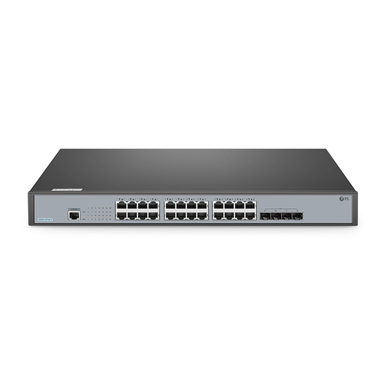
Introduction Thank you for choosing S3900 Series Stackable Managed Switches. This guide is designed to familiarize you with the layout of the switch and describes how to deploy the switch in your network. S3900-24T4S-R S3900-24F4S-R S3900-48T6S-R Accessories S3900-24T4S-R Mounting Bracket x 2 Power Cord x 2 Console Cable x 1 M4 Screw x 6... - Page 3 S3900-24F4S-R Mounting Bracket x 2 Power Cord x 2 Console Cable x 1 M4 Screw x 8 Grounding Cable x 1 Rubber Pad x 4 S3900-48T6S-R Mounting Bracket x 2 Power Cord x 2 Console Cable x 1 M4 Screw x 8 Rubber Pad x 4 Grounding Cable x 1 NOTE:...
-
Page 4: Hardware Overview
Hardware Overview Front Panel Ports S3900-24T4S-R CONSOLE RJ45 SFP+ S3900-24F4S-R CONSOLE COMBO SFP+ S3900-48T6S-R RJ45 SFP+ CONSOLE Ports Description RJ45 10/100/1000BASE-T ports for Ethernet connection SFP ports for 1G connection SFP+ SFP+ ports for 1/10G connection CONSOLE An RJ45 console port for serial management COMBO One RJ45 port and one SFP slot, with one port active at a time... -
Page 5: Front Panel Leds
Front Panel LEDS S3900-24T4S-R SYS Link/Act S3900-24F4S-R SYS Link/Act S3900-48T6S-R RJ45 SFP+ LEDs Status Description Green Switch is powered on. Green System is working properly. Blinking Green System is started normally. System is not working properly. Green Data is being transmitted or received. Link/Act no signal transmission. -
Page 6: Installation Requirements
Back Panels S3900-24T4S-R Dual Power Supplies Power Switch Grounding Point S3900-24F4S-R / S3900-48T6S-R Dual Power Supplies Power Switch Grounding Point Button Description ON means the power is switched on, while OFF means the power is cut o . Power switch Installation Requirements Only professionals are allowed to install or replace the switch. -
Page 7: Mounting The Switch
Site Environment: Do not operate it in an area that exceeds an ambient temperature of 50°C. The installation site must be well ventilated. Ensure that there is adequate air ow around the switch. Be sure that the switch is level and stable to avoid any hazardous conditions. Do not install the equipment in a dusty environment. -
Page 8: Rack Mounting
Rack Mounting O FF 1. Secure the mounting brackets to the two sides of the switch with M4 screws. 2. Attach the switch to the rack using M6 screws and cage nuts. - Page 9 Grounding the Switch O FF O FF 1. Connect one end of the grounding cable to a proper earth ground, such as the rack in which the switch is mounted. 2. Secure the grounding lug to the grounding point on the switch back panel with the washers and screws.
-
Page 10: Connecting The Power
Connecting the Power O FF 1. Plug the AC power cord into the power port on the back of the switch. 2. Connect the other end of the power cord to an AC power source. WARNING: Do not install power cable while the power is on. Connecting the RJ45 Ports 1. - Page 11 Connecting the SFP+ 1. Plug the compatible SFP+/SFP transceiver into the SFP+ port. 2. Connect a ber optic cable to the ber transceiver. Then connect the other end of the cable to another ber device. WARNING: Laser beams will cause eye damage. Do not look into bores of optical modules or optical bers without eye protection.
- Page 12 Connecting the Console Port 1. Insert the RJ45 connector into the RJ45 console port on the front of the switch. 2. Connect the DB9 female connector of the console cable to RS-232 serial port on the computer. Stacking the S3900 Series Switches S3900-24T4S-R&S3900-24F4S-R support 8 units hybrid-stacking together.
- Page 13 Configuring the Switch Con guring the Switch Using the Web-based Interface Step 1: Connect your computer to any Ethernet port of the switch using the network cable. Step 2: Set the IP address of the computer to 192.168.1.x. (“x” is any number from 2 to 254.) I nter net Proto col Versi on 4 ( TCP /I P v4) Proper tie s General Yo u c a n g e t I P s e t t i n g s a s s i g n e d a u t o m a t i c a l l y i f y o u r n e t w o r k...
- Page 14 Con guring the Switch Using the Console Port Step 1: Connect a computer to the switch's console port using the supplied console cable. Step 2: Start the terminal simulation software such as HyperTerminal on the computer. Step 3: Set the parameters of the HyperTerminal: 115200 bits per second, 8 data bits, no parity, 1 stop bit and no ow control.
-
Page 15: Product Warranty
Contact Us Product Warranty FS ensures our customers that any damage or faulty items due to our workmanship, we will o er a free return within 30 Days from the day you receive your goods. This excludes any custom made items or tailored solutions. - Page 16 Einführung Vielen Dank, dass Sie sich für die Stackable Managed Switches der S3900-Serie entschieden haben. Diese Anleitung soll Sie mit dem Layout des Switches vertraut machen und beschreibt, wie Sie den Switch in Ihrem Netzwerk einsetzen. S3900-24T4S-R S3900-24F4S-R S3900-48T6S-R Zubehör S3900-24T4S-R Montagehalterung x 2 Netzkabel x 2...
- Page 17 S3900-24F4S-R Montagehalterung x 2 Netzkabel x 2 Konsolenkabel x 1 M4-Schraube x 8 Erdungskabel x 1 Gummipad x 4 S3900-48T6S-R Montagehalterung x 2 Netzkabel x 2 Konsolenkabel x1 M4-Schraube x 8 Gummipad x 4 Erdungskabel x 1 HINWEIS: Bei den Switches der S3900-Serie werden Staubschutzkappen mitgeliefert. Bewahren Sie bitte die Staubschutzkappen ordnungsgemäß...
-
Page 18: Hardware-Übersicht
Hardware-Übersicht Ports an der Vorderseite S3900-24T4S-R CONSOLE RJ45 SFP+ S3900-24F4S-R CONSOLE COMBO SFP+ S3900-48T6S-R RJ45 SFP+ CONSOLE Ports Beschreibung RJ45 10/100/1000BASE-T Ports für Ethernet-Anschluss SFP+-Ports für 1G-Anschluss SFP+ SFP+-Ports für 1/10G-Anschluss CONSOLE RJ45 Console-Port für die serielle Verwaltung COMBO Ein RJ45-Port und ein SFP-Steckplatz, wobei jeweils ein Port aktiv ist... -
Page 19: Leds An Der Vorderseite
LEDs an der Vorderseite S3900-24T4S-R SYS Link/Act S3900-24F4S-R SYS Link/Act S3900-48T6S-R RJ45 SFP+ LEDs Status Beschreibung Grün Switch ist eingeschaltet. Grün Das System funktioniert ordnungsgemäß. Blinkend Grün Das System wird normal gestartet. Das System funktioniert nicht ordnungsgemäß. Grün Es werden Daten gesendet oder empfangen. Link/Act Keine Signalübertragung. - Page 20 Rückseite S3900-24T4S-R Duale Stromversorgung Netzschalter Erdungspunkt S3900-24F4S-R / S3900-48T6S-R Duale Stromversorgung Netzschalter Erdungspunkt Taste Beschreibung ON bedeutet, dass der Strom eingeschaltet ist, während OFF bedeutet, dass der Power switch Strom abgeschaltet ist. Installationsvoraussetzungen Die Installation oder der Austausch des Switches darf nur von Fachleuten vorgenommen werden.
-
Page 21: Montage Des Switches
Standortumgebung: Betreiben Sie das Gerät nicht in einem Bereich, in dem die Umgebungstemperatur 50°C übersteigt. Der Installationsort muss gut belüftet sein. Stellen Sie sicher, dass um den Switch herum ein ausreichender Luftstrom herrscht. Achten Sie darauf, dass der Switch eben und stabil steht, um gefährliche Bedingungen zu vermeiden. -
Page 22: Rack-Montage
Rack-Montage O FF 1. Befestigen Sie die Montagehalterungen mit M4-Schrauben an den beiden Seiten des Switches. 2. Befestigen Sie den Switch mit M6-Schrauben und Kä gmuttern am Rack. - Page 23 Erdung des Switches O FF O FF 1. Schließen Sie ein Ende des Erdungskabels an eine geeignete Erdung an, z. B. an das Rack, in dem der Switch montiert ist. 2. Befestigen Sie die Erdungslasche mit den Unterlegscheiben und Schrauben am Erdungspunkt an der Rückwand des Switches.
-
Page 24: Anschluss Der Stromversorgung
Anschluss der Stromversorgung O FF 1. Stecken Sie das Netzkabel in den Port auf der Rückseite des Switches. 2. Schließen Sie das andere Ende des Netzkabels an eine Netzstromquelle an. WARNUNG: Schließen Sie das Netzkabel nicht an, wenn das Gerät eingeschaltet ist. Anschluss der RJ45-Ports 1. - Page 25 Anschluss der SFP+-Ports 1. Stecken Sie den kompatiblen SFP+/SFP-Transceiver in den SFP+-Port. 2. Schließen Sie ein Glasfaserkabel an den Glasfasertransceiver an. Schließen Sie dann das andere Ende des Kabels an ein anderes Glasfasergerät an. WARNUNG: Laserstrahlen können zu Augenschäden führen. Schauen Sie nicht ohne Augenschutz in die Bohrungen von optischen Modulen oder Glasfasern.
- Page 26 Anschluss des Console-Ports 1. Stecken Sie den RJ45-Stecker in den RJ45 Console-Port an der Vorderseite des Switches. 2. Verbinden Sie die DB9-Buchse des Console-Kabels mit dem seriellen RS-232 Port des Computers. Stacking von Switches der S3900-Serie S3900-24T4S-R&S3900-24F4S-R unterstützen das Hybrid-Stacking von 8 Einheiten untereinander. S3900-48T6S-R unterstützt das Stacking von 6 Einheiten zwischen denselben Modellen.
-
Page 27: Kon Guration Des Switches
Kon guration des Switches Kon guration des Switches über die webbasierte Schnittstelle Schritt 1: Schließen Sie Ihren Computer über das Netzwerkkabel an einen beliebigen Ethernet Port des Switches an. Schritt 2: Stellen Sie die IP-Adresse des Computers auf 192.168.1.x ein. ("x" ist eine beliebige Zahl zwischen 2 und 254.) I nter net Proto col Versi on 4 ( TCP /I P v4) Proper tie s General... - Page 28 Kon guration des Switches über den Console-Port Schritt 1: Schließen Sie einen Computer über das mitgelieferte Konsolenkabel an den Console-Port des Switches an. Schritt 2: Starten Sie die Terminalsimulationssoftware, z. B. HyperTerminal, auf dem Computer. Schritt 3: Stellen Sie die Parameter von HyperTerminal ein: 115200 Bits pro Sekunde, 8 Datenbits, keine Parität, 1 Stoppbit und keine Flow Control.
- Page 29 2. Prüfen Sie, ob der Switch die DDM-Informationen lesen kann. 3. Prüfen Sie, ob die Geschwindigkeitseinstellung des Ports korrekt ist. 4. Versuchen Sie, das Kabel des Switches in einer Schleife zu verlegen. Support und andere Ressourcen https://www.fs.com/de/download.html Downloads Hilfecenter https://www.fs.com/de/service/fs_support.html Kontakt https://www.fs.com/de/contact_us.html...
-
Page 30: Accessoires
Introduction Merci d'avoir choisi le Switch Manageable Empilable de la Série S3900. Ce guide est conçu pour que vous puissiez vous familiariser avec la con guration du switch et décrit comment procéder à son déploiement. S3900-24T4S-R S3900-24F4S-R S3900-48T6S-R Accessoires S3900-24T4S-R Support de Montage x 2 Câble d'Alimentation x 2 Câble de Console x 1... - Page 31 S3900-24F4S-R Support de Montage x 2 Câble d'Alimentation x 2 Câble de Console x 1 Vis M4 x 8 Câble de Mise à Terre x 1 Coussins en Caoutchouc x 4 S3900-48T6S-R Câble d'Alimentation x 2 Support de Montage x 2 Câble de Console x 1 Vis M4 x 8 Coussins en Caoutchouc x 4...
-
Page 32: Aperçu Du Matériel
Aperçu du Matériel Ports du Panneau Frontal S3900-24T4S-R CONSOLE RJ45 SFP+ S3900-24F4S-R CONSOLE COMBO SFP+ S3900-48T6S-R RJ45 SFP+ CONSOLE Ports Description RJ45 Ports 10/100/1000BASE-T pour une connexion Ethernet Ports SFP pour une connexion 1G SFP+ Ports SFP+ pour une connexion 1/10G CONSOLE Un port console RJ45 pour la gestion en série COMBO... -
Page 33: Indicateurs Led Du Panneau Frontal
Indicateurs LED du Panneau Frontal S3900-24T4S-R SYS Link/Act S3900-24F4S-R SYS Link/Act S3900-48T6S-R RJ45 SFP+ LEDs Statut Description Vert Le switch est sous tension. Vert Le système fonctionne correctement. Vert Clignotant Le système a démarré normalement. Éteint Le système ne fonctionne pas correctement. Vert Des données sont transmises ou reçues. -
Page 34: Panneau Arrière
Panneau Arrière S3900-24T4S-R Alimentations Doubles Interrupteur de Mise sous Tension Point de Mise à Terre S3900-24F4S-R / S3900-48T6S-R Alimentations Doubles Interrupteur de Mise sous Tension Point de Mise à Terre Button Description ON indique que le système est mis sous tension, Interrupteur de mise sous tension OFF indique que le système est arrêté. -
Page 35: Site De L'installation
Site de l'Installation : Ne pas installer l'appareil dans un endroit où la température ambiante dépasse 50°C. Le site d'installation doit être bien ventilé. Assurez-vous que la circulation d'air autour du switch soit su sante. Assurez-vous que le switch est à niveau et stable pour éviter tout risque. Ne pas installer l'équipement dans un environnement poussiéreux. -
Page 36: Montage Sur Rack
Montage sur Rack O FF 1. Fixez les supports de montage aux deux côtés du switch avec des vis M4. 2. Fixez le switch au rack à l'aide de vis M6 et d'écrous à cage. - Page 37 Mise à Terre du Switch O FF O FF 1. Connectez une extrémité du câble de mise à terre à une terre appropriée, telle que le rack sur lequel le switch est monté. 2. Fixez la che de mise à terre au point de mise à terre sur le panneau arrière du switch à l'aide des rondelles et des vis.
-
Page 38: Connexion De L'alimentation
Connexion de l'Alimentation O FF 1. Branchez le câble d'alimentation CA dans le port d'alimentation situé à l'arrière du switch. 2. Connectez l'autre extrémité du câble d'alimentation à une source de courant alternatif. AVERTISSEMENT: Ne pas installer le câble d'alimentation lorsque l'appareil est mis sous tension. -
Page 39: Connexion Du Sfp
Connexion du SFP+ 1.Branchez le module SFP+/SFP compatible sur le port SFP+. 2.Connectez un câble de bre optique au module optique. Puis connectez l'autre extrémité du câble à un autre appareil à bre. AVERTISSEMENT: Les faisceaux laser peuvent causer des lésions oculaires. Ne regardez pas dans les alésages des modules ou des bres optiques sans protection oculaire. -
Page 40: Connexion Du Port Console
Connexion du Port Console 1. Insérez le connecteur RJ45 dans le port de console RJ45 situé à l'avant du switch. 2. Connectez le connecteur femelle DB9 du câble de la console au port série RS-232 de l'ordinateur. Empilage des Switchs de la Série S3900 Les modèles S3900-24T4S-R et S3900-24F4S-R prennent en charge l'empilement hybride de 8 unités. - Page 41 Con guration du Switch Con guration du Switch à l'Aide de l'Interface Web Étape 1 : Connectez votre ordinateur à n'importe quel port Ethernet du switch à l'aide du câble réseau. Étape 2 : Dé nissez l'adresse IP de l'ordinateur sur 192.168.1.x. ("x" est un nombre quelconque compris entre 2 et 254).
-
Page 42: Dépannage
Con guration du Switch à l'Aide du Port Console Étape 1 : Connectez un ordinateur au port de console du switch à l'aide du câble de console fourni. Étape 2 : Démarrez le logiciel HyperTerminal sur l'ordinateur. Étape 3 : Réglez les paramètres de l'HyperTerminal : 115200 bits par seconde, 8 bits de données, pas de parité, 1 bit d'arrêt et pas de contrôle de ux. -
Page 43: Support Et Autres Informations
Garantie des Produits FS garantit à ses clients que tout dommage ou article défectueux dû à sa fabrication peut être retourné dans un délai de 30 jours à compter de la date de réception de la marchandise. Cela exclut tout article fabriqué... -
Page 44: Compliance Information
Any changes or modi cations not expressly approved by the grantee of this device could void the user's authority to operate the equipment. Responsible party (only for FCC matter) FS.COM Inc. 380 Centerpoint Blvd, New Castle, DE 19720, United States https://www.fs.com... - Page 45 Die FS.COM GmbH erklärt hiermit, dass dieses Gerät mit der Richtlinie 2014/30/EU und 2014/35/EU konform ist. Eine Kopie der EU-Konformitätserklärung nden Sie unter www.fs.com/de/company/quality_control.html. FS.COM GmbH déclare par la présente que cet appareil est conforme à la Directive 2014/30/UE et 2014/35/UE. Une copie de la Déclaration UE de Conformité est disponible sur https://www.fs.com/fr/company/quality_control.html FS.COM LIMITED...