
Manuels Connexes pour FS S5850 Serie


Sommaire des Matières pour FS S5850 Serie
- Page 1 MANAGED L3 DATA CENTER SWITCHES MANAGED L3-SWITCHES FÜR RECHENZENTREN SWITCHS MANAGEABLES L3 POUR CENTRES DE DONNÉES Quick Start Guide V1.0 Quick Start Anleitung Guide de Démarrage Rapide...
- Page 2 Introduction Thank you for choosing S5850 Series switches. This guide is designed to familiarize you with the layout of the switches and describes how to deploy the switches in your network. S5850-48S8C S5850-48B8C S5850-48S8C-DC Accessories Power Cord x2 Cat 5e Cable x1 Console Cable (DB9 to RJ45)x1 Rubber Pad x4 Grounding Cable x1...
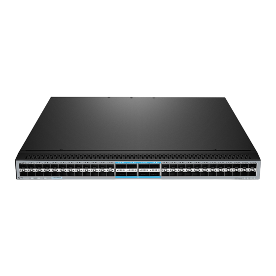
- Page 3 Hardware Overview Front Panel Ports SS5850-48S8C-DC 100G QSFP28 25G SFP28 Ports Description SFP28 SFP28 ports for 1/10G transceivers QSFP28 QSFP28 ports for 40/100G transceivers Front Panel LEDs S5850-48S8C-DC 100G QSFP28 Breakout 25G SFP28 LEDs State Description ID indication function enable. Blue ID indication function disable.
- Page 4 LEDs State Description 25G port is linked. Green Blinking 25G packets are receiving or transmitting. SFP28 10G/1G port is linked. Amber Blinking 10G/1G packets are receiving or transmitting. Port is not linked 100G/40G port is linked. Green Blinking 100G/40G packets are receiving or transmitting. QSFP28 10G/1G port is linked.
- Page 5 Ports Description A power supply module port Power Supply Module RJ45 Console Port (CON) An RJ45 console port for serial management An Ethernet management port A USB management port Back Panel LEDs LEDs State Description ID indication function enable. Blue ID indication function disable.
- Page 6 Anti-static gloves must be worn when replacing interface board to prevent static electricity from damaging veneer. Installation Site To ensure a normal work environment, S5850 series switches should have the following requirements for workplace: Ensure that there are some spaces at the inlet and outlet of switch for heat dissipation of switch chassis.
- Page 7 2. Fix the rear mounting brackets to the rack. 3. Push the switch slightly into the rack along the sliding rails, and x the other end of front mounting brackets upon the front hold strip of rack using screws and matching nuts.
- Page 8 Grounding the Switch 1. Connect one end of the grounding cable to a proper earth ground, such as the rack in which the switch is mounted. 2. Secure the grounding lug to the grounding point on the switch back panel with the washer and screws.
- Page 9 Connecting the Power 1. Plug the AC power cord into the power port on the back of the switch. 2. Connect the other end of the power cord to a power source. (The S5850-48S8C-DC power port is di erent from the power ports of S5850-48S8C and S5850-48B8C.
- Page 10 Connecting the QSFP28 Ports 1. Plug the compatible QSFP28 transceiver into the QSFP28 port. 2. Connect a ber optic cable to the ber transceivers. Then connect the other end of the cable to other ber devices. Connecting the USB port 1.
- Page 11 Connecting the Console Port 1. Insert the RJ45 connector of the console cable into the RJ45 console port on the back of the switch. 2. Connect the other end of the console cable to the RS-232 serial port on the computer. Connecting the ETH Port 1.
- Page 12 Configuring the Switch Configuring the Switch Using the Web-based Interface Step 1: Connect the computer to the Management port of the switch using the network cable. Step 2: Set the IP address of the computer to 192.168.1.x. ("x" is any number from 2 to 254.). Set the subnet mask of the computer to 255.255.255.0 I nter ne t Pro to co l Ve rs i on 4 ( TC P/ I P v4) Pro pe r ti es General...
- Page 13 Configuring the Switch Using the Console Port Step 1: Connect a computer to the switch's console port using the supplied console cable. Step 2: start simulation software such as HyperTerminal on the computer. Step 3: Set the parameters of the HyperTerminal: 115200 bits per second, 8 data bits, no parity, 1 stop bit and no flow control.
- Page 14 Troubleshooting Loading Failure Troubleshooting After loading fails, the system will keep running in the original version. At this time, users should re-check if physical port connection are good rstly. If some ports are not connected, then re-connect them to ensure that physical connections are correct, and begin re-loading. If physical connections are correct, then check the loading process information displayed on the super terminal to verify if there are input errors.
- Page 15 Contact Us Product Warranty FS ensures our customers that any damage or faulty items due to our workmanship, we will o er a free return within 30 days from the day you receive your goods. This excludes any custom made items or tailored solutions.
- Page 16 Einführung Vielen Dank, dass Sie sich für Switches der Serie S5850 entschieden haben. Diese Anleitung soll Sie mit dem Layout der Switches vertraut machen und beschreibt, wie Sie die Switches in Ihrem Netzwerk einsetzen. S5850-48S8C S5850-48B8C S5850-48S8C-DC Zubehör Netzkabel x2 Konsolenkabel (DB9 auf RJ45) x1 Cat 5e-Kabel x1 Erdungskabel x1...
- Page 17 Hardware-Übersicht Ports an der Vorderseite S5850-48S8C-DC 100G QSFP28 25G SFP28 Port Beschreibung SFP28 SFP28 für 1/10G Transceiver QSFP28 QSFP28 Ports für 40/100G Transceiver LEDs an der Vorderseite S5850-48S8C-DC 100G QSFP28 Breakout 25G SFP28 Status Beschreibung ID-Anzeigefunktion aktivieren. Blau ID-Anzeigefunktion deaktivieren. Grün Das System läuft normal.
- Page 18 Status Beschreibung 25G-Port ist verbunden. Grün Blinkt 25G-Pakete werden empfangen oder gesendet. SFP28 10G/1G-Port ist verbunden. Braun Blinkt 10G/1G-Pakete werden empfangen oder gesendet. Der Port ist nicht verbunden. Der 100G/40G-Anschluss ist verbunden. Grün Blinkt 100G/40G-Pakete werden empfangen oder gesendet. QSFP28 Der 10G/1G-Port ist verbunden.
- Page 19 Port Beschreibung Ein Stromversorgungsmodulport Stromversorgung RJ45 Console-Port (CON) Ein RJ45-Console-Port für die serielle Verwaltung Ein Ethernet-Verwaltungsport Ein USB-Verwaltungsport LEDs an der Rückseite Status Beschreibung ID-Anzeigefunktion aktivieren. Blau ID-Anzeigefunktion deaktivieren. Das System läuft normal. Grün Braun Im System ist ein Alarm oder Fehler aufgetreten. Kein Strom oder das System läuft nicht oder es liegt eine Fehlfunktion vor.
- Page 20 Beim Austausch der Schnittstellenkarte müssen antistatische Handschuhe getragen werden, um zu verhindern, dass statische Elektrizität das Gehäuse beschädigt. Installationsort Um eine normale Arbeitsumgebung zu gewährleisten, sollten die Switches der Serie S5850 die folgenden Anforderungen an den Arbeitsplatz erfüllen: Stellen Sie sicher, dass am Ein- und Ausgang des Switches genügend Platz für dieWärmeableitung des Switch-Gehäuses vorhanden ist.
- Page 21 2. Befestigen Sie die hinteren Montagehalterungen am Rack. 3. Schieben Sie den Switch entlang der Gleitschienen leicht in das Rack hinein, und befestigen Sie das andere Ende der vorderen Montagehalterungen mit einer Schraube und der dazugehörigen Mutter an der vorderen Halteleiste des Racks.
- Page 22 Erdung des Switches 1. Schließen Sie ein Ende des Erdungskabels an eine geeignete Erdung an, z. B. an das Rack, in dem der Switch montiert ist. 2. Befestigen Sie die Erdungslasche mit den Unterlegscheiben und Schrauben am Erdungspunkt an der Rückwand des Switches. HINWEIS: 1.
- Page 23 Anschließen der Stromversorgung 1. Stecken Sie das Netzkabel in den Netzanschluss auf der Rückseite des Switches. 2. Schließen Sie das andere Ende des Netzkabels an eine Stromquelle an. (Der Netzanschluss des S5850-48S8C-DC unterscheidet sich von den Netzanschlüssen des S5850-48S8Cund des S5850-48B8C.) WARNUNG: Installieren Sie das Netzkabel nicht, während das Gerät eingeschaltet ist.
- Page 24 Anschließen der QSFP28-Ports 1. Stecken Sie den kompatiblen QSFP28-Transceiver in den QSFP28-Port. 2. Verbinden Sie ein Glasfaserkabel mit den Glasfaser-Transceivern. Verbinden Sie dann das andere Ende des Kabels mit anderen Glasfasergeräten. Anschließen des USB-Ports 1. Verbinden Sie die DB9-Buchse des Mini-USB-Steckers mit dem seriellen RS-232-Port des Computers.
- Page 25 Anschließen des Console-Ports 1. Stecken Sie den RJ45-Stecker des Console-Kabels in den RJ45-Console-Port auf der Rückseite des Switches. 2. Schließen Sie das andere Ende des Console-Kabels an den seriellen RS-232-Port des Computers an. Anschließen des ETH-Ports 1. Schließen Sie ein Ende eines Standard-RJ45-Ethernet-Kabels an den Ethernet-Port eines Computers an.
- Page 26 Kon gurieren des Switches Kon gurieren des Switches über die webbasierte Schnittstelle Schritt 1: Schließen Sie den Computer über das Netzwerkkabel an den Verwaltungsport des Switches an. Schritt 2: Stellen Sie die IP-Adresse des Computers auf 192.168.1.x ein ("x" ist eine beliebige Zahlvon 2 bis 254.).
- Page 27 Kon gurieren des Switches über den Console-Port Schritt 1: Schließen Sie einen Computer über das mitgelieferte Console-Kabel an den Console-Portdes Switches an. Schritt 2: Starten Sie eine Simulationssoftware wie z. B. HyperTerminal auf dem Computer. Schritt 3: Stellen Sie die Parameter von HyperTerminal ein: 115200 Bits pro Sekunde, 8 Datenbits, keine Parität, 1 Stoppbit und keine Flusskontrolle.
- Page 28 Fehlersuche Fehlerbehebung bei Ladefehlern Wenn das Laden fehlschlägt, läuft das System in der ursprünglichen Version weiter. Zu diesem Zeitpunkt sollten die Benutzer zunächst überprüfen, ob die physischen Portverbindungen in Ordnung sind. Wenn einige Ports nicht angeschlossen sind, schließen Sie sie erneut an, um sicherzustellen, dass die physikalischen Verbindungen korrekt sind, und beginnen Sie mit dem erneuten Laden.
- Page 29 Produktgarantie FS garantiert seinen Kunden, dass wir bei Schäden oder fehlerhaften Artikeln, die auf unsere Verarbeitung zurückzuführen sind, eine kostenlose Rückgabe innerhalb von 30 Tagen nach Erhalt der Ware anbieten. Dies gilt nicht für maßgefertigte Artikel oder maßgeschneiderte Lösungen.
- Page 30 Introduction Merci d'avoir choisi les switchs de la Série S5850. Ce guide est conçu pour vous familiariser avec la con guration du switch et vous indique comment procéder à son déploiement. S5850-48S8C S5850-48B8C S5850-48S8C-DC Accessoires Câble d’alimentation x2 Câble de console (DB9 à RJ45) x1 Câble Cat5e x1 Câble de mise à...
- Page 31 Aperçu du Matériel Ports du Panneau Frontal S5850-48S8C-DC 100G QSFP28 25G SFP28 Ports Description SFP28 SFP28 pour modules 1/10G QSFP28 QSFP28 pour modules 40/100G Indicateurs LED du Panneau Frontal S5850-48S8C-DC 100G QSFP28 Breakout 25G SFP28 Statut Description Allumé Fonction d'indication de l'ID activée. Bleu Éteint Fonction d'indication de l'ID désactivée.
- Page 32 Description Statut Allumé Le port 25G est relié. Vert Clignotant Des paquets 25G sont reçus ou transmis. SFP28 Allumé Le port 1G/10G est relié. Jaune Clignotant Des paquets 1G/10G sont reçus ou transmis. Le port n’est pas relié. Éteint Allumé Le port 40G/100G est relié.
- Page 33 Port Description Emplacement pour le module d'alimentation Module d'Alimentation Électrique Port RJ45 Console (CON) Port console RJ45 pour la gestion en série Port de gestion Ethernet Port de gestion USB Indicateurs LED du Panneau Arrière Statut Description Allumé Fonction d'indication de l'ID activée. Bleu Éteint Fonction d'indication de l'ID désactivée.
- Page 34 Site de l’Installation Pour garantir un environnement de travail normal, il est recommandé de respecter les exigences suivantes pour l’installation rdes switchs de la série S5850 : Assurez-vous qu'il y a des espaces libres autour du switch pour la dissipation de la chaleur du châssis du switch.
- Page 35 2. Fixez les supports de montage arrière au rack. 3. Poussez délicatement le switch dans le rack le long des rails coulissants, et xez l'autre extrémité des supports de montage frontaux sur la barre de maintien frontale du rack à l'aide de vis et des écrous correspondants.
- Page 36 Mise à la Terre du Switch 1. Connectez une extrémité du câble de mise à la terre à une terre appropriée, telle que le rack dans lequel le switch est installé. 2. Fixez la prise de mise à la terre au point de mise à la terre sur le panneau arrière du switch à l'aide des rondelles et des vis.
- Page 37 Connexion de l'Alimentation 1. Branchez le câble d'alimentation dans le port d'alimentation situé sur le panneau arrière du switch. 2. Connectez l'autre extrémité du câble d'alimentation à une source de courant alternatif. (Le port d'alimentation du S5850-48S8C-DC est di érent des ports d'alimentation du S5850-48S8C et du S5850-48B8C.) AVERTISSEMENT : Ne pas brancher le câble d'alimentation lorsque l'appareil est sous...
- Page 38 Connexion des Ports QSFP28 1. Branchez le module QSFP28 compatible au port QSFP28. 2. Connectez un câble en bre optique au module optique. Puis l'autre extrémité du câble à un autres dispositifs à bre. Connexion du Port USB 1. Connectez le connecteur femelle DB9 du mini USB au port série RS-232 de l'ordinateur. 2.
- Page 39 Connexion du Port Console 1. Insérez le connecteur RJ45 du câble de console dans le port de console RJ45 situé à l'arrière du switch. 2. Connectez l'autre extrémité du câble de la console au port série RS-232 de l'ordinateur. Connexion du Port ETH 1.
- Page 40 Con guration du Switch Con guration du Switch via l'Interface Web Étape 1 : Connectez l'ordinateur au port du switch à l'aide du câble réseau. Étape 2 : Dé nissez l'adresse IP de l'ordinateur sur 192.168.1.x ("x" est un nombre compris entre 2 et 254).
- Page 41 Con guration du Switch en Utilisant le Port Console Étape 1 : Connectez un ordinateur au port de console du switch à l'aide du câble de console. Étape 2 : Démarrez le logiciel HyperTerminal sur l'ordinateur. Étape 3 : Réglez les paramètres de l'HyperTerminal : 115200 bits par seconde, 8 bits de données, pas de parité, 1 bit d'arrêt et pas de contrôle de ux.
- Page 42 Dépannage Dépannage en Cas d'Échec du Chargement Après l'échec du chargement, le système continuera à fonctionner dans sa version originale. À ce moment-là, les utilisateurs doivent d'abord véri er si la connexion du port physique est bien établie. Si certains ports ne sont pas connectés correctement, reconnectez-les et veuillez vous assurer que les connexions physiques sont conformes, puis recommencez le chargement.
- Page 43 Garantie du Produit FS garantit à ses clients que tout article endommagé ou défectueux dû à sa fabrication pourra être retourné gratuitement dans un délai de 30 jours à compter de la date de réception de la marchandise. Cela exclut tout article ou solution sur mesure ou les solutions personnalisées.
- Page 44 Die FS.COM GmbH erklärt hiermit, dass dieses Gerät mit der Richtlinie 2014/30/EU und 2014/35/EU konform ist. Eine Kopie der EU-Konformitätserklärung fnden Sie unter www.fs.com/de/company/quality_control.html FS.COM GmbH déclare par la présente que cet appareil est conforme à la Directive 2014/30/UE et 2014/35/UE. Une copie de la Déclaration UE de Conformité est disponible sur https://www.fs.com/fr/company/quality_control.html FS.COM LIMITED...
- Page 45 UKCA Hereby, FS.COM Innovation Ltd declares that this device is in compliance with the Directive SI 2016 No.1091 and SI 2016 No. 1101 English: This device contains licence-exempt transmitter(s)/receiver(s) that comply with Innovation, Science and Economic Development Canada’s licence-exempt RSS(s). Operation is subject to the following two conditions: (1) This device may not cause interference.
- Page 46 Q.C. PASSED Copyright © 2022 FS.COM All Rights Reserved.