Table des Matières
Publicité
Les langues disponibles
Les langues disponibles
Liens rapides
S 8 0 5 0
-2 0 Q 4
C
1
3
1
2
4
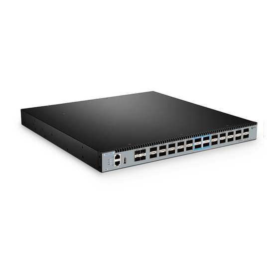
S8050-20Q4C
L3 FULLY MANAGED PLUS SPINE SWITCH
L3 FULLY MANAGED PLUS SPINE-SWITCH
SWITCH SPINE L3+ ENTIÈREMENT GÉRÉ
Quick Start Guide
Quick-Start Anleitung
Guide de Démarrage Rapide
2
3
4
5
6
7
8
9
10
11
V2.1
12
13
10
15
16
17
18
19
20
21
40 G/ 10
0G
22
23
24
40 GE Bre
ak ou t
1
2
3
4
Publicité
Table des Matières

Manuels Connexes pour FS S8050-20Q4C


Sommaire des Matières pour FS S8050-20Q4C
- Page 1 S 8 0 5 0 -2 0 Q 4 40 G/ 10 40 GE Bre ak ou t S8050-20Q4C L3 FULLY MANAGED PLUS SPINE SWITCH L3 FULLY MANAGED PLUS SPINE-SWITCH SWITCH SPINE L3+ ENTIÈREMENT GÉRÉ Quick Start Guide V2.1 Quick-Start Anleitung...
-
Page 2: Accessories
Introduction Thank you for choosing S8050-20Q4C spine switch. This guide is designed to familiarize you with the layout of the switch and describes how to deploy the switch in your network. S8050-20Q4C 40G/100G 40GE Breakout S8050-20Q4C Accessories Power Cord x 2... -
Page 3: Hardware Overview
Hardware Overview Front Panel Ports Console SFP+ QSFP+ QSFP28 QSFP+ S8 05 0- 2 0 Q4 C 40G/100G 40GE Breakout Ports Description SFP+ SFP+ ports for 1 0G connection QSFP+ QSFP+ ports for 40G connection QSFP28 QSFP28 ports for 1 00G connection An Ethernet management port Console An RJ45 console port for serial management... - Page 4 LEDS Status Description Green System is abnormal. Blinking Green Quickly (2Hz) System is running in u-boot mode. Blinking Green Slowly (0.5Hz) System is normally running. Amber System occurs alarm or error. Blinking Amber Quickly (2Hz) System is initial in u-boot mode. Blinking Amber Slowly (0.5Hz) System software is in initial state.
-
Page 5: Back Panel
Back Panel Grounding Point 4 Hot-swappable Fans 2 Hot-swappable Power Supplies Installation Requirements Before you begin the installation, make sure that you have the following: Phillips screwdriver. Standard-sized, 19" wide rack with a minimum of 1U height available. Category 5e or higher RJ-45 Ethernet cables for connecting the network devices. Site Environment: Do not operate it in an area that exceeds an ambient temperature of 45 °C . -
Page 6: Mounting The Switch
Mounting the Switch S 8 0 5 0 - 2 0 Q 4 C Desk Mounting S8050 -20Q4 C 40G/100G 40GE Breakout 1. Attach four rubber pads to the bottom. 2. Place the chassis on a desk. Rack Mounting 40 G /1 00 40 GE Br ea ko ut 1. - Page 7 4 0 G /1 0 0 G 40 G E Br ea ko ut 2. Attach the switch to the rack using four M6 screws and cage nuts. Grounding the Switch 1 . Connect one end of the grounding cable to a proper earth ground, such as the rack in which the switch is mounted.
-
Page 8: Connecting The Power
Connecting the Power 1. Plug the AC power cord into the power port on the back of the switch. 2. Connect the other end of the power cord to an AC power source. WARNING: Do not install power cable while the power is on. Connecting the SFP+ Ports S 8 0 5 0 - 2 0 Q 4 C... - Page 9 Connecting the QSFP+ Ports S8 0 5 0 - 2 0 Q 4 C 40 G/ 10 0G 40 GE Bre ak ou t connect DAC cables to the QSFP+ slots. Connecting the QSFP28 Ports S 8 0 5 0 - 2 0 Q 4 C 40 G/ 10 0G 40 GE Bre...
- Page 10 Connecting the USB Port S 8 0 5 0 -2 0 Q 4 C 40 G/ 10 0G 40 GE B Connecting the Console Port S 8 0 5 0 -2 0 Q 4 1. Insert the RJ45 connector of the console cable into the RJ45 console port on the front of the switch. 2.
- Page 11 Connecting the ETH Port S 8 0 5 0 - 2 0 Q 4 C 40 G/ 10 0G Bre ak ou t 1. Connect one end of a standard RJ45 Ethernet cable to a computer. 2. Connect the other end of the cable to the ETH port on the front of the switch. 40 G /1 00 40 G E Br ea ko ut...
- Page 12 Step 1: Connect the computer to the Management port of the switch using the network cable. Step 2: Set the IP address of the computer to 192.168.1.x ("x" is any number from 2 to 254.). Set the subnet mask of the computer to 255.255.255.0 40 GE Bre ak ou t Step 3: Open a browser, type http://192.168.1.1, and enter the default username and password,...
- Page 13 Step 1 : Connect a computer to the switch's console port using the supplied console cable. Step 2: Start the terminal simulation software such as HyperTerminal on the computer. Step 3: Set the parameters of the HyperTerminal: 1 1 5200 bits per second, 8 data bits, no parity, 1 stop Step 4: Enter the default username and password, admin/admin.
- Page 14 Troubleshooting Loading Failure Troubleshooting After loading fails, the system will keep running in the original version. At this time, users should them to ensure that physical connections are correct, and begin re-loading. If physical connections are correct, then check the loading process information displayed on the super terminal to verify if there are input errors.
-
Page 15: Product Warranty
30 Days from the day you receive your goods. This excludes any custom made items or tailored solutions. Warranty: S8050-20Q4C Switch enjoys 5 years limited warranty against defect in materials or workmanship. For more details about warranty, please check at https://www.fs.com/policies/warranty.html... - Page 16 Einführung Vielen Dank, dass Sie sich für den S8050-20Q4C Spine-Switch entschieden haben. Diese Anleitung soll Sie mit dem Layout des Switches vertraut machen und beschreibt, wie Sie den Switch in Ihrem Netzwerk einsetzen. S8050-20Q4C 40G/100G 40GE Breakout S8050-20Q4C Zubehör Netzkabel x 2...
-
Page 17: Hardware-Übersicht
Hardware-Übersicht Ports an der Vorderseite Console SFP+ QSFP+ QSFP28 QSFP+ S 805 0 -2 0 Q4 C 40G/100G 40GE Breakout Ports Beschreibung SFP+ SFP+-Ports für 10G-Verbindungen QSFP+ QSFP+-Ports für 40G-Verbindungen QSFP28 QSFP28-Ports für 100G-Verbindungen Ethernet-Verwaltungsanschluss Console RJ45-Konsolenanschluss für die serielle Verwaltung USB-Verwaltungsanschluss für Software- und LEDs an der Vorderseite SFP+... - Page 18 LEDS Status Beschreibung Grün Das System arbeitet abnormal. Schnell Blinkend Grün (2Hz) Das System läuft im U-Boot-Modus. Langsam Blinkend Grün (0,5Hz) Das System läuft normal. Braun Das System meldet einen Alarm oder Fehler. Schnell Blinkend Braun (2Hz) System initialisiert im U-Boot-Modus. Langsam Blinkend Braun (0,5Hz) Initialisierungszustand.
- Page 19 Rückseite Erdungspunkt 4 Hot-Swap-fähige Lüfter 2 Hot-Swap-fähige Netzteile Installationsvoraussetzungen Bevor Sie mit der Installation beginnen, vergewissern Sie sich, dass Sie Folgendes zur Hand haben: Kreuzschlitzschraubendreher. Ein 19"-Rack in Standardgröße mit einer Mindesthöhe von 1 HE. RJ-45-Ethernet-Kabel der Kategorie 5e oder höher für den Anschluss der Netzwerkgeräte. Standortumgebung: Betreiben Sie das Gerät nicht in einem Bereich, in dem die Umgebungstemperatur 45°C überschreitet.
-
Page 20: Montage Des Switches
Montage des Switches S 8 0 5 0 - 2 0 Q 4 C Montage auf einem Tisch S8050 -20Q4 C 40G/100G 40GE Breakout 1. Bringen Sie vier Gummipads an der Unterseite an. 2. Stellen Sie das Gehäuse auf einen Tisch. Rack-Montage 40 G /1 00 40 GE Br... - Page 21 4 0 G /1 0 0 G 40 G E Br ea ko ut Erdung des Switches 1. Schließen Sie ein Ende des Erdungskabels an eine geeignete Erdung an, z. B. an das Rack, in dem der Switch montiert ist. 2.
-
Page 22: Anschließen Der Stromversorgung
Anschließen der Stromversorgung 1. Stecken Sie das Netzkabel in den Netzanschluss auf der Rückseite des Switches. 2. Schließen Sie das andere Ende des Netzkabels an eine Netzstromquelle an. WARNUNG: Schließen Sie das Netzkabel nicht an, wenn das Gerät eingeschaltet ist. Anschließen der SFP+-Ports S 8 0 5 0 - 2 0 Q 4 C... - Page 23 Anschließen der QSFP+ Ports S8 0 5 0 - 2 0 Q 4 C 40 G/ 10 0G 40 GE Bre ak ou t Installieren Sie zunächst QSFP+-Transceiver und schließen Sie dann Glasfaserkabel an die T ransceiver-Ports an, oder schließen Sie DAC-Kabel an die QSFP+-Steckplätze an. Anschließen der QSFP28-Ports S 8 0 5 0 - 2 0 Q 4 C...
-
Page 24: Anschließen Des Usb-Ports
Anschließen des USB-Ports S 8 0 5 0 - 2 0 Q 4 C 40 G/ 10 0G 40 GE B Stecken Sie die Universal Serial Bus (USB) Ascheplatte in den USB-Port für Software- und Anschließen des Konsolenports S 8 0 5 0 -2 0 Q 4 1. -
Page 25: Anschließen Des Eth-Ports
Anschließen des ETH-Ports S 8 0 5 0 -2 0 Q 4 C 40 G/ 10 0G Bre ak ou t 1. Schließen Sie ein Ende eines standardmäßigen RJ45-Ethernet-Kabels an einen Computer an. 2. Schließen Sie das andere Ende des Kabels an den ETH-Port an der Vorderseite des Switches an. 40 G /1 00 40 G E Br ea ko ut... - Page 26 Schritt 1: Schließen Sie den Computer mit dem Netzwerkkabel an den Verwaltungsanschluss des Switches an. Schritt 2: Stellen Sie die IP-Adresse des Computers auf 192.168.1.x ein ("x" ist eine beliebige Zahl von 2 bis 254.). Setzen Sie die Subnetzmaske des Computers auf 255.255.255.0 40 GE Bre ak ou t http://192.168.1.1 ein, und geben Sie den...
- Page 27 Schritt 1: Schließen Sie einen Computer über das mitgelieferte Konsolenkabel an den Konsolenanschluss des Switches an. Schritt 2: Starten Sie die Terminalsimulationssoftware wie HyperTerminal auf dem Computer. Schritt 3: Stellen Sie die Parameter von HyperTerminal ein: 1 1 5200 Bits pro Sekunde, 8 Datenbits, keine Parität, 1 Stoppbit und keine Flusskontrolle.
-
Page 28: Fehlerbehebung Bei Ladefehlern
Fehlerbehebung Fehlerbehebung bei Ladefehlern Wenn das Laden fehlschlägt, läuft das System in der ursprünglichen Version weiter. Zu diesem Z eitpunkt sollten die Benutzer zunächst überprüfen, ob die physischen Port-Verbindungen in Ordnung sind. Wenn einige Ports nicht angeschlossen sind, schließen Sie sie erneut an, um sicherzustellen, dass die physikalischen Verbindungen korrekt sind, und beginnen Sie mit dem erneuten Laden. - Page 29 Produktgarantie FS versichert den Kunden, dass wir bei Schäden oder fehlerhaften Artikeln, die auf unsere Verarbeit- ung zurückzuführen sind, eine kostenlose Rückgabe innerhalb von 30 Tagen ab dem Tag des Erhalts der Ware anbieten. Dies gilt nicht für Sonderanfertigungen oder maßgeschneiderte Lösungen.
-
Page 30: Accessoires
Introduction Nous vous remercions d'avoir choisi le switch spine S8050-20Q4C. Ce guide est conçu pour que vous déploiement. S8050-20Q4C 40G/100G 40GE Breakout S8050-20Q4C Accessoires Câble d'Alimentation x 2 Câble de Console x 1 Câble CatSe x 1 Câble de Mise à Terre x 1... -
Page 31: Aperçu Du Matériel
Aperçu du Matériel Ports du Panneau Frontal Console SFP+ QSFP+ QSFP28 QSFP+ S 80 50 - 20 Q4 C 40G/100G 40GE Breakout Ports Description SFP+ Ports SFP+ pour la connexion 10G QSFP+ Ports QSFP+ pour la connexion 40G QSFP28 Ports QSFP28 pour la connexion 100G Port de gestion Ethernet Console Port console RJ45 pour la gestion en série... - Page 32 Statut Description Vert Le système présente une anomalie. Vert Clignotant Rapidement (2Hz) Le système fonctionne en mode u-boot. Vert Clignotant Lentement (0.5Hz) Le système fonctionne normalement. Le système déclenche une alarme ou Jaune présente une erreur. Jaune Clignotant Rapidement (2Hz) Le système est lancé...
-
Page 33: Panneau Arrière
Panneau Arrière Point de Mise à Terre 4 Ventilateurs Remplaçables à Chaud 2 Alimentations Électriques Remplaçables à Chaud Exigences d'Installation Avant de commencer l'installation, assurez-vous que vous disposez des éléments suivants : Tournevis phillips. Rack de taille standard, 19" de large, avec une hauteur minimum de 1U disponible. Des câbles Ethernet RJ-45 de catégorie 5e ou supérieure pour la connexion des périphériques réseau. -
Page 34: Installation Du Switch
Installation du Switch S 8 0 5 0 - 2 0 Q 4 C Installation sur Support S8050 -20Q4C 40G/100G 40GE Breakout 1. Fixez quatre coussins en caoutchouc à la base. 2. Placez le châssis sur le support. Installation sur Rack 40 G /1 00 40 GE Br ea ko ut... -
Page 35: Mise À Terre Du Switch
4 0 G /1 0 0 G 40 G E Br ea ko ut 2. Fixez le switch au rack à l'aide de quatre vis M6 et d'écrous à cage. Mise à Terre du Switch 1. Connectez une extrémité du câble de mise à terre à une terre appropriée, telle que le rack sur lequel le switch est monté. -
Page 36: Connexion De L'alimentation Électrique
Connexion de l'Alimentation Électrique 1. Branchez le câble d'alimentation CA dans le port d'alimentation situé à l'arrière du switch. 2. Connectez l'autre extrémité du câble d'alimentation à une source de courant alternatif. ATTENTION: Ne pas installer le câble d'alimentation lorsque l'appareil est sous tension. Connexion aux Ports SFP+ S 8 0 5 0 - 2 0 Q 4 C... -
Page 37: Connexion Aux Ports Qsfp
Connexion aux Ports QSFP+ S8 0 5 0 -2 0 Q 4 C 40 G/ 10 0G 40 GE Bre ak ou t ports des émetteurs-récepteurs, ou connectez les câbles DAC aux emplacements QSFP+. Connexion aux Ports QSFP28 S8 0 5 0 -2 0 Q 4 C 40 G/ 10 0G 40 GE Bre... -
Page 38: Connexion Au Port Usb
Connexion au Port USB S8 0 5 0 -2 0 Q 4 C 40 G/ 10 0G 40 GE B mise à jour du logiciel. Connexion au Port Console S 8 0 5 0 -2 0 Q 4 1. Insérez le connecteur RJ45 du câble de la console dans le port de console RJ45 situé à l'avant du switch. -
Page 39: Connexion Au Port Eth
Connexion au Port ETH S8 0 5 0 -2 0 Q 4 C 40 G/ 10 0G Bre ak ou t 1. Connectez une extrémité d'un câble Ethernet standard RJ45 à un ordinateur. 2. Connectez l'autre extrémité du câble au port ETH situé à l'avant du switch. 40 G /1 00 40 G E Br ea ko ut... - Page 40 Étape 1 : Connectez l'ordinateur au port de gestion du switch à l'aide du câble réseau. 192.168.1.x ("x" est un nombre quelconque 255.255.255.0 40 GE Bre ak ou t Étape 3 : Ouvrez un navigateur, tapez http://192.168.1.1, et entrez le nom d'utilisateur et le mot de passe par défaut, admin/admin.
- Page 41 Étape 1 : Connectez un ordinateur au port de console du switch à l'aide du câble de console fourni. Étape 2 : Démarrez le logiciel HyperTerminal sur l'ordinateur. Étape 3 : Réglez les paramètres de l'HyperTerminal : 1 1 5200 bits par seconde, 8 bits de données, Étape 4 : Entrez le nom d'utilisateur et le mot de passe par défaut, admin/admin.
-
Page 42: Dépannage
Dépannage Dépannage en Cas de Défaillance du Chargement Après l'échec du chargement, le système continuera à fonctionner dans la version standard. À ce réalisées. Si certains ports ne sont pas connectés, reconnectez-les pour vous assurer que les connexions physiques sont correctement établies, puis commencez à recharger. Si les connexions corrigez-les et rechargez. -
Page 43: Support Et Autres Informations
Contactez-Nous Garantie du Produit FS garantit à ses clients que tout article endommagé ou défectueux dû à sa fabrication pourra être retourné gratuitement dans un délai de 30 jours à compter de la date de réception de la marchandise. Cela exclut les articles fabriqués sur mesure ou les solutions personnalisées. -
Page 44: Compliance Information
(1) This device may not cause harmful interference, and (2) this device must accept any interference received, including interference that may cause undesired operation. CAUTION: user's authority to operate the equipment. Responsible party (only for FCC matter) FS.COM Inc. 380 Centerpoint Blvd, New Castle, DE 19720, United States https://www.fs.com... - Page 45 2014/35/EU. A copy of the EU Declaration of Conformity is available at www.fs.com/company/quality_control.html www.fs.com/de/company/quality_control.html. FS.COM GmbH déclare par la présente que cet appareil est conforme à la Directive 2014/30/UE et 2014/35/UE. Une copie de la Déclaration UE de Conformité est disponible sur https://www.fs.com/fr/company/quality_control.html FS.COM LIMITED...