
Manuels Connexes pour FS S3410 Serie


Sommaire des Matières pour FS S3410 Serie
- Page 1 S3410 Series Switches MANAGED L2+ GIGABIT POE+ SWITCHES MANAGED L2+ GIGABIT POE+ SWITCHES SWITCHS MANAGEABLES L2+ GIGABIT POE+ Quick Start Guide V2.0 Quick-Start Anleitung Guide de Démarrage Rapide...
- Page 2 Introduction Thank you for choosing S3410 Series Managed PoE+ Switches. This guide is designed to familiarize you with the layout of the switch and describes how to deploy the switch in your network. S3410-10TF-P S3410-24TS-P PoE+ STATUS M1 M2 PWR1 PWR2 PoE S3410-24TS-P CONSOLE SFP+...
- Page 3 S3410-24TS-P/S3410-48TS-P Power Cord x2 Grounding Cable x1 Rubber Pad x4 Mounting Bracket x2 M4 Screw x8 NOTE: S3410 series PoE+ switches have dust plugs delivered with them. Keep the dust plugs properly and use them to protect idle optical ports. Hardware Overview Front Panel Ports S3410-10TF-P...
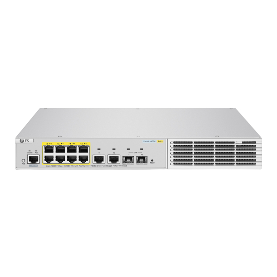
- Page 4 S3410-24TS-P CONSOLE S3410-24TS-P PoE+ STATUS M1 M2 PWR1 PWR2 PoE CONSOLE SFP+ Green=1000M Yellow=10/100M On=Link Flashing=ACT PoE LED:Green=Good Supply Yellow=Over Load RJ45 RJ45/SFP Combo SFP+ S3410-48TS-P CONSOLE SFP+ RJ45 RJ45/SFP Combo Ports Description RJ45 10/100/1000BASE-T ports for Ethernet connection RJ45/SFP Combo One RJ45 port and one SFP slot, with one port active at a time SFP+ SFP+ ports for 1/10G connection...
- Page 5 Front Panel Buttons S3410-10TF-P RESET Button Description Switch the display mode between PoE mode and switch mode. Restart: Press and hold the RESET button for more than five seconds, RESET and then wait for ten seconds. S3410-24TS-P S3410-24TS-P PoE+ STATUS M1 M2 PWR1 PWR2 PoE SFP+ CONSOLE...
- Page 6 Back Panels S3410-10TF-P Cable Clamps Holes Power Supply Grounding Point S3410-24TS-P/S3410-48TS-P Module1 Module2 Input Input Power Output Output Expansion Module Slot Dual Power Supplies Grounding Point Front Panel LEDs S3410-10TF-P RJ45 STATUS PoE(1-8)
- Page 7 S3410-24TS-P PWR2 RJ45 SFP+ STATUS S3410-24TS-P PoE+ STATUS M1 M2 PWR1 PWR2 PoE CONSOLE SFP+ Green=1000M Yellow=10/100M On=Link Flashing=ACT PoE LED:Green=Good Supply Yellow=Over Load PoE(1-24) PWR1 S3410-48TS-P PWR2 STATUS RJ45 SFP+ PoE(1-48) PWR1 LEDs Status Description Off Switch is not receiving power. System is being initialized.
- Page 8 LEDs Status Description Solid Green Indicates the switching state. Solid Yellow Indicates the PoE state. Off The port is not connected. Solid Green The port is connected at 1000 Mbps. RJ45 Blinking Green The port is receiving or transmitting traffic at 1000 Mbps. Solid Yellow The port is connected at 10/100 Mbps.
- Page 9 Installation Requirements Before you begin the installation, make sure that you have the followings: Phillips screwdriver. Standard-sized, 19" wide rack with a minimum of 1U height available. Category 5e or higher RJ-45 Ethernet cables, fiber optical cables and console cable for connecting network devices.
- Page 10 Mounting the Switch Desk Mounting 1. Attach four rubber pads to the bottom. 2. Place the chassis on a desk. Rack Mounting 1. Secure the mounting brackets to the two sides of the switch with the supplied M4 screws.
- Page 11 2. Attach the switch to the rack using four M6 screws and cage nuts. Wall Mounting 1. Secure the mounting brackets to the two sides of the switch with the supplied M4 screws.
- Page 12 2. Use the expansion screws to securely attach the mounting brackets on the wall. NOTE: Suitable for mounting on concrete or other non-combustible surface only. Installing the Power Supply Module S3410-24TS-P/S3410-48TS-P...
- Page 13 1. Take a new power module out of the package and confirm the input mode and the input parameters of the power module match the requirements. 2. Remove the old power module and take the plane printed with power information as the top panel of the power module.
- Page 14 Connecting the Power 1. Plug the AC power cord into the power port on the back of the switch. 2. Connect the other end of the power cord to an AC power source. WARNING: Do not install power cable while the power is on. Connecting the RJ45 Ports 1.
- Page 15 Connecting the SFP/SFP+ Ports 1. Plug the compatible SFP/SFP+ transceiver into the SFP/SFP+ port. 2. Connect a fiber optic cable to the fiber transceiver. Then connect the other end of the cable to another fiber device. WARNING: Laser beams will cause eye damage. Do not look into bores of optical modules or optical fibers without eye protection.
- Page 16 Stacking the Switches S3410-24TS-P/S3410-48TS-P The S3410-24TS-P/S3410-48TS-P switches support stacking up to 4 switches between the same series together. The switches can be physically stacked using optical fiber cables connected to SFP+ transceivers or 10G Direct Attach Cables (DAC). S3410-24TS-P switch supports ports 25 & 26 for physical stacking.
- Page 17 Configuring the Switch Using the Web-based Interface Step 1: Connect the computer to any Ethernet port of the switch using the network cable. Step 2: Set the IP address of the computer to 192.168.1.x. ("x" is any number from 2 to 254.). Set the subnet mask of the computer to 255.255.255.0.
- Page 18 Configuring the Switch Using the Console Port Step 1: Connect a computer to the switch's console port using the console cable. Step 2: Start the terminal simulation software such as HyperTerminal on the computer. Step 3: Set the parameters of the HyperTerminal: 9600 bits per second, 8 data bits, no parity, 1 stop bit and no flow control.
- Page 19 Product Warranty FS ensures our customers that any damage or faulty items due to our workmanship, we will offer a free return within 30 Days from the day you receive your goods. This excludes any custom made items or tailored solutions.
- Page 20 Einführung Vielen Dank, dass Sie sich für Managed PoE+-Switches der S3410-Serie entschieden haben. Diese Anleitung soll Sie mit dem Aufbau des Switches vertraut machen und beschreibt, wie Sie den Switch in Ihrem Netzwerk einsetzen. S3410-10TF-P S3410-24TS-P PoE+ STATUS M1 M2 PWR1 PWR2 PoE S3410-24TS-P CONSOLE SFP+...
- Page 21 S3410-24TS-P/S3410-48TS-P Netzkabel x2 Erdungskabel x1 Gummipad x4 Montagehalterung x2 M4-Schraube x8 NINWEIS: Die PoE+-Switches der Serie S3410 werden mit Staubschutzkappen geliefert. Bewahren Sie die Staubschutzkappen ordnungsgemäß auf und verwenden Sie sie zum Schutz ungenutzter optischer Ports. Hardware-Übersicht Ports an der Vorderseite S3410-10TF-P CONSOLE RJ45...
- Page 22 S3410-24TS-P CONSOLE S3410-24TS-P PoE+ STATUS M1 M2 PWR1 PWR2 PoE CONSOLE SFP+ Green=1000M Yellow=10/100M On=Link Flashing=ACT PoE LED:Green=Good Supply Yellow=Over Load RJ45 RJ45/SFP Combo SFP+ S3410-48TS-P CONSOLE SFP+ RJ45 RJ45/SFP Combo Ports Beschreibung RJ45 10/100/1000BASE-T Ports für Ethernet-Anschluss RJ45/SFP Combo Ein RJ45-Port und ein SFP-Slot, wobei jeweils ein Port aktiv ist SFP+ SFP+-Ports für 1/10G-Verbindung...
- Page 23 Tasten an der Vorderseite S3410-10TF-P RESET Taste Beschreibung Umschalten des Anzeigemodus zwischen PoE-Modus und Switch-Modus. Neustart: Halten Sie die RESET-Taste mehr als fünf Sekunden lang RESET gedrückt und warten Sie dann zehn Sekunden lang. S3410-24TS-P S3410-24TS-P PoE+ STATUS M1 M2 PWR1 PWR2 PoE SFP+ CONSOLE Green=1000M Yellow=10/100M...
- Page 24 Rückseite S3410-10TF-P Löcher für Kabelklemmen Stromzufuhr Erdungspunkt S3410-24TS-P/S3410-48TS-P Module1 Module2 Input Input Power Output Output Steckplatz für Erweiterungsmodule Duale Stromversorgungen Erdungspunkt LEDs an der Vorderseite S3410-10TF-P RJ45 STATUS PoE(1-8)
- Page 25 S3410-24TS-P PWR2 RJ45 SFP+ STATUS S3410-24TS-P PoE+ STATUS M1 M2 PWR1 PWR2 PoE SFP+ CONSOLE Green=1000M Yellow=10/100M On=Link Flashing=ACT PoE LED:Green=Good Supply Yellow=Over Load PoE(1-24) PWR1 S3410-48TS-P PWR2 STATUS RJ45 SFP+ PoE(1-48) PWR1 LEDs Status Beschreibung Switch wird nicht mit Strom versorgt. Das System wird gerade initialisiert.
- Page 26 LEDs Status Beschreibung Zeigt den Switch-Status an. Leuchtet Grün Zeigt den PoE-Status an. Leuchtet Gelb Der Port ist nicht angeschlossen. Leuchtet Grün Der Port ist mit 1000 Mbit/s verbunden. RJ45 Blinkt Grün Der Port empfängt oder sendet Datenverkehr mit 1000 Mbit/s. Leuchtet Gelb Der Port ist mit 10/100 Mbit/s verbunden.
- Page 27 Installationsvoraussetzungen Bevor Sie mit der Installation beginnen, vergewissern Sie sich, dass Sie über die folgenden Dinge verfügen: Kreuzschlitzschraubendreher. Ein 19"-Rack in Standardgröße mit einer Mindesthöhe von 1HE. RJ-45-Ethernet-Kabel der Kategorie 5e oder höher, Glasfaserkabel und Konsolenkabel für den Anschluss von Netzwerkgeräten. Standortumgebung: Betreiben Sie das Gerät nicht in einem Bereich, in dem die Umgebungstemperatur 50°C überschreitet.
- Page 28 Montage des Switches Montage auf einem Tisch 1. Bringen Sie vier Gummipads an der Unterseite an. 2. Stellen Sie das Gehäuse auf den Tisch. Rack-Montage 1. Befestigen Sie die Montagehalterungen mit den mitgelieferten M4-Schrauben an den beiden Seiten des Switches.
- Page 29 2. Befestigen Sie den Switch mit vier M6-Schrauben und Käfigmuttern am Rack. Wandmontage 1. Befestigen Sie die Montagehalterungen mit den mitgelieferten M4-Schrauben an den beiden Seiten des Switches.
- Page 30 2. Verwenden Sie die Spreizschrauben, um die Montagehalterungen sicher an der Wand zu befestigen. HINWEIS: Nur für die Montage auf Beton oder anderen nicht brennbaren Oberflächen geeignet. Installation des Stromversorgungsmoduls S3410-24TS-P/S3410-48TS-P...
- Page 31 1. Nehmen Sie ein neues Stromversorgungsmodul aus der Verpackung und überprüfen Sie, ob der Eingangsmodus und die Eingangsparameter des Stromversorgungsmoduls den Anforderungen entsprechen. 2. Entfernen Sie das alte Leistungsmodul und nehmen Sie die mit Leistungsinformationen bedruckte Fläche als Oberseite des Leistungsmoduls. Halten Sie den Griff des Leistungsmoduls mit einer Hand fest, und halten Sie das Ende des Leistungsmoduls mit der anderen Hand.
- Page 32 Anschließen der Stromversorgung 1. Stecken Sie das Netzkabel in den Port auf der Rückseite des Switches. 2. Schließen Sie das andere Ende des Netzkabels an eine Netzstromquelle an. WARNUNG: Schließen Sie das Netzkabel nicht an, wenn das Gerät eingeschaltet ist. Anschließen der RJ45-Ports 1.
- Page 33 Anschließen der SFP/SFP+-Ports 1. Stecken Sie den kompatiblen SFP/SFP+-Transceiver in den SFP/SFP+-Port. 2. Schließen Sie ein Glasfaserkabel an den Glasfasertransceiver an. Schließen Sie dann das andere Ende des Kabels an ein anderes Glasfasergerät an. WARNUNG: Laserstrahlen können zu Augenschäden führen. Schauen Sie nicht ohne Augenschutz in die Bohrungen von optischen Modulen oder Glasfasern.
- Page 34 Stacking der Switches S3410-24TS-P/S3410-48TS-P Die S3410-24TS-P/S3410-48TS-P-Switches unterstützen das Stacking von bis zu 4 Switches der gleichen Serie untereinander. Die Switches können physisch mit Glasfaserkabeln gestapelt werden, die an SFP+-Transceiver oder 10G Direct Attach Kabel (DAC) angeschlossen sind. Der S3410-24TS-P Switch unterstützt die Ports 25 und 26 für physisches Stacking. Der S3410-48TS-P Switch unterstützt Port 49 und 50 für physisches Stacking.
- Page 35 Konfiguration des Switches Konfigurieren des Switches über das webbasierte Interface Schritt 1: Schließen Sie den Computer über das Netzwerkkabel an einen beliebigen Ethernet Port des Switches an. Schritt 2: Stellen Sie die IP-Adresse des Computers auf 192.168.1.x ein. ("x" ist eine beliebige Zahl von 2 bis 254.).
- Page 36 Konfigurieren des Switches mithilfe des Console-Ports Schritt 1: Schließen Sie einen Computer über das Konsolenkabel an den Console-Port des Switches an. Schritt 2: Starten Sie die Terminalsimulationssoftware, z. B. HyperTerminal, auf dem Computer. Schritt 3: Stellen Sie die Parameter von HyperTerminal ein: 9600 Bits pro Sekunde, 8 Datenbits, keine Parität, 1 Stoppbit und keine Flow Control.
- Page 37 Produktgarantie FS garantiert allen Kunden, dass wir bei Schäden oder fehlerhaften Artikeln, die auf unsere Verarbeitung zurückzuführen sind, eine kostenlose Rückgabe innerhalb von 30 Tagen ab dem Tag des Erhalts der Ware anbieten. Dies gilt nicht für maßgefertigte Artikel oder maßgeschneiderte Lösungen.
- Page 38 Introduction Merci d'avoir choisi les Switchs Manageables PoE+ de la Série S3410. Ce guide est conçu pour vous familiariser avec la configuration du switch et décrit comment procéder à son déploiement. S3410-10TF-P S3410-24TS-P PoE+ STATUS M1 M2 PWR1 PWR2 PoE S3410-24TS-P CONSOLE SFP+...
- Page 39 S3410-24TS-P/S3410-48TS-P Câble d'Alimentation x2 Câble de Mise à la Terre x1 Coussin en Caoutchouc x4 Support de Montage x2 Vis M4 x8 NOTE : Les switchs PoE+ de la série S3410 sont livrés avec des capuchons anti-poussière. Conservez ces capuchons correctement et utilisez-les pour protéger les ports optiques inactifs.
- Page 40 S3410-24TS-P CONSOLE S3410-24TS-P PoE+ STATUS M1 M2 PWR1 PWR2 PoE CONSOLE SFP+ Green=1000M Yellow=10/100M On=Link Flashing=ACT PoE LED:Green=Good Supply Yellow=Over Load RJ45 RJ45/SFP Combo SFP+ S3410-48TS-P CONSOLE SFP+ RJ45 RJ45/SFP Combo Ports Description RJ45 Ports 10/100/1000BASE-T pour connexion Ethernet RJ45/SFP Combo Un port RJ45 et une rainure SFP, dont un seul port est actif à...
- Page 41 Boutons du Panneau Frontal S3410-10TF-P RESET Boutons Description Changement entre le mode PoE et mode switch. Redémarrage : Appuyez sur le bouton RESET pendant plus de cinq RESET secondes, puis attendez dix secondes. S3410-24TS-P S3410-24TS-P PoE+ STATUS M1 M2 PWR1 PWR2 PoE SFP+ CONSOLE Green=1000M Yellow=10/100M...
- Page 42 Panneau Arrière S3410-10TF-P Orifices pour Serre-câbles Alimentation Électrique Point de Mise à la Terre S3410-24TS-P/S3410-48TS-P Module1 Module2 Input Input Power Output Output Rainure pour Module d'Extension Blocs d'Alimentation Doubles Point de Mise à la Terre Indicateurs LED du Panneau Frontal S3410-10TF-P RJ45 STATUS...
- Page 43 S3410-24TS-P PWR2 RJ45 SFP+ STATUS S3410-24TS-P PoE+ STATUS M1 M2 PWR1 PWR2 PoE SFP+ CONSOLE Green=1000M Yellow=10/100M On=Link Flashing=ACT PoE LED:Green=Good Supply Yellow=Over Load PoE(1-24) PWR1 S3410-48TS-P PWR2 STATUS RJ45 SFP+ PoE(1-48) PWR1 Indicateurs Statut Description Éteint Le switch ne reçoit pas de courant. Le système est en cours d'initialisation.
- Page 44 Indicateurs Statut Description Indique l'état de commutation. Vert Indique l'état du PoE. Jaune Éteint Le port n'est pas connecté. Le port est connecté à 1000Mbps. Vert RJ45 Vert Clignotant Le port reçoit ou transmet du trafic à 1000Mbps. Jaune Le port est connecté à 10/100Mbps. Jaune Clignotant Le port reçoit ou transmet du trafic à...
- Page 45 Exigences d'Installation Avant de commencer l'installation, assurez-vous que vous disposez des éléments suivants : Tournevis phillips. Rack de taille standard, 19" de large, avec une hauteur minimum de 1U. Câbles Ethernet RJ-45 de catégorie 5e ou supérieure, câbles à fibre optique et câble de console pour la connexion des périphériques réseau.
- Page 46 Installation du Switch Installation sur Support 1. Fixez quatre coussins en caoutchouc à la base. 2. Placez le châssis sur un support. Installation en Rack 1. Fixez les supports de montage aux deux côtés du switch avec les vis M4 fournies.
- Page 47 2. Fixez le switch au rack à l'aide de quatre vis M6 et d'écrous à cage. Installation Murale 1. Fixez les supports de montage aux deux côtés du switch à l'aide des vis M4 fournies.
- Page 48 2. Utilisez les vis d'expansion pour fixer solidement les supports de montage au mur. NOTE : Ne convient que pour un montage sur du béton ou toute autre surface non inflammable. Installation du Module d'Alimentation S3410-24TS-P/S3410-48TS-P...
- Page 49 1. Retirez le module d'alimentation de son emballage et vérifiez que le mode et paramètres d'entrée du module d'alimentation correspondent aux exigences. 2. Retirez le module d'alimentation actuel et saisissez le panneau qui indique les informations relatives à l'alimentation comme le panneau supérieur du module d'alimentation. Saisissez la poignée du module d'alimentation d'une main, et l'extrémité...
- Page 50 Connexion de l'Alimentation 1. Branchez le câble d'alimentation CA dans le port d'alimentation situé à l'arrière du switch. 2. Connectez l'autre extrémité du câble d'alimentation à une source de courant alternatif. AVERTISSEMENT : Ne pas installer le câble d'alimentation lorsque l'appareil est sous tension. Connexion des Ports RJ45 1.
- Page 51 Connexion des Ports SFP/SFP+ 1. Branchez l'émetteur-récepteur SFP/SFP+ compatible sur le port SFP/SFP+. 2. Connectez un câble en fibre optique à l'émetteur-récepteur. Puis connectez l'autre extrémité du câble à un autre appareil à fibre. AVERTISSEMENT : Les faisceaux laser peuvent causer des lésions oculaires. Ne pas regarder dans les orifices des modules optiques ou des fibres optiques sans protection oculaire.
- Page 52 Empilage des Switchs S3410-24TS-P/S3410-48TS-P Les switchs S3410-24TS-P/S3410-48TS-P permettent un empilage d'un maximum de 4 switchs de la même série. Le switch peut être empilé physiquement à l'aide de câbles en fibre optique connectés à des émetteurs-récepteurs SFP+ ou à des Câbles à Attache Directe (DAC) 10G. Les ports 25 et 26 du switch S3410-24TS-P sont utilisés pour l'empilage physique.
- Page 53 Configuration du Switch Configuration du Switch à l'Aide de l'Interface Web Étape 1 : Connectez l'ordinateur au port de gestion du switch à l'aide du câble réseau. Étape 2 : Définissez l'adresse IP de l'ordinateur sur 192.168.1.x. ("x" est un nombre quelconque compris entre 2 et 254).
- Page 54 Configuration du Switch à l'Aide du Port Console Étape 1 : Connectez un ordinateur au port de console du switch à l'aide du câble de console. Étape 2 : Démarrez le logiciel HyperTerminal sur l'ordinateur. Étape 3 : Réglez les paramètres de l'HyperTerminal : 9600 bits par seconde, 8 bits de données, pas de parité, 1 bit d'arrêt et pas de contrôle de flux.
- Page 55 Garantie du Produit FS garantit à ses clients que tout article endommagé ou défectueux dû à sa fabrication peut être retourné gratuitement dans les 30 Jours suivant la réception de la marchandise. Ceci exclut les articles fabriqués sur mesure ou les solutions personnalisées.
- Page 56 Any changes or modifications not expressly approved by the grantee of this device could void the user's authority to operate the equipment. Responsible party (only for FCC matter) FS.COM Inc. 380 Centerpoint Blvd, New Castle, DE 19720, United States https://www.fs.com...
- Page 57 Die FS.COM GmbH erklärt hiermit, dass dieses Gerät mit der Richtlinie 2014/30/EU und 2014/35/EU konform ist. Eine Kopie der EU-Konformitätserklärung finden Sie unter www.fs.com/de/company/quality_control.html. FS.COM GmbH déclare par la présente que cet appareil est conforme à la Directive 2014/30/UE et 2014/35/UE. Une copie de la Déclaration UE de Conformité est disponible sur https://www.fs.com/fr/company/quality_control.html FS.COM LIMITED...