Publicité
Les langues disponibles
Les langues disponibles
Liens rapides
1
2
3
4
5
CON
6
7
8
9
10
11
12
13
14
15
16
MGM T
S58 50- 24X
MG
17
18
19
20
21
22
23
24
SYS
ID MGM
T
25
26
100G
1
2
3
4
Brea kout
S5850-24XMG
MANAGED L3 ENTERPRISE SWITCH
Managed L3 Enterprise Switch
SWITCH MANAGEABLE L3 POUR ENTREPRISE
Quick Start Guide
V1.0
Quick-Start Anleitung
Guide de Démarrage Rapide
Publicité

Manuels Connexes pour FS S5850-24XMG


Sommaire des Matières pour FS S5850-24XMG
- Page 1 MGM T S58 50- 24X ID MGM 100G Brea kout S5850-24XMG MANAGED L3 ENTERPRISE SWITCH Managed L3 Enterprise Switch SWITCH MANAGEABLE L3 POUR ENTREPRISE Quick Start Guide V1.0 Quick-Start Anleitung Guide de Démarrage Rapide...
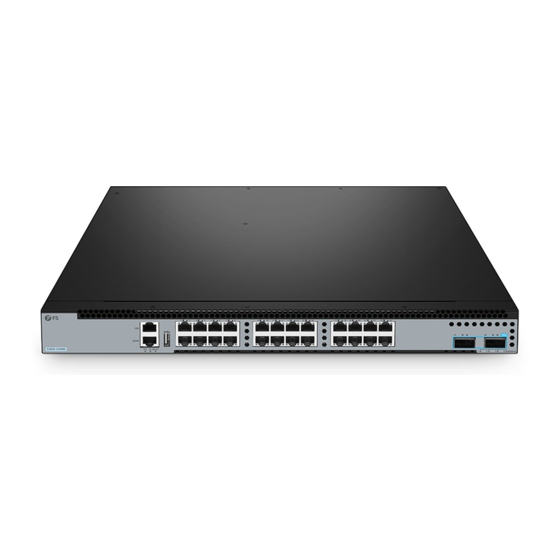
- Page 2 Introduction Thank you for choosing S5850-24XMG switch. This guide is designed to familiarize you with the layout of the switch and describes how to deploy the switch in your network. 100G MGMT S5850-24XMG ID MGMT Breakout S5850-24XMG Accessories Power Cord x2...
- Page 3 Hardware Overview Front Panel Ports RJ45 QSFP28 100G MGMT S5850-24XMG ID MGMT Breakout MGMT Ports Description An RJ45 console port for serial management MGMT An Ethernet management port A USB port for software and con guration backup and o ine software upgrade RJ45 10/100/1000/2.5G/5G/10GBASE-T ports for Ethernet connection...
- Page 4 LEDs State Description On(L) Port is linked. Blinking(L) Port is receiving or transmitting packets. RJ45 O (L) Port is not linked. Amber(R) The rate hasn’t reached the maximum. Green(R) The rate has reached the maximum. O (R) Port is not linked. Green Port is linked at 40/100G.
- Page 5 Site Environment Do not operate it in an area that exceeds an ambient temperature of 45°C. The installation site must be well ventilated. Ensure that there is adequate air ow around the switch. Be sure that the switch is level and stable to avoid any hazardous conditions. Do not install the equipment in a dusty environment.
- Page 6 Rack Mounting 100 G Bre ako ut 1. Fix front mounting brackets and silding rails to the two sides of the switch with screws. MGM T S58 50-2 4XM ID MGM 100G Break out 2. Push back mounting brackets onto the silding rails.
- Page 7 3. Attach the switch to the rack with screws and cage nuts. Grounding the Switch 1. Connect one end of the grounding cable to a proper earth ground, such as the rack in which the switch is mounted. 2. Secure the grounding lug to the grounding point on the back panel of the switch with the washer and screws.
- Page 8 Connecting the Power CO N MG MT S5 85 0-2 4X ID MG MT 1. Plug the AC power cord into the power port on the back of the switch. 2. Connect the other end of the power cord to an AC power source. WARNING: Do not install power cable while the power is on.
- Page 9 Connecting the QSFP28 Ports 100 G Bre ako ut 1. Plug the compatible QSFP+ transceiver into the QSFP28 port. 2. Connect a ber optic cable to the transceiver, then connect the other end of the cable to another ber device. 3.
- Page 10 Connecting the Management Ports Connecting the Console Port MGM T S58 50-2 4XM ID MGM 1. Insert the RJ45 connector into the RJ45 console port on the switch. 2. Connect the DB9 female connector of the console cable to the serial port on the computer. Connecting the MGMT Port CO N MG MT...
- Page 11 Con guring the Switch Con guring the Switch Using the Web-based Interface Step1: Connect the computer to the Management port of the switch using the network cable. Step 2: Set the IP address of the computer to 192.168.1.x. ("x" is any number from 2 to 254.). Set the subnet mask of the computer to 255.255.255.0.
- Page 12 Con guring the Switch Using the Console Port Step 1: Connect a computer to the console port of the switch with supplied console cable. Step 2: Start the terminal simulation software such as HyperTerminal on the computer. Step 3: Set the parameters of the HyperTerminal: 115200 bits per second, 8 data bits, no parity, 1 stop bit and no ow control.
- Page 13 Troubleshooting Loading Failure 1. Check whether the port is properly connected. If some ports are not connected, then re-connect them to ensure that connections are correct, and try to re-loading. 2. Check the loading process information displayed on the super terminal to verify whether there are input errors.
- Page 14 Product Warranty FS ensures our customers that if there are any damage or faulty items due to our workmanship, we will o er a free return within 30 Days from the day you receive your goods. This excludes any custom made items or tailored solutions.
- Page 15 Einführung Vielen Dank, dass Sie sich für den S5850-24XMG Switch entschieden haben. Diese Anleitung soll Sie mit dem Aufbau des Switches vertraut machen und erklärtt, wie Sie den Switch in Ihrem Netzwerk einsetzen. 100G MGMT S5850-24XMG ID MGMT Breakout S5850-24XMG Zubehör...
- Page 16 Hardware-Übersicht Ports an der Vorderseite RJ45 QSFP28 100G MGMT S5850-24XMG ID MGMT Breakout MGMT Port Beschreibung Ein RJ45-Console-Port für die serielle Verwaltung MGMT Ein Ethernet-Verwaltungsport Ein USB-Port für Software- und Kon gurations-Backups und O ine-Software-Upgrades RJ45 10/100/1000/2,5G/5G/10GBASE-T Ports für Ethernet-Verbindung QSFP28 QSFP28-Ports für 40/100G-Transceiver...
- Page 17 Status Beschreibung An (L) Der Port ist verbunden. Blinkt (L) Der Port empfängt oder sendet Datenpakete. RJ45 Aus (L) Der Port ist nicht verbunden. Braun (R) Die Rate hat nicht den Höchstwert erreicht. Grün (R) Die Rate hat den Höchstwert erreicht. Aus (R) Der Port ist nicht verbunden.
- Page 18 Standortumgebung Betreiben Sie das Gerät nicht in einem Bereich, in dem die Umgebungstemperatur 45°C übersteigt. Der Installationsort muss gut belüftet sein. Stellen Sie sicher, dass um den Switch herum ein ausreichender Luftstrom herrscht. Achten Sie darauf, dass der Switch eben und stabil steht, um gefährliche Bedingungen zu vermeiden. Installieren Sie das Gerät nicht in einer staubigen Umgebung.
- Page 19 Rack-Montage 100 G Bre ako ut 1. Befestigen Sie die Montagehalterungen für die Vorderseite und die Gleitschienen mit Schrauben an den beiden Seiten des Switches. MGM T S58 50-2 4XM ID MGM 100G Break out 2. Schieben Sie die Halterungen zurück auf die Gleitschienen.
- Page 20 3. Befestigen Sie den Switch mit Schrauben und Kä gmuttern am Rack. Erdung des Switches CO N MG MT S5 85 0-2 4X ID MG MT 1. Schließen Sie ein Ende des Erdungskabels an eine geeignete Erdung an, z. B. an das Rack, in dem der Switch montiert ist.
- Page 21 Anschließen der Stromversorgung 1. Stecken Sie das Netzkabel in den Netzanschluss an der Rückseite des Switches. 2. Schließen Sie das andere Ende des Netzkabels an eine Netzstromquelle an. WARNUNG: Installieren Sie das Netzkabel nicht, wenn der Switch eingeschaltet ist. Anschließen der RJ45-Ports 100 G Bre ako ut 1.
- Page 22 Anschließen der QSFP28-Ports 100 G Bre ako ut 1. Stecken Sie den kompatiblen QSFP+-Transceiver in den QSFP28-Port. 2. Schließen Sie ein Glasfaserkabel an den Transceiver an und verbinden Sie dann das andere Ende des Kabels mit einem anderen Glasfasergerät. 3. Oder schließen Sie das DAC/AOC-Kabel direkt an den QSFP28-Port an. VORSICHT: Laserstrahlen können Augenschäden verursachen.
- Page 23 Anschluss der Management-Ports Anschließen des Console-Ports MGM T S58 50-2 4XM ID MGM 1. Stecken Sie den RJ45-Stecker in den RJ45-Console-Port des Switches. 2. Verbinden Sie die DB9-Buchse des Console-Kabels mit dem seriellen Port des Computers. Anschließen des MGMT-Ports CO N MG MT S5 85 0-2 4X ID MG MT...
- Page 24 Kon gurieren des Switches Kon gurieren des Switches über das webbasierte Interface Schritt 1: Schließen Sie den Computer mit dem Netzwerkkabel an den Verwaltungsport des Switches an Schritt 2: Stellen Sie die IP-Adresse des Computers auf 192.168.1.x ein. ("x" ist eine beliebige Zahl von 2 bis 254.).
- Page 25 Kon gurieren des Switches über den Console-Port Schritt 1: Schließen Sie einen Computer mit dem mitgelieferten Console-Kabel an den Console-Port des Switches an. Schritt 2: Starten Sie die Terminalsimulationssoftware, z. B. HyperTerminal, auf dem Computer. Schritt 3: Stellen Sie die Parameter von HyperTerminal ein: 115200 Bits pro Sekunde, 8 Datenbits, keine Parität, 1 Stoppbit und keine Flusskontrolle.
- Page 26 Fehlersuche Fehlgeschlagenes Laden 1. Prüfen Sie, ob der Port richtig angeschlossen ist. Wenn einige Ports nicht angeschlossen sind, schließen Sie sie erneut an, um sicherzustellen, dass die Verbindungen korrekt sind, und versuchen Sie, erneut zu laden. 2. Überprüfen Sie die auf dem Superterminal angezeigten Informationen zum Ladevorgang, um festzustellen, ob es Eingabefehler gibt.
- Page 27 Produktgarantie FS garantiert seinen Kunden, dass wir im Falle von Schäden oder fehlerhaften Artikeln, die auf unsere Verarbeitung zurückzuführen sind, eine kostenlose Rückgabe innerhalb von 30 Tagen nach Erhalt der Ware anbieten. Dies gilt nicht für Sonderanfertigungen oder maßgeschneiderte Lösungen.
- Page 28 Introduction Nous vous remercions d'avoir choisi le switch S5850-24XMG. Ce guide est conçu pour vous puissiez vous familiariser avec la con guration du switch et décrit comment procéder à son déploiement. 100G MGMT S5850-24XMG ID MGMT Breakout S5850-24XMG Accessoires Câble d'Alimentation x2 Câble de Console x1...
- Page 29 Aperçu du Matériel Ports du Panneau Frontal RJ45 QSFP28 100G MGMT S5850-24XMG ID MGMT Breakout MGMT Ports Description Un port console RJ45 pour la gestion en série MGMT Un port de gestion Ethernet Un port USB pour la sauvegarde du logiciel, la con guration et la mise à...
- Page 30 Statut Description Allumé (L) Le port est relié. Clignotant (L) Le port reçoit ou transmet des paquets. RJ45 Éteint (L) Le port n'est pas relié. Jaune (R) Le taux n'a pas atteint le maximum. Vert (R) Le taux a atteint le maximum. Éteint (R) Le port n'est pas relié.
- Page 31 Site de l'Installation Ne pas installer l'appareil dans un endroit où la température ambiante dépasse 45°C. Le site d'installation doit être bien ventilé. Veillez à ce qu'il y ait une circulation d'air su sante autour du switch. Assurez-vous que le switch soit à niveau et stable pour éviter tout risque. Ne pas installer l'équipement dans un environnement poussiéreux.
- Page 32 Montage en Rack 100 G Bre ako ut 1. Fixez les supports de montage frontaux et les rails coulissants aux deux côtés du commutateur à l'aide de vis. MGM T S58 50-2 4XM ID MGM 100G Break out 2. Faites glisser les supports de montage sur les rails coulissants.
- Page 33 3. Fixez le commutateur au rack à l'aide de vis et d'écrous à cage. Mise à la Terre du Switch CO N MG MT S5 85 0-2 4X ID MG MT 1. Connectez une extrémité du câble de mise à la terre à une mise à la terre appropriée, telle que le rack dans lequel le switch est installé.
- Page 34 Connexion de l'Alimentation CO N MG MT S5 85 0-2 4X ID MG MT 1. Branchez le câble d'alimentation CA dans le port d'alimentation situé sur le panneau arrière du switch. 2. Connectez l'autre extrémité du câble d'alimentation à une source de courant alternatif. ATTENTION : Ne pas installer les câbles d'alimentation lorsque l'appareil est sous tension.
- Page 35 Connexion des Ports QSFP28 100 G Bre ako ut 1. Branchez le module QSFP+ compatible dans le port QSFP28. 2. Connectez un câble à bre optique au module, puis connectez l'autre extrémité du câble à un autre dispositif à bre. 3.
- Page 36 Connexion des Ports de Gestion Connexion du Port Console ID MGM T S58 00-4 8MB 1. Insérez le connecteur RJ45 dans le port de console RJ45 du switch. 2. Connectez le connecteur femelle DB9 du câble de la console au port série de l'ordinateur. Connexion du Port MGMT CO N MG MT...
- Page 37 Con guration du Switch Con guration du Switch à l'Aide de l'Interface Web Étape 1 : Connectez votre ordinateur à n'importe quel port Ethernet du switch avec le câble réseau. Étape 2 : Dé nissez l'adresse IP de l'ordinateur sur 192.168.1.x. ("x" est un nombre quelconque compris entre 2 et 254.).
- Page 38 Con guration du Switch à l'Aide du Port Console Étape 1 : Connectez un ordinateur au port de console du switch à l'aide du câble de console fourni. Étape 2 : Démarrez le logiciel HyperTerminal sur l'ordinateur. Étape 3 : Dé nissez les paramètres de l'HyperTerminal : 115200 bits par seconde, 8 bits de données, pas de parité, 1 bit d'arrêt et pas de contrôle de ux.
- Page 39 Dépannage Échec du Chargement 1. Véri ez si le port est correctement connecté. Si certains ports ne sont pas connectés, reconnectez-les pour vous assurer que les connexions sont correctes, puis essayez de recharger. 2. Véri ez les informations sur le processus de chargement a chées sur le super terminal pour véri er s'il y a des erreurs de saisie.
- Page 40 Garantie du Produit FS garantit à ses clients qu'en cas de dommages ou d'articles défectueux dus à sa fabrication, un retour gratuit pourra être e ectué dans les 30 Jours suivant la réception de la marchandise. Ceci exclut les articles fabriqués sur mesure ou les solutions personnalisées.
- Page 41 Any changes or modi cations not expressly approved by the grantee of this device could void the user's authority to operate the equipment. Responsible party (only for FCC matter) FS.COM Inc. 380 Centerpoint Blvd, New Castle, DE 19720, United States https://www.fs.com...
- Page 42 Die FS.COM GmbH erklärt hiermit, dass dieses Gerät mit der Richtlinie 2014/30/EU und 2014/35/EU. Eine Kopie der EU-Konformitätserklärung nden Sie unter www.fs.com/de/company/quality_control.html. FS.COM GmbH déclare par la présente que cet appareil est conforme à la Directive 2014/30/UE et 2014/35/UE. Une copie de la Déclaration UE de Conformité est disponible sur https://www.fs.com/fr/company/quality_control.html FS.COM LIMITED...
- Page 43 Q.C. PASSED Copyright © 2022 FS.COM All Rights Reserved.