Table des Matières
Publicité
Les langues disponibles
Les langues disponibles
Liens rapides
2
4
6
8
10
12
14
1
3
5
7
9
11
13
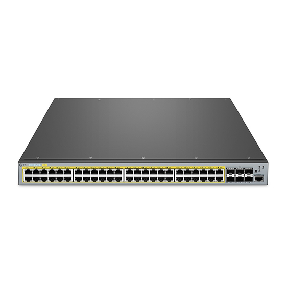
S5500-48T6SP-R
48 PORT GIGABIT STACKABLE L3
POE+ MANAGED SWITCH
STAPELBARER 48-PORT GIGABIT L3 POE+ MANAGED SWITCH
SWITCH MANAGEABLE L3 POE+ EMPILABLE GIGABIT 48 PORTS
Quick Start Guide
Quick Start Anleitung
Guide de Démarrage Rapide
16
18
20
22
24
26
28
30
15
17
19
21
23
25
27
29
V1.0
32
34
36
38
40
42
44
46
31
33
35
37
39
41
43
45
48
P o E
S 5 5 0 0 -4
8 T 8 S P
PO E
CO N SO
LE
SY S
SW A P
47
PW R
Publicité
Table des Matières

Manuels Connexes pour FS S5500-48T6SP-R


Sommaire des Matières pour FS S5500-48T6SP-R
- Page 1 8 T 8 S P PO E CO N SO SY S SW A P PW R S5500-48T6SP-R 48 PORT GIGABIT STACKABLE L3 POE+ MANAGED SWITCH STAPELBARER 48-PORT GIGABIT L3 POE+ MANAGED SWITCH SWITCH MANAGEABLE L3 POE+ EMPILABLE GIGABIT 48 PORTS Quick Start Guide V1.0...
-
Page 2: Accessories
Introduction Thank you for choosing FS S5500-48T6SP-R PoE+ Switch. This guide is designed to familiarize you with the layout of the switch and describes how to deploy the switch in your network. S5500-48T6SP-R PoE+ S5500-48T6SP-R SWAP SWAP S5500-48T6SP-R Accessories Power Cord x2... - Page 3 Ports Description RJ45 10/100/1000BASE-T ports for Ethernet connection SFP+ Hot swap SFP+ ports for 1/10G connection A baud rate of 9600bps Front Panel Button S5500-48T6SP-R PoE+ SWAP SWAP Buttons Description SWAP Swap function, used to switch POE indication. Front Panel LEDs...
-
Page 4: Back Panel
Back Panel Grounding Point INPUT INPUT OUTPUT OUTPUT PWR2 PWR1 100-240Vac 50/60Hz 7-3.5A 100-240Vac 50/60Hz 7-3.5A Dual Power Site Environment Make sure that the site environment is well-ventilated, the heat of electrical devices is well-discharged and sufficient air circulation is provided for device cooling. Avoid to damage devices by following the electrostatic discharge prevention procedure. -
Page 5: Rack Mounting
Rack Mounting 1. Fix the mounting brackets to the two sides of the switch with six M3 screws. P o E S 5 5 0 0 -4 8 T 8 S P PO E CO N SO SY S SW A P PW R 2. - Page 6 Grounding the Switch 1. Connect one end of the grounding cable to a proper earth ground, such as the rack in which the switch is mounted. 2. Fix the grounding lug to the grounding point on the back panel of the switch with washers and screws. CAUTION: The earth connection cannot be removed unless all supply onnections have been disconnected.
-
Page 7: Connecting The Power
Connecting the Power 1. Plug the AC power cord into the power port on the back panel of the switch. 2. Connect the other end of the power cord to an AC power source. CAUTION: Do not install power cables while the power is on. Connecting the Console Port P o E S 5 5 0 0 - 4... - Page 8 Connecting the RJ45 Port P o E S 5 5 0 0 -4 8 T 8 S P P O E C O N SO SY S SW A P P W R 1. Connect an Ethernet cable to the RJ45 port of IP cameras, IP telephones, Access Points (AP), or other network devices.
- Page 9 Stacking the S5500-48T6SP-R PoE+ Switch The S5500-48T6SP-R PoE+ switch support stacking up to 8 units between the same model together. It can be physically stacked using optical fiber cables connected to SFP+ tranceivers, or 10G Direct Attach Cables(DAC). Any 2 SFP+ ports on rear panel of the switch can be used for physical stacking.
- Page 10 Step 4: When the login page appears, choose the language you need and enter the username and password(admin/admin). Sign in http://192.168.1.1 Your connection to this site is not private Username Password Sign in Cancel You are now ready to configure the switch. Refer to the S5500-48T6SP-R PoE+ switch Configuration Guide online for further information.
- Page 11 Configuring the Switch Using the Console Port Step 1: Connect a computer to the switch's console port with the supplied console cable. Step 2: Start the terminal simulation software such as HyperTerminal on the computer. Step 3: Configure the terminal simulation with the following parameters: 9600 bits per second 8 data bits 1 stop bit...
-
Page 12: Product Warranty
Product Warranty FS ensures our customers that if there are any damage or faulty items due to our workmanship, we will offer a free return within 3 months from the day you receive your goods. This excludes any custom made items or tailored solutions. -
Page 13: Hardware-Übersicht
Einführung Vielen Dank, dass Sie sich für den FS S5500-48T6SP-R PoE+-Switch entschieden haben. Diese Anleitung soll Sie mit dem Aufbau des Switches vertraut machen und beschreibt, wie Sie den Switch in Ihrem Netzwerk einsetzen. S5500-48T6SP-R PoE+ S5500-48T6SP-R SWAP SWAP S5500-48T6SP-R Zubehör... -
Page 14: Beschreibung
Port Beschreibung RJ45 10/100/1000BASE-T-Ports für Ethernet-Verbindung SFP+ Hot-Swap-SFP+-Ports für 1/10G-Verbindungen Baudrate von 9600bps Taste auf der Vorderseite S5500-48T6SP-R PoE+ SWAP SWAP Taste Beschreibung SWAP Swap-Funktion, zum Umschalten der PoE-Anzeige. LEDs an der Vorderseite S5500-48T6SP-R PoE+ SWAP RJ45 Status Beschreibung Der Switch ist eingeschaltet. -
Page 15: Montage Des Switches
Rückseite Erdungspunkt INPUT INPUT OUTPUT OUTPUT PWR2 PWR1 100-240Vac 50/60Hz 7-3.5A 100-240Vac 50/60Hz 7-3.5A Erdungspunkt Standortumgebung Stellen Sie sicher, dass die Umgebung des Standorts gut belüftet ist, die Wärme der elektrischen Geräte gut abgeleitet wird und eine ausreichende Luftzirkulation zur Kühlung der Geräte gewährleistet ist. -
Page 16: Rack-Montage
Rack-Montage 1. Befestigen Sie die Montagehalterungen mit sechs M3-Schrauben an den beiden Seiten des Switches. P o E S 5 5 0 0 -4 8 T 8 S P PO E CO N SO SY S SW A P PW R 2. - Page 17 Erdung des Switchs 1. Schließen Sie ein Ende des Erdungskabels an eine geeignete Erdung an, z.B. an das Rack, in dem der Switch montiert ist. 2. Befestigen Sie die Erdungslasche mit Unterlegscheiben und Schrauben am Erdungspunkt auf der Rückseite des Switches. ACHTUNG: Der Erdungsanschluss kann nur entfernt werden, wenn alle Versorgungsanschlüsse getrennt wurden.
-
Page 18: Anschließen Der Stromversorgung
Anschließen der Stromversorgung 1. Schließen Sie das Netzkabel an den Netzanschluss auf der Rückseite des Switches an. 2. Schließen Sie das andere Ende des Netzkabels an eine Netzstromquelle an. ACHTUNG: Schließen Sie die Netzkabel nicht an, wenn der Switch eingeschaltet ist. Anschließen des Konsolen-Ports P o E S 5 5 0 0 - 4... -
Page 19: Anschließen Des Rj45-Ports
Anschließen des RJ45-Ports P o E S 5 5 0 0 -4 8 T 8 S P P O E C O N SO SY S SW A P P W R 1. Schließen Sie ein Ethernet-Kabel an den RJ45-Port von IP-Kameras, IP-Telefonen, Access Points (AP) oder anderen Netzwerkgeräten an. - Page 20 Stacking von S5500-48T6SP-R PoE+-Switches Der S5500-48T6SP-R PoE+-Switch unterstützt das Stacking von bis zu 8 Geräten desselben Modells. Das Stacking kann über Glasfaserkabel, die an SFP+-Tranceiver angeschlossen sind, oder über 10G Direct Attach Kabel (DAC) erfolgen. Zwei beliebige SFP+-Ports auf der Rückseite des Switches können für physisches Stacking verwendet werden.
- Page 21 Schritt 4: Wenn die Anmeldeseite erscheint, wählen Sie die gewünschte Sprache und geben Sie den Benutzernamen und das Passwort (admin/admin) ein. Sign in http://192.168.1.1 Your connection to this site is not private Username Password Sign in Cancel Jetzt können Sie den Switch konfigurieren. Weitere Informationen finden Sie online im Konfigurationshandbuch für den S5500-48T6SP-R PoE+-Switch.
- Page 22 Konfigurieren des Switches über den Konsolen-Port Schritt 1: Schließen Sie einen Computer über das mitgelieferte Konsolenkabel an den Konsolen-Port des Switches an. Schritt 2: Starten Sie die Terminal/Simulationssoftware, z.B. HyperTerminal, auf dem Computer. Schritt 3: Konfigurieren Sie die Terminalsimulation mit den folgenden Parametern: 9600 Bits pro Sekunde 8 Datenbits 1 Stoppbit...
- Page 23 Produktgarantie FS garantiert seinen Kunden, dass im Falle von Schäden oder fehlerhaften Artikeln, die auf die Verarbeitung zurückzuführen sind, eine kostenlose Rücksendung innerhalb von 3 Monaten ab dem Tag des Erhalts der Ware angeboten wird. Dies gilt nicht für maßgefertigte Artikel oder maßgeschneiderte Lösungen.
-
Page 24: Accessoires
Introduction Merci d'avoir choisi le Switch FS S5500-48T6SP-R PoE+. Ce guide est conçu pour vous puissiez vous familiariser avec la configuration du switch et décrit comment procéder à son déploiement. S5500-48T6SP-R PoE+ S5500-48T6SP-R SWAP SWAP S5500-48T6SP-R Accessoires Câble d'Alimentation x2 Câble de Supervision x1... - Page 25 Description RJ45 Ports 10/100/1000BASE-T pour la connexion Ethernet SFP+ Ports SFP+ échangeables à chaud pour une connexion 1/10G Une vitesse de transmission de 9600 bps Bouton du Panneau Frontal S5500-48T6SP-R PoE+ SWAP SWAP Buttons Description SWAP Fonction de permutation, utilisée pour commuter la fonction POE.
-
Page 26: Panneau Arrière
Panneau Arrière Erdungspunkt INPUT INPUT OUTPUT OUTPUT PWR2 PWR1 100-240Vac 50/60Hz 7-3.5A 100-240Vac 50/60Hz 7-3.5A Doppelte Leistung Site de l'Installation Assurez-vous que le site de l'installation est bien ventilé, que la chaleur des appareils électriques est bien évacuée et qu'une circulation d'air suffisante est prévue pour le refroidissement des appareils. -
Page 27: Montage En Rack
Montage en Rack 1. Fixez les supports de montage aux deux côtés du switch avec six vis M3. P o E S 5 5 0 0 -4 8 T 8 S P PO E CO N SO SY S SW A P PW R 2. -
Page 28: Mise À La Terre Du Switch
Mise à la Terre du Switch 1. Connectez une extrémité du câble de mise à la terre à une mise à la terre appropriée, telle que le rack dans lequel le switch est installé. 2. Fixez la cosse de mise à la terre au point de mise à la terre sur le panneau arrière du switch à l'aide de rondelles et de vis. -
Page 29: Connexion De L'alimentation
Connexion de l'Alimentation 1. Branchez le câble d'alimentation CA dans le port d'alimentation situé sur le panneau arrière du switch. 2. Connectez l'autre extrémité du câble d'alimentation à une source de courant alternatif. ATTENTION: Ne pas installer les câbles d'alimentation lorsque l'appareil est sous tension. Connexion du Port Console P o E S 5 5 0 0 - 4... -
Page 30: Connexion Au Port Rj45
Connexion au Port RJ45 P o E S 5 5 0 0 -4 8 T 8 S P P O E C O N SO SY S SW A P P W R 1. Connectez un câble Ethernet au port RJ45 d'une caméra IP, téléphone IP, Point d'Accès ou d'un autre périphérique réseau. - Page 31 Empilage du Switch PoE+ S5500-48T6SP-R Le switch S5500-48T6SP-R PoE+ prend en charge l'empilement de 8 unités du même modèle. Il peut être empilé physiquement à l'aide de câbles à fibre optique connectés à des modules SFP+ ou à des Câbles à Attache Directe (DAC) 10G. Les 2 ports SFP+ du panneau arrière du switch peuvent être utili sés pour l'empilage physique.
-
Page 32: Configuration Du Switch
(admin/admin). Sign in http://192.168.1.1 Your connection to this site is not private Username Password Sign in Cancel Vous pouvez maintenant configurer le switch. Reportez-vous au Guide de Configuration en ligne du switch S5500-48T6SP-R PoE+ pour plus d'informations. -
Page 33: Dépannage
Configuration du Switch à l'Aide du Port Console Étape 1: Connectez un ordinateur au port de console du switch à l'aide du câble de console fourni. Étape 2: Démarrez le logiciel HyperTerminal sur l'ordinateur. Étape 3: Configurez la simulation du terminal avec les paramètres suivants : 9600 bits par seconde 8 bits de données 1 bit d'arrêt... -
Page 34: Accès À La Page De Configuration Sur Le Web Échoué
Garantie du Produit FS garantit à ses clients qu'en cas de dommages ou d'articles défectueux dus à notre fabrication, nous offrons un retour gratuit dans un délai de 3 mois à compter du jour où vous recevez vos marchandises. Cela exclut les articles fabriqués sur mesure ou les solutions personnalisées. -
Page 35: Compliance Information
Any changes or modifications not expressly approved by the grantee of this device could void the user's authority to operate the equipment. Responsible party (only for FCC matter) FS.COM Inc. 380 Centerpoint Blvd, New Castle, DE 19720, United States https://www.fs.com... - Page 36 Die FS.COM GmbH erklärt hiermit, dass dieses Gerät mit der Richtlinie 2014/30/EU und 2014/35/EU konform ist. Eine Kopie der EU-Konformitätserklärung finden Sie unter www.fs.com/de/company/quality_control.html. FS.COM GmbH déclare par la présente que cet appareil est conforme à la Directive 2014/30/UE et 2014/35/UE. Une copie de la Déclaration UE de Conformité est disponible sur https://www.fs.com/fr/company/quality_control.html FS.COM LIMITED...