Table des Matières
Publicité
Les langues disponibles
Les langues disponibles
Liens rapides
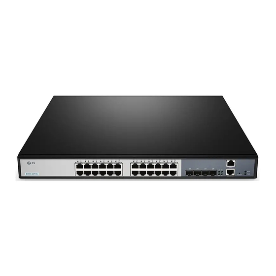
S3 90 0- 24 T4
S
S3 90 0- 24 F4
S
MANAGED L2+ GIGABIT SWITCHES
MANAGED L2+ GIGABIT SWITCHES
COMMUTATEURS L2+ GIGABIT GÉRÉS
Quick Start Guide
Quick-Start Anleitung
Guide de Démarrage Rapide
1
2
3
4
5
6
7
8
9
10
11
12
13
14
1
2
3
4
5
6
7
8
9
10
11
12
13
V3.0
15
16
17
18
19
20
21
22
23
24
25
26
14
15
16
17
18
19
20
21
22
23
24
21
22
23
27
28
MG T
26
28
SYS
25
27
RES ET
PW R
CON SOL E
MG T
CO NS OL E
SY S
PW R
25
26
27
28
24
Publicité
Table des Matières

Manuels Connexes pour FS S3900 Série


Sommaire des Matières pour FS S3900 Série
- Page 1 S3 90 0- 24 T4 MG T S3 90 0- 24 F4 RES ET PW R CON SOL E MG T CO NS OL E SY S PW R MANAGED L2+ GIGABIT SWITCHES MANAGED L2+ GIGABIT SWITCHES COMMUTATEURS L2+ GIGABIT GÉRÉS Quick Start Guide V3.0 Quick-Start Anleitung...
-
Page 2: Accessories
Introduction Thank you for choosing S3900 Series Stackable Managed Switches. This guide is designed to familiarize you with the layout of the switch and describes how to deploy the switch in your network. S3900-24T4S S3900-24T4S RESET CONSOLE CONSOLE S3900-24F4S S3900-24F4S CONSOLE S3900-48T4S Accessories... -
Page 3: Hardware Overview
Hardware Overview Front Panel Ports S3900-24T4S S3900-24T4S RESET CONSOLE RJ45 SFP+ Console S3900-24F4S MGT Console CONSOLE S3900-24F4S SFP+ S3900-48T4S MGT Console CONSOLE RJ45 SFP+ Ports Description RJ45 10/100/1000BASE-T ports for Ethernet connection SFP ports for 1G connection SFP+ SFP+ ports for 1/10G connection An out-of-band Ethernet management port Console An RJ45 console port for serial management... - Page 4 Front Panel Button S3900-24T4S S3900-24T4S RESET CONSOLE RESET Button Description Restart: Press and release the Reset button quickly. RESET Restore to Factory Default Settings: Press and hold the Reset button for more than ten seconds. Back Panels S3900-24T4S/S3900-48T4S Dual Power Supplies Grounding Point S3900-24F4S Dual Power Supplies...
-
Page 5: Front Panel Leds
Front Panel LEDs S3900-24T4S RJ45 S3900-24T4S RESET CONSOLE SFP+ S3900-24F4S SYS and PWR CONSOLE S3900-24F4S SFP+ S3900-48T4S RJ45 SYS and PWR CONSOLE SFP+ LEDs Status Description Green Switch is powered on. Green System is working properly. System is not working properly. A device is connected to the corresponding port, Green but no activity. -
Page 6: Installation Requirements
Installation Requirements Before you begin the installation, make sure that you have the following: Phillips screwdriver. Standard-sized, 19" wide rack with a minimum of 1U height available. Category 5e or higher RJ-45 Ethernet cables for connecting network devices. Site Environment: Do not operate it in an area that exceeds an ambient temperature of 40°C. -
Page 7: Mounting The Switch
Mounting the Switch Desk Mounting 1. Attach four rubber pads to the bottom. 2. Place the chassis on a desk. Rack Mounting M GT SY S RE SE T PW R CO NS OL E 1. Secure the mounting brackets to the two sides of the switch with six M4 screws. - Page 8 2. Attach the switch to the rack using four M6 screws and cage nuts. Grounding the Switch 1. Connect one end of the grounding cable to a proper earth ground, such as the rack in which the switch is mounted. 2.
-
Page 9: Connecting The Power
Connecting the Power 1. Plug the AC power cord into the power port on the back of the switch. 2. Connect the other end of the power cord to an AC power source. WARNING: Do not install power cable while the power is on. Connecting the RJ45 Ports S 3 9 0 0 -2 4 T 4 S... - Page 10 Connecting the SFP+ Ports 1. Plug the compatible SFP+/SFP transceiver into the SFP+ port. 2. Connect a ber optic cable to the ber transceiver. Then connect the other end of the cable to another ber device. WARNING: Laser beams will cause eye damage. Do not look into bores of optical modules or optical bers without eye protection.
- Page 11 Connecting the MGT Port MG T SY S RE SE T PW R CO NS OL E 1. Connect one end of a standard RJ45 Ethernet cable to a computer. 2. Connect the other end of the cable to the MGT port on the front of the switch. Stacking the S3900 Series Switches The S3900 series switches support stacking up to 6 switches between the same models together.
- Page 12 Validate settings upon exit A d v a n c e d . . . Cancel Step 3: Open a browser, type http://192.168.1.1, and enter the default username and password, admin/admin. Welcome to FS Ethernet Switch admin ****** English Sign in...
- Page 13 Con guring the Switch Using the Console Port Step 1: Connect a computer to the switch's console port using the supplied console cable. Step 2: Start the terminal simulation software such as HyperTerminal on the computer. Step 3: Set the parameters of the HyperTerminal: 115200 bits per second, 8 data bits, no parity, 1 stop bit and no ow control.
-
Page 14: Product Warranty
Contact Us Product Warranty FS ensures our customers that any damage or faulty items due to our workmanship, we will o er a free return within 30 Days from the day you receive your goods. This excludes any custom made items or tailored solutions. - Page 15 Einführung Vielen Dank, dass Sie sich für einen Stackable-Managed-Switch der S3900-Serie entschieden haben. Diese Anleitung soll Sie mit dem Layout des Switches vertraut machen und beschreibt, wie Sie den Switch in Ihrem Netzwerk einsetzen. S3900-24T4S S3900-24T4S RESET CONSOLE CONSOLE S3900-24F4S S3900-24F4S CONSOLE S3900-48T4S...
-
Page 16: Hardware-Übersicht
Hardware-Übersicht Anschlüsse an der Vorderseite S3900-24T4S S3900-24T4S RESET CONSOLE RJ45 SFP+ Konsole S3900-24F4S MGT Konsole CONSOLE S3900-24F4S SFP+ S3900-48T4S MGT Konsole CONSOLE RJ45 SFP+ Ports Beschreibung RJ45 10/100/1000BASE-T-Ports für Ethernet-Anschluss SFP-Ports für 1G-Verbindung SFP+ SFP+-Ports für 1/10G-Verbindung Ein Out-of-Band-Ethernet-Management-Anschluss Console Ein RJ45-Konsolenanschluss für die serielle Verwaltung... - Page 17 Taste an der Vorderseite S3900-24T4S S3900-24T4S RESET CONSOLE RESET Taste Beschreibung Neustart: Drücken Sie die Reset-Taste schnell und lassen Sie sie los. RESET Auf Werkseinstellungen zurücksetzen: Drücken und halten Sie die Reset-Taste länger als zehn Sekunden. Rückseite S3900-24T4S/S3900-48T4S Duale Stromversorgungen Erdungspunkt S3900-24F4S Duale Stromversorgungen...
- Page 18 LEDs auf der Vorderseite S3900-24T4S RJ45 S3900-24T4S RESET CONSOLE SFP+ S3900-24F4S SYS und PWR CONSOLE S3900-24F4S SFP+ S3900-48T4S RJ45 SYS und PWR CONSOLE SFP+ LEDs Status Beschreibung Grün Der Switch ist eingeschaltet. Grün Das System arbeitet ordnungsgemäß. Das System arbeitet nicht ordnungsgemäß. Ein Gerät ist mit dem entsprechenden Anschluss Grün verbunden, aber keine Aktivität.
- Page 19 Installationsanforderungen Bevor Sie mit der Installation beginnen, stellen Sie sicher, dass Sie Folgendes zur Verfügung haben: Kreuzschlitzschraubendreher. 19"-Rack in Standardgröße mit einer Mindesthöhe von 1 HE. RJ-45-Ethernet-Kabel der Kategorie 5e oder höher für den Anschluss von Netzwerkgeräten. Standortbedingungen: Betreiben Sie das Gerät nicht in einem Bereich, der eine Umgebungstemperatur von 45°C überschreitet.
-
Page 20: Montage Des Switch
Montage des Switch Bodenmontage 1. Bringen Sie vier Gummipads an der Unterseite an. 2. Stellen Sie das Gehäuse auf den Tisch. Montage in einem Rack M GT SY S RE SE T PW R CO NS OL E 1. Befestigen Sie die Montagehalterungen mit acht M4-Schrauben an beiden Seiten des Switches. - Page 21 2. Befestigen Sie den Switch mit vier M6-Schrauben und Kä gmuttern am Rack. Erdung des Switch 1. Schließen Sie ein Ende des Erdungskabels an eine geeignete Erdung an, z. B. an das Rack, in dem der Switch montiert ist. 2. Befestigen Sie die Erdungslasche mit den Unterlegscheiben und Schrauben am Erdungspunkt an der Rückwand des Switches.
-
Page 22: Anschließen Der Stromversorgung
Anschließen der Stromversorgung 1. Stecken Sie das Netzkabel in den Netzanschluss auf der Rückseite des Switches. 2. Schließen Sie das andere Ende des Netzkabels an eine Netzstromquelle an. ACHTUNG: Installieren Sie das Netzkabel nicht, während das Gerät eingeschaltet ist. Anschließen der RJ45-Ports S 3 9 0 0 -2 4 T 4 S 1. -
Page 23: Anschließen Des Konsolen-Ports
Anschließen der SFP+-Ports 1. Stecken Sie den kompatiblen SFP+/SFP-Transceiver in den SFP+-Port. 2. Schließen Sie ein Glasfaserkabel an den Glasfaser-Transceiver an. Schließen Sie dann das andere Ende des Kabels an ein anderes Glasfasergerät an. WARNUNG: Laserstrahlen können Augenschäden verursachen. Schauen Sie nicht ohne Augenschutz in Bohrungen von optischen Modulen oder Lichtwellenleitern. -
Page 24: Anschließen Des Mgt-Ports
Anschließen des MGT-Ports MG T SY S RE SE T PW R CO NS OL E 1. Schließen Sie ein Ende eines standardmäßigen RJ45-Ethernet-Kabels an einen Computer an. 2. Schließen Sie das andere Ende des Kabels an den MGT-Port an der Vorderseite des Switches an. Stacking der Switches der Serie S3900 Die Switches der S3900-Serie unterstützen das Stacking von bis zu 6 Switches der gleichen Modelle untereinander. - Page 25 A d v a n c e d . . . Cancel Schritt 3: Ö nen Sie einen Browser, geben Sie http://192.168.1.1 ein, und geben Sie den Standardbenutzernamen und das Standardkennwort admin/admin ein. Welcome to FS Ethernet Switch admin ****** English Sign in Schritt 4: Klicken Sie auf Anmelden, um die webbasierte Kon gurationsseite anzuzeigen.
- Page 26 Kon gurieren des Switches über den Konsolenanschluss Schritt 1: Schließen Sie einen Computer über das mitgelieferte Konsolenkabel an den Konsolenanschluss des Switches an. Schritt 2: Starten Sie eine Terminalsimulationssoftware wie z. B. HyperTerminal auf dem Computer. Schritt 3: Stellen Sie die Parameter von HyperTerminal ein: 115200 Bits pro Sekunde, 8 Datenbits, keine Parität, 1 Stoppbit und keine Flusskontrolle.
- Page 27 1. Vergewissern Sie sich, dass sich die Switch-Ports im Zustand "no shutdown" be nden. 2. Prüfen Sie, ob der Switch die DDM-Informationen lesen kann. 3. Prüfen Sie, ob die Einstellung der Portgeschwindigkeit korrekt ist. 4. Versuchen Sie, das Switchkabel zu loopen. Support and Other Resources Download https://www.fs.com/de/download.html Hilfecenter https://www.fs.com/de/service/fs_support.html https://www.fs.com/de/contact_us.html Kontakt Produktgarantie Wir garantieren unseren Kunden, dass wir bei Schäden oder fehlerhaften Artikeln, die auf unsere...
-
Page 28: Accessoires
Introduction Merci d'avoir choisi les commutateurs gérés empilables de la série S3900. Ce guide est conçu pour vous familiariser avec la con guration du commutateur et explique comment procéder à son déploiement. S3900-24T4S S3900-24T4S RESET CONSOLE CONSOLE S3900-24F4S S3900-24F4S CONSOLE S3900-48T4S Accessoires Câble d'Alimentation x2... -
Page 29: Description Du Matériel
Description du Matériel Ports du Panneau Frontal S3900-24T4S S3900-24T4S RESET CONSOLE RJ45 SFP+ Console S3900-24F4S MGT Console CONSOLE S3900-24F4S SFP+ S3900-48T4S MGT Console CONSOLE RJ45 SFP+ Ports Description RJ45 Ports 10/100/1000BASE-T pour connexion Ethernet Ports SFP pour connexion 1G SFP+ Ports SFP+ pour connexion 1/10G Port de gestion Ethernet hors bande Console... -
Page 30: Bouton Du Panneau Frontal
Bouton du Panneau Frontal S3900-24T4S S3900-24T4S RESET CONSOLE RESET Bouton Description Redémarrer : Appuyez et relâchez rapidement le bouton Reset. RESET Rétablir les Paramètres de Défaut d'Usine: Appuyez et maintenez la touche Reset pendant plus de dix secondes. Panneaux Postérieurs S3900-24T4S/S3900-48T4S Alimentation Électrique Double Point d'Ancrage... -
Page 31: Led Du Panneau Frontal
LED du Panneau Frontal S3900-24T4S RJ45 S3900-24T4S RESET CONSOLE SFP+ S3900-24F4S SYS et PWR CONSOLE S3900-24F4S SFP+ S3900-48T4S RJ45 SYS et PWR CONSOLE SFP+ Statut Description Vert Le commutateur est allumé. Vert Le système fonctionne correctement. Éteinte Le système ne fonctionne pas correctement. Un appareil est connecté... -
Page 32: Conditions Du Site
Instructions d'Installation Avant de commencer l'installation, assurez-vous que vous disposez des éléments suivants : Tournevis Phillips. Rack standard de 19" de large avec une hauteur minimale de 1U disponible. Câbles Ethernet RJ-45 de catégorie 5e ou supérieure pour la connexion de dispositifs de réseau. Conditions du Site: Ne pas utiliser dans une zone où... -
Page 33: Installation Du Commutateur
Installation du Commutateur Montage sur Support 1. Fixez quatre blocs en caoutchouc sur la base. 2. Placez le châssis sur le support. Montage en Rack M GT SY S RE SE T PW R CO NS OL E 1. Fixez les supports de montage aux deux côtés du commutateur à l'aide de six vis M4. -
Page 34: Mise À Terre Du Commutateur
2. Fixez le commutateur au support à l'aide de quatre vis M6 et d'écrous à cage. Mise à Terre du Commutateur 1. Connectez une extrémité du câble de mise à terre à une surface appropriée, telle que le rack sur lequel le commutateur est installé. -
Page 35: Connexion Du Courant
Connexion du Courant 1. Branchez le câble d'alimentation CA dans le port d'alimentation situé à l'arrière du commutateur. 2. Branchez l'autre extrémité du câble d'alimentation à une source de courant alternatif. AVERTISSEMENT: Ne pas brancher le câble d'alimentation lorsque l'appareil est sous tension. Connexion des Ports RJ45 S 3 9 0 0 -2 4 T 4 S... -
Page 36: Connexion Des Ports Sfp
Connexion des Ports SFP 1. Branchez le module SFP+/SFP compatible sur le port SFP+. 2. Connectez le câble à bre optique au module émetteur-récepteur. Ensuite, connectez l'autre extrémité du câble à un autre dispositif à bre optique. AVERTISSEMENT: Les rayons laser peuvent causer des lésions oculaires. Ne pas regarder dans les ori ces des modules optiques ou des bres optiques sans protection oculaire. -
Page 37: Connexion Du Port Mgt
Connexion du Port MGT MG T SY S RE SE T PW R CO NS OL E 1. Branchez une extrémité d'un câble Ethernet RJ45 standard à un ordinateur. 2. Branchez l'autre extrémité du câble sur le port MGT situé sur le panneau frontal du commutateur. Empilage des Commutateurs de la Série S3900 Les commutateurs de la série S3900 supportent un empilage de jusqu'à... - Page 38 A d v a n c e d . . . Cancel Étape 3: Ouvrez un navigateur, tapez http://192.168.1.1, et entrez le nom d'utilisateur et le mot de passe par défaut, admin/admin. Welcome to FS Ethernet Switch admin ****** English Sign in Étape 4: Cliquez sur Connexion pour a cher la page de con guration en ligne.
-
Page 39: Dépannage
Con guration du Commutateur à l'Aide du Port de Console Étape 1: Connectez un ordinateur au port de console du commutateur à l'aide du câble de console fourni. Étape 2: Démarrez le logiciel de simulation de terminal HyperTerminal Étape 3: Dé nissez les paramètres HyperTerminal: 115200 bits par seconde, 8 bits de données, aucune parité, 1 bit d'arrêt et pas de contrôle de ux. -
Page 40: Connexion À Distance Du Commutateur Sans Succès
Contactez-Nous Garantie des Produits FS garantit à ses clients que tout dommage ou article défectueux dû à notre fabrication, peut être retourné gratuitement dans les 30 jours suivant la date de réception de la marchandise. Cela exclut tout article fabriqué sur mesure ou toute solution personnalisée. -
Page 41: Compliance Information
Any changes or modi cations not expressly approved by the grantee of this device could void the user's authority to operate the equipment. Responsible party (only for FCC matter) FS.COM Inc. 380 Centerpoint Blvd, New Castle, DE 19720, United States https://www.fs.com... - Page 42 Die FS.COM GmbH erklärt hiermit, dass dieses Gerät mit der Richtlinie 2014/30/EU und 2014/35/EU konform ist. Eine Kopie der EU-Konformitätserklärung nden Sie unter www.fs.com/de/company/quality_control.html. FS.COM GmbH déclare par la présente que cet appareil est conforme à la Directive 2014/30/UE et 2014/35/UE. Une copie de la Déclaration UE de Conformité est disponible sur https://www.fs.com/fr/company/quality_control.html FS.COM LIMITED...