Table des Matières
Publicité
Les langues disponibles
Les langues disponibles
Liens rapides
1
2
3
4
5
6
STA TUS
RES ET
CON SOL E
Gre en= 100 0M
Yel low =10 /10
0M
1
2
STA TUS PWR
3
1 PWR 2
4
5
ID
6
7
8
9
RES ET
CON SOL E
Gre en= 100 0M
Yel low =10 /10
0M On =Li nk
Fla shi ng= AC
T
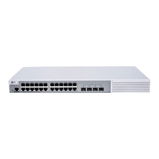
S3910 Series Switches
MANAGED L2+ GIGABIT SWITCHES
MANAGED L2+ GIGABIT SWITCHES
SWITCHS MANAGEABLES L2+ GIGABIT
Quick Start Guide
Quick-Start Anleitung
Guide de Démarrage Rapide
7
8
9
10
11
12
13
14
15
16
17
18
19
20
21
22
23
On =Li nk
Fla shi ng= AC
T
10
11
12
13
14
15
16
17
18
19
20
21
22
23
24
25
V2.0
S3 91 0-2 4T
S
24
S39 10- 24T F
25
SFP
26
27
28
26
27
28
29
30
31
32
33
34
35
36
37
38
39
40
41
42
43
44
45
46
47
48
SFP +
49
50
51
52
S3 91 0- 48
TS
Publicité
Table des Matières

Manuels Connexes pour FS S3910 Serie


Sommaire des Matières pour FS S3910 Serie
- Page 1 S3 91 0-2 4T STA TUS RES ET S39 10- 24T F CON SOL E Gre en= 100 0M Yel low =10 /10 On =Li nk Fla shi ng= AC STA TUS PWR 1 PWR 2 RES ET CON SOL E Gre en= 100 0M Yel low =10 /10 0M On =Li nk...
-
Page 2: Accessories
Introduction Thank you for choosing S3910 Series Stackable Managed Switches. This guide is designed to familiarize you with the layout of the switch and describes how to deploy the switch in your network. S3910-24TF S3910-24TF STATUS RESET CONSOLE Green=1000M Yellow=10/100M On=Link Flashing=ACT S3910-24TS... -
Page 3: Hardware Overview
S3910-24TS/S3910-48TS Power Cord x2 Grounding Cable x1 Rubber Pad x4 Mounting Bracket x2 M4 Screw x8 NOTE: S3910 series switches have dust plugs delivered with them. Keep the dust plugs properly and use them to protect idle optical ports. Hardware Overview Front Panel Ports S3910-24TF S3910-24TF... - Page 4 S3910-24TS S3910-24TS STATUS PWR1 PWR2 SFP+ RESET CONSOLE Green=1000M Yellow=10/100M On=Link Flashing=ACT CONSOLE RJ45 SFP+ S3910-48TS SFP+ STATUS PWR1 PWR2 RESET CONSOLE S3910-48TS Green=1000M Yellow=10/100M On=Link Flashing=ACT CONSOLE RJ45 SFP+ Ports Description RJ45 10/100/1000BASE-T ports for Ethernet connection SFP+ SFP+ ports for 1/10G connection CONSOLE An RJ45 console port for serial management Front Panel Button...
-
Page 5: Front Panel Leds
Back Panels S3910-24TF Cable Clamps Holes Grounding Point Power Supply S3910-24TS/S3910-48TS PWR2 PWR1 Dual Power Supplies Grounding Point Front Panel LEDs S3910-24TF STATUS RJ45 S3910-24TF STATUS RESET CONSOLE Green=1000M Yellow=10/100M On=Link Flashing=ACT LEDs Status Description Off Switch is not receiving power. Blinking Green System is being initialized. - Page 6 LEDs Status Description Off The port is not connected. Solid Green The port is connected at 1000 Mbps. RJ45 Solid Yellow The port is connected at 10/100 Mbps. Blinking Green The port is receiving or transmitting traffic at 1000 Mbps. Blinking Yellow The port is receiving or transmitting traffic at 10/100 Mbps.
- Page 7 LEDs Status Description Off Switch is not receiving power. Blinking Green System is being initialized. Solid Green Switch is operational. Moderate temperature warning: STATUS Solid Yellow Check the working environment of the switch immediately. 1. Severe temperature warning: The temperature severely exceeds the temperature limit, so Solid Red the system is going to restart.
-
Page 8: Installation Requirements
Installation Requirements Before you begin the installation, make sure that you have the followings: Phillips screwdriver. Standard-sized, 19" wide rack with a minimum of 1U height available. Category 5e or higher RJ-45 Ethernet cables, fiber optical cables and console cable for connecting network devices. -
Page 9: Mounting The Switch
Mounting the Switch ST AT US PW R1 PW R2 Desk Mounting RE SE T CO N SO LE G re en = 10 00 M Ye llo w = 10 /1 00 M O n = Li n k Fl as h in g = A C T 1. -
Page 10: Wall Mounting
SF P+ S 3 9 1 0 -4 8 2. Attach the switch to the rack using four M6 screws and cage nuts. Wall Mounting SF P+ S 3 9 1 0 -4 8 S3 91 0- 48 1. Attach the mounting brackets to the switch with the supplied M4 screws. - Page 11 2. Use the expansion screws to securely attach the mounting brackets on the wall. NOTE: Suitable for mounting on concrete or other non-combustible surface only.
- Page 12 Installing the Power Supply Module S3910-48TS/S3910-24TS P W R 1 P W R 2 1. Take a new power module out of the package. 2. Take the plane printed with power information as the top panel of the power module. Hold the handle of the power module with one hand, and hold the end of the power module with the other hand.
-
Page 13: Connecting The Power
Grounding the Switch 1. Connect one end of the grounding cable to a proper earth ground, such as the rack in which the switch is mounted. 2. Secure the grounding lug to the grounding point on the switch back panel with the washers and screws. - Page 14 Connecting the RJ45 Ports S3 90 0- 24 T4 S 1. Connect an Ethernet cable to the RJ45 port of a computer, printer, network storage, or other network devices. 2. Connect the other end of the Ethernet cable to the RJ45 port of the switch. Connecting the SFP/SFP+ Ports SF P+ S 3 9 1 0 -4 8...
- Page 15 Connecting the Console Port STA TU S PW R1 PW R2 RE SE T CO NS OL E Gr ee n= 10 00 M Ye llo w= 10 /1 00 M On =L ink Fla sh ing =A CT 1. Insert the RJ45 connector into the RJ45 console port on the front of the switch. 2.
- Page 16 Stacking the Switches The S3910 series switches support stacking up to 4 units. Switches in the series can be physically stacked using optical fiber cables connected to SFP/SFP+ transceivers or 1/10G Direct Attach Cables (DAC). SFP+ STATUS PWR1 PWR2 RESET CONSOLE Green=1000M Yellow=10/100M On=Link Flashing=ACT S3910-48TS...
- Page 17 Configuring the Switch Configuring the Switch Using the Web-based Interface Step 1: Connect the computer to the business port of the switch using the network cable. Step 2: Set the IP address of the computer to 192.168.1.x. (“x” is any number from 2 to 254.) I nter n et Pro tocol Versi on 4 ( TCP/IP v4) Prop er ti e s General Yo u c a n g e t I P s e t t i n g s a s s i g n e d a u t o m a t i c a l l y i f y o u r n e t w o r k...
- Page 18 Configuring the Switch Using the Console Port Step 1: Connect a computer to the switch's console port using the console cable. Step 2: Start the terminal simulation software such as HyperTerminal on the computer. Step 3: Set the parameters of the HyperTerminal: 9600 bits per second, 8 data bits, no parity, 1 stop bit and no flow control.
-
Page 19: Product Warranty
Product Warranty FS ensures our customers that any damage or faulty items due to our workmanship, we will offer a free return within 30 Days from the day you receive your goods. This excludes any custom made items or tailored solutions. - Page 20 Einführung Vielen Dank, dass Sie sich für die stapelbaren Managed Switches der Serie S3910 entschieden haben. Diese Anleitung soll Sie mit dem Layout des Switches vertraut machen und beschreibt, wie Sie den Switch in Ihrem Netzwerk einsetzen. S3910-24TF S3910-24TF STATUS RESET CONSOLE Green=1000M...
-
Page 21: Hardware-Übersicht
S3910-24TS/S3910-48TS Netzkabel x2 Erdungskabel x1 Gummipad x4 Montagehalterung x2 M4-Schraube x8 NOTE: Die Switches der Serie S3910 werden mit Staubschutzkappen geliefert. Bewahren Sie die Staubschutzkappen ordnungsgemäß auf und verwenden Sie sie zum Schutz ungenutzter optischer Ports. Hardware-Übersicht Ports an der Vorderseite S3910-24TF S3910-24TF STATUS... -
Page 22: Tasten An Der Vorderseite
S3910-24TS S3910-24TS STATUS PWR1 PWR2 SFP+ RESET CONSOLE Green=1000M Yellow=10/100M On=Link Flashing=ACT CONSOLE RJ45 SFP+ S3910-48TS SFP+ STATUS PWR1 PWR2 RESET CONSOLE S3910-48TS Green=1000M Yellow=10/100M On=Link Flashing=ACT CONSOLE RJ45 SFP+ Ports Beschreibung RJ45 10/100/1000BASE-T Ports für Ethernet-Anschluss SFP+ SFP-Ports für 1G-Verbindungen CONSOLE RJ45-Console-Port für serielle Verwaltung Tasten an der Vorderseite... -
Page 23: Leds An Der Vorderseite
Rückseite S3910-24TF Kabelschellen Löcher Erdungspunkt Stromzufuhr S3910-24TS/S3910-48TS PWR2 PWR1 Duale Stromversorgungen Erdungspunkt LEDs an der Vorderseite S3910-24TF STATUS RJ45 S3910-24TF STATUS RESET CONSOLE Green=1000M Yellow=10/100M On=Link Flashing=ACT LEDs Status Beschreibung Switch wird nicht mit Strom versorgt. Blinkt Grün System wird gerade initialisiert. Grün Switch ist betriebsbereit. - Page 24 LEDs Status Beschreibung Der Port ist nicht angeschlossen. Grün Der Port ist mit 1000 Mbit/s verbunden. RJ45 Gelb Der Port ist mit 10/100 Mbit/s verbunden. Blinkt Grün Der Port empfängt oder sendet Datenverkehr mit 1000 Mbit/s. Blinkt Gelb Der Port empfängt oder sendet Datenverkehr mit 10/100 Mbit/s. Der Port ist nicht verbunden.
- Page 25 LEDs Status Beschreibung Switch wird nicht mit Strom versorgt. Blinkt Grün System wird gerade initialisiert. Grün Switch ist betriebsbereit. Warnung vor mäßiger Temperatur: STATUS Gelb Überprüfen Sie sofort die Arbeitsumgebung des Switches. 1. Schwere Temperaturwarnung: Die Temperatur übersteigt den Temperaturgrenzwert erheblich, so dass das System neu gestartet wird.
- Page 26 Installationsvoraussetzungen Bevor Sie mit der Installation beginnen, vergewissern Sie sich, dass Sie über die folgenden Dinge verfügen: Kreuzschlitzschraubendreher. Ein 19"-Rack in Standardgröße mit einer Mindesthöhe von 1HE. RJ-45-Ethernet-Kabel der Kategorie 5e oder höher, Glasfaserkabel und Konsolenkabel für den Anschluss von Netzwerkgeräten. Standortumgebung: Betreiben Sie das Gerät nicht in einem Bereich, in dem die Umgebungstemperatur 50°C übersteigt.
-
Page 27: Montage Des Switches
Montage des Switches ST AT US PW R1 PW R2 Montage auf einem Tisch RE SE T CO N SO LE G re en = 10 00 M Ye llo w = 10 /1 00 M O n = Li n k Fl as h in g = A C T 1. -
Page 28: Wandmontage
SF P+ S 3 9 1 0 -4 8 2. Befestigen Sie den Switch mit vier M6-Schrauben und Käfigmuttern am Rack. Wandmontage SF P+ S 3 9 1 0 -4 8 S3 91 0- 48 1. Befestigen Sie die Montagehalterungen mit den mitgelieferten M4-Schrauben am Switch. - Page 29 2. Verwenden Sie die Spreizschrauben, um die Montagehalterungen sicher an der Wand zu befestigen. HINWEIS: Nur für die Montage auf Beton oder anderen nicht brennbaren Oberflächen geeignet.
- Page 30 Installieren des Stromversorgungsmoduls S3910-48TS/S3910-24TS P W R 1 P W R 2 1. Nehmen Sie ein neues Stromversorgungsmodul aus der Verpackung. 2. Nehmen Sie die mit Strominformationen bedruckte Fläche als Oberseite des Netzteils. Halten Sie den Griff des Leistungsmoduls mit einer Hand fest, und halten Sie das Ende des Leistungsmoduls mit der anderen Hand.
-
Page 31: Anschluss Der Stromversorgung
Erdung des Switches 1. Schließen Sie ein Ende des Erdungskabels an eine geeignete Erdung an, z. B. an das Rack, in dem der Switch montiert ist.switch is mounted. 2. Befestigen Sie die Erdungslasche mit den Unterlegscheiben und Schrauben am Erdungspunkt an der Rückwand des Switches. - Page 32 Anschluss der RJ45-Ports S3 90 0- 24 T4 S 1. Schließen Sie ein Ethernet-Kabel an den RJ45-Port eines Computers, Druckers, Netzwerkspeichers oder anderer Netzwerkgeräte an. 2. Schließen Sie das andere Ende des Ethernet-Kabels an den RJ45-Port des Switches an. Anschluss der SFP/SFP+-Ports SF P+ S 3 9 1 0 -4 8 1.
-
Page 33: Anschließen Des Console-Ports
Anschließen des Console-Ports STA TU S PW R1 PW R2 RE SE T CO NS OL E Gr ee n= 10 00 M Ye llo w= 10 /1 00 M On =L ink Fla sh ing =A CT 1. Stecken Sie den RJ45-Stecker in den RJ45 Console-Port an der Vorderseite des Switches. 2. - Page 34 Stacking der Switches Die Switches der Serie S3910 unterstützen das Stacking von bis zu 4 Einheiten. Die Switches der Serie können mit Glasfaserkabeln, die an SFP/SFP+-Transceiver angeschlossen sind, oder mit 1/10G Direct Attach Kabeln (DAC) physisch gestapelt werden. SFP+ STATUS PWR1 PWR2 RESET CONSOLE Green=1000M Yellow=10/100M On=Link Flashing=ACT...
-
Page 35: Konfiguration Des Switches
Konfiguration des Switches Konfigurieren des Switches über die webbasierte Schnittstelle Schritt 1: Schließen Sie den Computer über das Netzwerkkabel an den Business Port des Switches an. Schritt 2: Stellen Sie die IP-Adresse des Computers auf 192.168.1.x ein. ("x" ist eine beliebige Zahl zwischen 2 und 254.) I nter n et Pro tocol Versi on 4 ( TCP/IP v4) Prop e r ti es General... - Page 36 Konfiguration des Switches mithilfe des Console-Ports Schritt 1: Schließen Sie einen Computer über das Konsolenkabel an den Console-Port des Switches an. Schritt 2: Starten Sie die Terminalsimulationssoftware wie HyperTerminal auf dem Computer. Schritt 3: Stellen Sie die Parameter von HyperTerminal ein: 9600 Bits pro Sekunde, 8 Datenbits, keine Parität, 1 Stoppbit und keine Flow Control.
- Page 37 Kontakt https://www.fs.com/de/contact_us.html Produktgarantie FS garantiert den Kunden, dass wir bei Schäden oder fehlerhaften Artikeln, die auf unsere Verarbeitung zurückzuführen sind, eine kostenlose Rückgabe innerhalb von 30 Tagen nach Erhalt der Ware anbieten. Dies gilt nicht für maßgefertigte Artikel oder maßgeschneiderte Lösungen.
-
Page 38: Accessoires
Introduction Merci d'avoir choisi les Switchs Gérés Empilables de Série S3910. Ce guide est conçu pour que vous puissiez vous familiariser avec la configuration du switch et indique comment procéder à son déploiement. S3910-24TF S3910-24TF STATUS RESET CONSOLE Green=1000M Yellow=10/100M On=Link Flashing=ACT S3910-24TS... -
Page 39: Aperçu Du Matériel
S3910-24TS/S3910-48TS Câble d'Alimentation x2 Câble de Mise à la Terre x1 Coussin en Caoutchouc x4 Support de Montage x2 Vis M4 x8 NOTE: Les switchs de la série S3910 sont livrés avec des capuchons anti-poussière. Conservez correctement ces capuchons et utilisez-les pour protéger les ports optiques inactifs. -
Page 40: Bouton Du Panneau Frontal
S3910-24TS S3910-24TS STATUS PWR1 PWR2 SFP+ RESET CONSOLE Green=1000M Yellow=10/100M On=Link Flashing=ACT CONSOLE RJ45 SFP+ S3910-48TS SFP+ STATUS PWR1 PWR2 RESET CONSOLE S3910-48TS Green=1000M Yellow=10/100M On=Link Flashing=ACT CONSOLE RJ45 SFP+ Ports Description RJ45 Ports 10/100/1000BASE-T pour connexion Ethernet SFP+ Ports SFP+ pour connexion 1/10G CONSOLE Port console RJ45 pour la gestion série Bouton du Panneau Frontal... -
Page 41: Panneau Arrière
Panneau Arrière S3910-24TF Trous de Fixation des Câbles Alimentation Électrique Point de Mise à la Terre S3910-24TS/S3910-48TS PWR2 PWR1 Alimentations Doubles Point de Mise à la Terre LED du Panneau Frontal S3910-24TF STATUS RJ45 S3910-24TF STATUS RESET CONSOLE Green=1000M Yellow=10/100M On=Link Flashing=ACT Indicateurs... - Page 42 Indicateurs Statut Description Éteint Le port n'est pas connecté. Vert Le port est connecté à 1000Mbps. RJ45 Jaune Le port est connecté à 10/100Mbps. Vert Clignotant Le port reçoit ou transmet du trafic à 1000Mbps. Jaune Clignotant Le port reçoit ou transmet du trafic à 10/100Mbps. Éteint Le port n'est pas connecté.
- Page 43 Indicateurs Statut Description Éteint Le switch ne reçoit pas de courant. Vert Clignotant Le système est en cours d'initialisation. Vert Le switch est opérationnel. Avertissement de température modérée : Jaune Vérifiez immédiatement l'environnement opérationnel du STATUS switch. 1.Avertissement de haute température : La température dépasse largement la limite de température, Rouge le système va donc redémarrer.
-
Page 44: Exigences D'installation
Exigences d'Installation Avant de commencer l'installation, assurez-vous que vous disposez des éléments suivants: Tournevis phillips. Rack de taille standard, 19" de large avec hauteur minimum de 1U. Câbles Ethernet RJ-45 de catégorie 5e ou supérieure, câbles à fibre optique et câble de console pour la connexion des périphériques réseau. -
Page 45: Installation Du Switch
Installation du Switch ST AT US PW R1 PW R2 Montage sur Support RE SE T CO N SO LE G re en = 10 00 M Ye llo w = 10 /1 00 M O n = Li n k Fl as h in g = A C T 1. -
Page 46: Montage Mural
SF P+ S 3 9 1 0 -4 8 2. Fixez le switch au rack à l'aide de quatre vis M6 et d'écrous à cage. Montage Mural SF P+ S 3 9 1 0 -4 8 S3 91 0- 48 1. - Page 47 2. Utilisez les vis d'expansion pour fixer solidement les supports de montage sur le mur. NOTE: Adapté uniquement pour un montage sur béton ou autre surface non inflammable.
-
Page 48: Installation Du Module D'alimentation
Installation du Module d'Alimentation S3910-48TS/S3910-24TS P W R 1 P W R 2 1. Retirez le nouveau module d'alimentation de son emballage. 2. Prenez le panneau imprimé avec les informations sur l'alimentation en tant que panneau supérieur du module d'alimentation. Saisissez la poignée du module d'alimentation d'une main, et l'extrémité du module d'alimentation de l'autre main. -
Page 49: Mise À La Terre Du Switch
Mise à la Terre du Switch 1. Connectez une extrémité du câble de mise à la terre à une terre appropriée, telle que le rack dans lequel le switch est monté. 2. Fixez la fiche de mise à la terre au point de mise à la terre sur le panneau arrière du switch à l'aide des rondelles et des vis. -
Page 50: Connexion Des Ports Rj45
Connexion des Ports RJ45 S3 90 0- 24 T4 S 1. Connectez un câble Ethernet au port RJ45 d'un ordinateur, d'une imprimante, d'un stockage réseau ou d'autres périphériques réseau. 2. Connectez l'autre extrémité du câble Ethernet au port RJ45 du switch. Connexion des Ports SFP/SFP+ SF P+ S 3 9 1 0 -4 8... -
Page 51: Connexion Du Port Console
Connexion du Port Console STA TU S PW R1 PW R2 RE SE T CO NS OL E Gr ee n= 10 00 M Ye llo w= 10 /1 00 M On =L ink Fla sh ing =A CT 1. Insérez le connecteur RJ45 dans le port de console RJ45 situé sur la face frontale du switch. 2. - Page 52 Empilage des Switchs Les switchs de la série S3910 supportent l'empilage de 4 unités au maximum. Les switchs peuvent être physiquement empilés à l'aide de câbles en fibre optique connectés à des émetteurs-récepteurs SFP/SFP+ ou à des Câbles à Attache Direct (DAC) 1/10G. SFP+ STATUS PWR1 PWR2 RESET...
-
Page 53: Configuration Du Switch
Configuration du Switch Configuration du Switch à l'Aide de l'Interface Web Étape 1: Connectez l'ordinateur au port du switch à l'aide du câble réseau. Étape 2: Définissez l'adresse IP de l'ordinateur sur 192.168.1.x. ("x" correspond à un nombre quelconque compris entre 2 et 254). I nter n et Pro tocol Versi on 4 ( TCP/IP v4) Prop e r ti es General Yo u c a n g e t I P s e t t i n g s a s s i g n e d a u t o m a t i c a l l y i f y o u r n e t w o r k... -
Page 54: Dépannage
Configuration du Switch à l'Aide du Port Console Étape 1: Connectez un ordinateur au port de console du switch à l'aide du câble de console. Étape 2: Démarrez le logiciel HyperTerminal sur l'ordinateur. Étape 3: Réglez les paramètres de l'HyperTerminal : 9600 bits par seconde, 8 bits de données, pas de parité, 1 bit d'arrêt et pas de contrôle de flux. -
Page 55: Le Port Ne Fonctionne Pas, L'indicateur Led Est Éteint
Garantie du Produit FS garantit à ses clients que tout article endommagé ou défectueux dû à sa fabrication pourra être retourné gratuitement dans un délai de 30 Jours à compter de la date de réception de la marchandise. Cela exclut les articles fabriqués sur mesure ou les solutions personnalisées. -
Page 56: Compliance Information
Any changes or modifications not expressly approved by the grantee of this device could void the user's authority to operate the equipment. Responsible party (only for FCC matter) FS.COM Inc. 380 Centerpoint Blvd, New Castle, DE 19720, United States https://www.fs.com... - Page 57 Die FS.COM GmbH erklärt hiermit, dass dieses Gerät mit der Richtlinie 2014/30/EU und 2014/35/EU konform ist. Eine Kopie der EU-Konformitätserklärung finden Sie unter www.fs.com/de/company/quality_control.html. FS.COM GmbH déclare par la présente que cet appareil est conforme à la Directive 2014/30/UE et 2014/35/UE. Une copie de la Déclaration UE de Conformité est disponible sur https://www.fs.com/fr/company/quality_control.html FS.COM LIMITED...