
Manuels Connexes pour FS S5850-24S2C-DC


Sommaire des Matières pour FS S5850-24S2C-DC
- Page 1 100 G S5850-24S2C-DC/S5850-24S2C MANAGED L3 ROUTING SWITCH MANAGED L3 ROUTING SWITCH SWITCH DE ROUTAGE L3 MANAGEABLE Quick Start Guide V1.0 Quick Start Anleitung Guide de Démarrage Rapide...
- Page 2 Introduction Thank you for choosing S5850-24S2C-DC/S5850-24S2C Switch. This guide is designed to familiarize you with the layout of the switch and describes how to deploy the switch in your network. ID SYS 10 11 14 15 16 17 18 19...
- Page 3 S5850-24S2C: Power cord x1 Console Cable x1 Cat5e Cable x1 Rubber Pad x4 M4 Screw x8 Grounding Cable x1 Mounting Bracket x2...
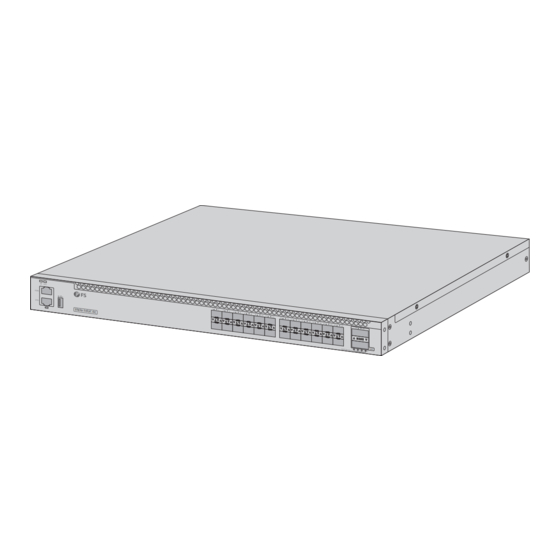
- Page 4 SFP+ QSFP28 ID SYS 10 11 14 15 16 17 18 19 20 21 22 23 S5850-24S2C-DC 100G 40GE Breakout Ports Description SFP+ SFP+ ports for 1/10G connection. QSFP28 QSFP28 ports for 40/100G connection. An RJ45 console port for serial management.
- Page 5 LEDs Status Description Blue ID indication function enable. Off ID indication function disable. Green The System is normally running. Amber The system occurs alarm or error. Off No power or no system runs or runs abnormally. Green Port is linked. Blinking Green Port is receiving or transmitting packets.
- Page 6 Installation Requirements Before you begin the installation, make sure that you have the followings: Phillips screwdriver. M6 Screws. Standard-sized, 19" wide rack with a minimum of 1U height available. Category 5e or higher RJ-45 Ethernet cables, fi ber optical cables, and console cable for ID SY S connecting network devices.
- Page 7 Rack Mounting 14 15 16 17 18 19 20 21 22 23 40 G 10 0G 40 GE Bre ak ou t 1. Secure the mounting brackets to the two sides of the switch with eight M4 screws. 14 15 16 17 18 19 20 21...
- Page 8 Grounding the Switch ID SY S NU LL CO N ET H -4 8V - -6 0V S 5 8 5 0 -2 4 S 2 Q 1. Connect one end of the grounding cable to a proper earth ground, such as the rack in which the switch is mounted.
- Page 9 Name Description Positive Negative ID SY S CO N NULL Null ET H S 5 8 5 0 -2 4 S 2 Q 2. Tighten the wire-clamp screws to prevent the wires from loosening. Connecting the SFP+ Ports 14 15 16 17 18 19 20 21...
- Page 10 Connecting the QSFP28 Ports 14 15 16 17 18 19 20 21 22 23 10 0G 40 GE Br ea ko ut First install QSFP28 transceivers and then connect the fiber optic cable to the transceiver ports, or connect DAC cables to the QSFP28 slots. Connecting the Management Ports Connecting the Console Port ID SY S...
- Page 11 Connecting the ETH Port ID SY S CO N ET H 1. Connect one end of a standard RJ45 Ethernet cable to a computer. 2. Connect the other end of the cable to the ETH port on the front of the switch. Connecting the USB Port ID SY S CO N...
- Page 12 Configuring the Switch Configuring the Switch via the Web-based Interface Step 1: Connect the computer to the Management port of the switch with the network cable. Step 2: Set the IP address of the computer to 192.168.1.x. (“x” is any number from 2 to 254.) Set the subnet mask of the computer to 255.255.255.0.
- Page 13 Configuring the Switch Using the Console Port Step 1: Connect a computer to the switch's console port using the supplied console cable. Step 2: Start the terminal simulation software such as HyperTerminal on the computer. Step 3: Set the parameters of the HyperTerminal: 115200 bits per second, 8 data bits, no parity, 1 stop bit and no flow control.
- Page 14 Troubleshooting Loading Failure Troubleshooting After loading fails, the system will keep running in the original version. At this time, users should re-check if physical port connections are good firstly. If some ports are not connected, then re-connect them to ensure that physical connections are correct, and begin re-loading. If physical connections are correct, then check the loading process information displayed on the super terminal to verify if there are input errors.
- Page 15 Product Warranty FS ensures our customers that if there are any damage or faulty items due to our workmanship, we will offer a free return within 1 month from the day you receive your goods. This excludes any custom made items or tailored solutions.
- Page 16 Einführung Vielen Dank, dass Sie sich für den S5850-24S2C-DC/S5850-24S2C Switch entschieden haben. Dieses Handbuch soll Sie mit dem Aufbau des Switches vertraut machen und beschreibt, wie Sie den Switch in Ihrem Netzwerk einsetzen. ID SYS 10 11 14 15 16 17...
- Page 17 S5850-24S2C: 1x Netzkabel 1x Konsolenkabel 1x Cat5e-Kabel 4x Gummipad 8x M4-Schraube 1x Erdungskabel 2x Montagehalterung...
- Page 18 Ports an der Vorderseite SFP+ QSFP28 ID SYS 10 11 14 15 16 17 18 19 20 21 22 23 S5850-24S2C-DC 100G 40GE Breakout Ports Beschreibung SFP+ SFP+-Ports für 1/10G Verbindungen. QSFP28 QSFP28-Ports für 40/100G Verbindungen. Ein RJ45-Konsolenport für serielle Verwaltung.
- Page 19 LEDs Status Beschreibung Blau ID-Anzeigefunktion aktivieren. ID-Anzeigefunktion deaktivieren. Grün Das System funktioniert normal. Bernstein Das System zeigt einen Alarm oder Fehler an. Kein Strom oder kein System läuft oder läuft fehlerhaft. Grün Port ist verbunden. Blinkt Grün Der Port empfängt oder sendet Pakete. Port ist nicht verbunden.
- Page 20 Installationsanforderungen Bevor Sie mit der Installation beginnen, vergewissern Sie sich, dass Sie über die folgenden Dinge verfügen: Kreuzschlitzschraubendreher. M6 Schrauben. Ein 19"-Rack in Standardgröße mit einer Mindesthöhe von 1 HE. ID SY S RJ-45-Ethernet-Kabel der Kategorie 5e oder höher, Glasfaserkabel und Konsolenkabel für den CO N ET H Anschluss von Netzwerkgeräten.
- Page 21 Rack-Montage 14 15 16 17 18 19 20 21 22 23 40 G 10 0G 40 GE Bre ak ou t 1. Befestigen Sie die Montagehalterungen mit acht M4-Schrauben an den beiden Seiten des Switches. 14 15 16 17 18 19 20 21 22 23 1 0 0 G...
- Page 22 Erdung des Switches ID SY S NU LL CO N ET H -4 8V - -6 0V S 5 8 5 0 -2 4 S 2 Q 1. Schließen Sie ein Ende des Erdungskabels an eine geeignete Erdung an, z. B. an das Rack, in dem der Switch montiert ist.
- Page 23 Name Beschreibung Positiv Negativ ID SY S CO N NULL Null ET H S 5 8 5 0 -2 4 S 2 Q 2. Ziehen Sie die Schrauben der Drahtklemmen fest, damit sich die Drähte nicht lockern können. Anschließen der SFP+-Ports 14 15 16 17 18 19...
- Page 24 Anschließen der QSFP28-Ports 14 15 16 17 18 19 20 21 22 23 10 0G 40 GE Br ea ko ut Installieren Sie zunächst QSFP28-Transceiver und schließen Sie dann das Glasfaserkabel an die Transceiver-Ports an, oder schließen Sie DAC-Kabel an die QSFP28-Steckplätze an. Anschließen der Management-Ports Anschließen des Konsolenports ID SY S...
- Page 25 Anschließen des ETH-Ports ID SY S CO N ET H 1. Schließen Sie ein Ende eines Standard-RJ45-Ethernetkabels an einen Computer an. 2. Schließen Sie das andere Ende des Kabels an den ETH-Port an der Vorderseite des Switches an. Anschließen des USB-Ports ID SY S CO N ET H...
- Page 26 Konfigurieren des Switches Konfigurieren des Switches über die webbasierte Schnittstelle Schritt 1: Schließen Sie den Computer mit dem Netzwerkkabel an den Verwaltungsport des Switches an. Schritt 2: Stellen Sie die IP-Adresse des Computers auf 192.168.1.x ein. ("x" ist eine beliebige Zahl von 2 bis 254.) Setzen Sie die Subnetzmaske des Computers auf 255.255.255.0.
- Page 27 Konfigurieren des Switches über den Konsolenports Schritt 1: Schließen Sie einen Computer über das mitgelieferte Konsolenkabel an den Konsolenport des Switches an. Schritt 2: Starten Sie die Terminalsimulationssoftware, z. B. HyperTerminal, auf dem Computer. Schritt 3: Stellen Sie die Parameter von HyperTerminal ein: 115200 Bits pro Sekunde, 8 Datenbits, keine Parität, 1 Stoppbit und keine Flusskontrolle.
- Page 28 Fehlersuche Fehlerbehebung bei Ladefehlern Wenn das Laden fehlschlägt, läuft das System in der ursprünglichen Version weiter. Zu diesem Zeitpunkt sollten die Benutzer zunächst überprüfen, ob die physischen Portverbindungen in Ordnung sind. Wenn einige Ports nicht angeschlossen sind, schließen Sie sie erneut an, um sicherzustellen, dass die physikalischen Verbindungen korrekt sind, und beginnen Sie mit dem erneuten Laden.
- Page 29 Produkt-Garantie FS garantiert seinen Kunden, dass wir im Falle von Schäden oder fehlerhaften Artikeln, die auf unsere Verarbeitung zurückzuführen sind, eine kostenlose Rücksendung innerhalb von 1 Monat ab dem Tag, an dem Sie Ihre Ware erhalten haben, anbieten. Dies gilt nicht für maßgefertigte Artikel oder maßgeschneiderte Lösungen.
- Page 30 Introduction Merci d'avoir choisi le switch S5850-24S2C-DC/S5850-24S2C. Ce guide est conçu que vous puissiez vous familiariser avec la configuration du switch et vous indiquer comment procéder à son déploiement. ID SYS 10 11 14 15 16 17 18 19 20 21...
- Page 31 S5850-24S2C : Cordon d'alimentation x2 Câble de Console x1 Câble Cat5e x1 Coussin en Caoutchouc x4 Vis M4 x8 Câble de Mise à la Terre x1 Support de Montage x2...
- Page 32 SFP+ QSFP28 ID SYS 10 11 14 15 16 17 18 19 20 21 22 23 S5850-24S2C-DC 100G 40GE Breakout Ports Description SFP+ Ports SFP+ pour modules 1/10G. QSFP28 Ports QSFP28 pour connexion 40/100G. Port console RJ45 pour la gestion série.
- Page 33 Indicateur Statut Description Bleu Activation de la fonction d'indication de l'ID. Éteint Désactivation de la fonction d'indication de l'ID. Vert Le système fonctionne normalement. Amber Le système présente une alarme ou une erreur. L'alimentation est coupée ou le système ne fonctionne Éteint pas ou fonctionne anormalement.
- Page 34 Exigences d'Installation Avant de commencer l'installation, assurez-vous que vous disposez des éléments suivants : Tournevis phillips. Vis M6. Rack de taille standard, 19" de large, avec une hauteur minimum de 1U. ID SY S Câbles Ethernet RJ-45 de catégorie 5e ou supérieure, câbles optiques et câble de console pour la CO N connexion des périphériques réseau.
- Page 35 Montage sur Rack 14 15 16 17 18 19 20 21 22 23 40 GE Bre 40 G 10 0G ak ou t 1. Fixez les supports de montage aux deux côtés du switch à l'aide de huit vis M4. 14 15 16 17 18 19...
- Page 36 Mise à la Terre du Switch ID SY S NU LL CO N ET H -4 8V - -6 0V S 5 8 5 0 -2 4 S 2 Q 1. Connectez une extrémité du câble de mise à la terre à une mise à la terre appropriée, telle que le rack dans lequel le switch est monté.
- Page 37 N° Description Positif Négatif ID SY S CO N ET H S 5 8 5 0 -2 4 S 2 Q 2. Serrez les vis de fixation des fils pour éviter qu'ils ne se détachent. Connexion des Ports SFP+ 14 15 16 17 18 19 20 21...
- Page 38 Connexion des Ports QSFP28 14 15 16 17 18 19 20 21 22 23 10 0G 40 GE Br ea ko ut Installez d'abord les modules QSFP28, puis connectez le câblage en fibre optique aux ports des modules, ou connectez les câbles DAC aux emplacements QSFP28. Connexion des Ports de Gestion Connexion du Port Console ID SY S...
- Page 39 Connexion au Port ETH ID SY S CO N ET H 1. Connectez une extrémité d'un câble Ethernet standard RJ45 à un ordinateur. 2. Connectez l'autre extrémité du câble au port ETH situé sur la face frontale du switch. Connexion au Port USB ID SY S CO N ET H...
- Page 40 Configuration du Switch Configuration du Switch à l'Aide de l'Interface Web Étape 1 : Connectez l'ordinateur au port de gestion du switch à l'aide du câble réseau. Étape 2 : Définissez l'adresse IP de l'ordinateur sur 192.168.1.x. ("x" est un nombre quelconque compris entre 2 et 254).
- Page 41 Configuration du Switch à l'Aide du Port Console Étape 1 : Connectez un ordinateur au port de console du switch à l'aide du câble de console fourni. Étape 2 : Démarrez le logiciel HyperTerminal sur l'ordinateur. Étape 3 : Définissez les paramètres de l'HyperTerminal : 115200 bits par seconde, 8 bits de données, pas de parité, 1 bit d'arrêt et pas de contrôle de flux.
- Page 42 Dépannage Dépannage en Cas d'Échec du Chargement Après l'échec du chargement, le système fonctionnera dans sa version originale. À ce moment-là, il est conseillé de revérifier d'abord si les connexions des ports physiques sont bien établies. Si certains ports ne sont pas connectés correctement, reconnectez-les pour vous assurer que les connexions physiques sont bien établies, puis commencez à...
- Page 43 Garantie du Produit FS garantit à ses clients que tout article endommagé ou défectueux dû à sa fabrication pourra être retourné gratuitement dans un délai de 1 mois à compter de la date de réception de la marchandise, à l'exception des articles fabriqués sur mesure ou des solutions personnalisées.