Table des Matières
Publicité
Les langues disponibles
Les langues disponibles
Liens rapides
Leggere attentamente le istruzioni prima di installare e utilizzare l'apparecchiatura.
Read the instructions carefully before installing and using the appliance.
Vor der Installation und Nutzung des Geräts müssen die Anleitungen aufmerksam durchgelesen werden.
Lire attentivement les instructions avant d'installer et d'utiliser l'appareil.
Léanse atentamente las instrucciones antes de instalar y utilizar el aparato.
Il mancato rispetto delle istruzioni fa decadere la garanzia del fabbricante.
In the event of failure to comply with the instructions, the manufacturer's warranty shall cease to apply.
Die Missachtung der Anleitungen hat den Verfall der vom Hersteller gewährten Garantie zur Folge.
Le non respect des instructions entraîne l'invalidation de la garantie du fabricant.
La inobservancia de las instrucciones provoca la invalidación de la garantía otorgada por el fabricante.
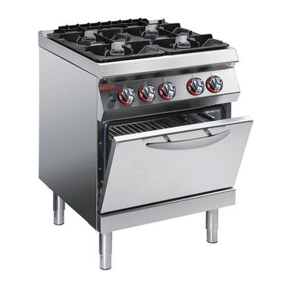
CUCINA FUOCHI APERTI + FORNO
GASHERD MIT OFFENEN FLAMMEN + BACKOFEN
COCINA FUEGOS ABIERTOS + HORNO
OPEN BURNER RANGE + OVEN
CUISINIÈRE FEUX VIFS + FOUR
MANUALE D'USO E INSTALLAZIONE
BEDIEN- UND INSTALLATIONSHANDBUCH
MANUEL D'UTILISATION ET D'INSTALLATION
USE AND INSTALLATION MANUAL
MANUAL DE USO E INSTALACIÓN
1G1FA0E
1G1FA0EV
2G1FA0EV
Italiano
English
Deutsch
Français
Español
Rev. 0
05/2019
3142902
IT
GB
DE
FR
ES
Publicité
Chapitres
Table des Matières

Manuels Connexes pour Angelo Po 1G1FA0E


Sommaire des Matières pour Angelo Po 1G1FA0E
- Page 1 Le non respect des instructions entraîne l'invalidation de la garantie du fabricant. La inobservancia de las instrucciones provoca la invalidación de la garantía otorgada por el fabricante. CUCINA FUOCHI APERTI + FORNO OPEN BURNER RANGE + OVEN 1G1FA0E GASHERD MIT OFFENEN FLAMMEN + BACKOFEN 1G1FA0EV CUISINIÈRE FEUX VIFS + FOUR...
- Page 2 Cautela - Avvertenza Importante Non usare prodotti che contengono sostanze Verificare quotidianamente che i dispositivi dannose e pericolose per la salute delle per- di sicurezza siano perfettamente installati sone (solventi, benzine, ecc.). ed efficienti. Importante Cautela - Avvertenza La pavimentazione, in prossimità dell’appa- L’allacciamento deve essere eff ettuato da recchiatura potrebbe essere scivolosa.
-
Page 3: Table Des Matières
INDICE rif. capitoli pag. 1 INFORMAZIONI GENERALI ..........3 2 INFORMAZIONI TECNICHE ..........5 3 SICUREZZA............... 7 PARTE 4 USO E FUNZIONAMENTO ..........9 5 MANUTENZIONI .............. 12 6 GUASTI ................14 7 MOVIMENTAZIONE E INSTALLAZIONE ......16 8 REGOLAZIONI ..............21 PARTE 9 SOSTITUZIONE PARTI ........... - Page 4 to gas (bruciatori di piano), 21 Sicurezza, dispositivi di, 6 Spia pilota bruciatore di piano, sosti- Regolazioni, raccomandazioni per Sicurezza, norme per la, 7 tuzione ugello, 24 le, 21 Sollevamento e movimentazione, 16 Trasformazione alimentazione, 19 Ricerca guasti, 14 Sostituzione ugello bruciatore di pia- Trasporto, 16 Ripristino apparecchiatura, 11 no, 23...
-
Page 5: Informazioni Generali
INFORMAZIONI GENERALI ISTRUZIONI E AVVERTENZE PER IL LETTORE Per rintracciare facilmente gli argomenti specifici di parte: contiene tutte le informazioni ne- interesse, consultare l’indice analitico posto all’ini- cessarie ai destinatari omogenei, cioè tutti gli zio del manuale. operatori esperti e autorizzati a movimentare, Questo manuale è... -
Page 6: Identificazione Fabbricante E Apparecchiatura
) Potenza dichiarata (kW) IDM-39614900100.tif MODALITÀ DI RICHIESTA ASSISTENZA Per qualsiasi esigenza rivolgersi alle agenzie o alla sede centrale Angelo Po i cui riferimenti sono ripor- tati nella sezione contatti del sito internet http:// www.angelopo.com. Per ogni richiesta di assistenza tecnica, indicare i dati riportati sulla targhetta di identificazione ed il tipo di difetto riscontrato. -
Page 7: Informazioni Tecniche
INFORMAZIONI TECNICHE DESCRIZIONE GENERALE APPARECCHIATURA La cucina fuochi aperti con forno, d'ora innanzi de- finita apparecchiatura, è stata progettata e costruita per la preparazione e cottura di alimenti nell'ambito della ristorazione professionale. In funzione delle esigenze di utilizzo, l'apparecchia- 6 kW tura è... -
Page 8: Dati Tecnici
DATI TECNICI Vedi tabelle e “Scheda allacciamenti” in fondo al manuale. DISPOSITIVI DI SICUREZZA Anche se l’apparecchiatura è completa di tutti i di- spositivi di sicurezza, in fase di installazione e allac- ciamento essi dovranno, se necessario, essere integrati con altri in modo da rispettare le leggi vi- genti in materia. -
Page 9: Accessori A Richiesta
ACCESSORI A RICHIESTA A richiesta l'apparecchiatura può essere corredata dei seguenti accessori (vedi “catalogo generale”). SICUREZZA ISTRUZIONI E AVVERTENZE PER LA SICUREZZA Il fabbricante, in fase di progettazione e costruzio- nanze e danni economici. ne, ha posto particolare attenzione agli aspetti che Tutti gli interventi di manutenzione che richiedono possono provocare rischi alla sicurezza e alla salu- una precisa competenza tecnica o particolari capa-... -
Page 10: Istruzioni E Avvertenze Di Sicurezza Per L'impatto Ambientale
Durante il lavaggio dell'apparecchiatura non dirige- Importante re getti d'acqua in pressione sulle parti interne dell'apparecchiatura. I collegamenti necessari (acqua, elettricità e gas) devono essere eff ettuati esclusiva- Non lasciare oggetti o materiale infiammabile in mente da personale adeguatamente specia- prossimità... -
Page 11: Uso E Funzionamento
USO E FUNZIONAMENTO ISTRUZIONI E AVVERTENZE PER L’USO E IL FUNZIONAMENTO Importante Gli utilizzatori, oltre ad essere autorizzati ed Prima dell’uso verificare che i dispositivi di si- opportunamente documentati, formati ed ad- curezza siano perfettamente installati ed effi- destrati, se necessario, al primo uso, dovran- cienti. - Page 12 ACCENSIONE E SPEGNIMENTO BRUCIATORI DI PIANO Accensione 1 - Aprire il rubinetto alimentazione gas. 2 - Premere e ruotare la manopola (A) in senso an- tiorario (pos. 1) ed accendere la spia pilota. 3 - Mantenere premuta la manopola per circa 15 sec per consentire l'intervento della termocoppia.
-
Page 13: Inattività Prolungata Dell'apparecchiatura
2 - Ruotare la manopola (B) in posizione 1, fra la Spegnimento temperatura minima e massima e attendere il 4 - Ruotare la manopola (B) in posizione 3 per di- tempo di preriscaldamento prima di utilizzare il sattivare le resistenze di riscaldamento. forno. -
Page 14: Istruzioni Ed Avvertenze Per L'uso
ISTRUZIONI ED AVVERTENZE PER L’USO Al fine di garantire un corretto uso dell'apparecchia- – Utilizzare, per la cottura nel forno, le guide supe- tura, è bene applicare i seguenti consigli. riori per le torte e le guide inferiori per gli arrosti. –... -
Page 15: Pulizia Apparecchiatura
PULIZIA APPARECCHIATURA Se si considera che l'apparecchiatura è utilizzata per 3 - Pulire gli accessori dopo l’uso, con uno sgras- la preparazione di prodotti alimentari per l'uomo, è ne- sante idoneo. Si consiglia il lavaggio in lavasto- cessario prestare particolare cura a tutto ciò che ri- viglie. -
Page 16: Pulizia Forno
Per qualsiasi esigenza rivolgersi alle agen- Alcuni di questi problemi possono essere risolti zie o alla sede centrale Angelo Po i cui rife- dall’utilizzatore, per tutti gli altri è richiesta una pre- rimenti sono riportati nella sezione contatti del sito internet http://www.angelopo.com. - Page 17 Inconvenienti Cause Rimedi Chiudere il rubinetto Fuga occasionale dovuta a Odore di gas. alimentazione gas e aerare il spegnimento fiamma. locale. Verificare l’efficienza dei dispositivi di accensione. Accendere manualmente con fiamma libera. I dispositivi di accensione a scintilla non funzionano. La spia pilota non si accende.
-
Page 18: Movimentazione E Installazione
MOVIMENTAZIONE E INSTALLAZIONE ISTRUZIONI E AVVERTENZE PER LA MOVIMENTAZIONE E INSTALLAZIONE Importante Tutte le operazioni di movimentazione e di torizzato ad eseguire queste operazioni installazione dovranno essere eseguite nel dovrà, se necessario, organizzare un "pia- rispetto della legislazione vigente in mate- no di sicurezza"... -
Page 19: Installazione Apparecchiatura
INSTALLAZIONE APPARECCHIATURA Tutte le fasi di installazione devono essere conside- rate sin dalla realizzazione del progetto generale. Prima di iniziare tali fasi, oltre alla definizione della zona di installazione, chi è autorizzato ad eseguire queste operazioni dovrà, se necessario, attuare un “piano di sicurezza”... - Page 20 LIVELLAMENTO Agire sui piedi di appoggio (A) per livellare l'appa- recchiatura. IDM-39614401600.tif MONTAGGIO APPARECCHIATURE IN BATTERIA Per montare le apparecchiature in batteria (fianco a fianco) procedere nel modo indicato. 1 - Sfilare le manopole (A). 2 - Svitare le viti (C) e smontare i cruscotti (B). 3 - Applicare, sui bordi da accostare, del nastro adesivo di protezione.
-
Page 21: Allacciamento Gas
ALLACCIAMENTO GAS Importante Chi è autorizzato ad effettuare tale operazio- ne deve possedere capacità ed esperienza acquisita e riconosciuta nel settore specifico, dovrà eseguire l'allacciamento a regola d'arte e tenere conto di tutti i requisiti normativi e le- gislativi. Ad allacciamento completato, prima di rendere operativa l'attrezzatura, si dovrà... -
Page 22: Allacciamento Elettrico
L'apparecchiatura viene fornita con ten- personale autorizzato e qualificato, nel ris- sione di funzionamento a 230V/1N (solo per petto delle leggi vigenti in materia e con l'uti- versione 1G1FA0E). lizzo di materiale appropriato e prescritto. L'apparecchiatura viene fornita con ten- sione... -
Page 23: Collaudo Apparecchiatura
COLLAUDO APPARECCHIATURA (vedi pag. 19). Importante 5 - Verificare la regolare accensione e combustio- Prima della messa in servizio, deve essere ne dei bruciatori di piano. eseguito il collaudo dell'impianto, al fine di 6 - Verificare e, se necessario, regolare la pressio- valutare le condizioni operative di ogni sin- ne e la portata del gas al minimo e al massimo golo componente ed individuare le even-... - Page 24 Per questa operazione procedere nel modo indicato. 6 - Dopo la regolazione sigillare la vite con vernice. 1 - Chiudere il rubinetto alimentazione gas 7 - Rimontare il cruscotto (B) e le manopole (A) ad 2 - Sfilare le manopole (A). operazione ultimata.
-
Page 25: Ingrassaggio Rubinetto Gas
INGRASSAGGIO RUBINETTO GAS Per questa operazione procedere nel modo indicato. 7 - Cospargere di grasso il cono (F), inserirlo nella 1 - Chiudere il rubinetto alimentazione gas. sua sede e ruotarlo alcune volte. 2 - Sfilare le manopole (A). 8 - Sfilare il cono (F) per eliminare il grasso in ec- 3 - Svitare le viti (C) e smontare il cruscotto (B). -
Page 26: Sostituzione Ugello Spia Pilota Bruciatore Di Piano
SOSTITUZIONE UGELLO SPIA PILOTA BRUCIATORE DI PIANO Per questa operazione procedere nel modo indicato. 5 - Estrarre l'ugello (E) e sostituirlo con quello 1 - Chiudere il rubinetto alimentazione gas. adatto al tipo di gas utilizzato (vedi tabella in 2 - Sfilare le manopole (A). fondo al manuale). - Page 28 Caution - warning Important Never use products containing substances Make a daily check that the safety devices harmful or hazardous for health (solvents, are properly installed and in good working petroleum spirits, etc.). order. Important Caution - warning The floor, near the appliance, could be slippe- The connection must be made by authori- sed, skilled personnel, in accordance with the relevant legal requirements, using ap-...
- Page 29 CONTENTS ref. chapters page 1 GENERAL INFORMATION ..........3 2 TECHNICAL INFORMATION..........5 3 SAFETY ................7 PART 4 USE AND OPERATION ............. 9 5 SERVICING ..............12 6 FAULT ................14 7 HANDLING AND INSTALLATION ........16 8 ADJUSTMENTS............... 21 PART 9 REPLACING PARTS ............
- Page 30 Switching the top burner on Top burner pilot light, nozzle Top burner, switching on and off, 10 and off, 10 replacement, 23 Transport, 15 Top burner, replacing pilot light Troubleshooting, 14 Technical data, 5 nozzle, 23 Testing of the appliance, 19 Unpacking and packaging, 15 - 2 - English...
-
Page 31: General Information
GENERAL INFORMATION INSTRUCTIONS AND WARNINGS FOR THE READER To find the specific topics of interest to you quickly, part: contains all the information neces- refer to the index at the start of the manual. sary for special categories of reader, i.e. all This manual is subdivided into two parts. -
Page 32: Identification Of Manufacturer And Appliance
IDM-39614900100.tif PROCEDURE FOR REQUESTING SERVICE For all requirements contact the agents or the head- quarters of Angelo Po which can be found in the contacts section of the website http:// www.angelo- po.com. When requesting service, state the data provide on the nameplate and provide a description of the fault. -
Page 33: Technical Information
TECHNICAL INFORMATION GENERAL DESCRIPTION OF APPLIANCE The open burner range with oven, referred to from now on as the appliance, is designed and construct- ed for preparing and cooking foods in the profes- sional catering sector. The appliance is produced in several versions to 6 kW meet varying user requirements (see diagram). -
Page 34: Technical Data
TECHNICAL DATA See tables and "Connection chart" at the back of the manual. SAFETY DEVICES Although the appliance is complete with all safety devices, during installation and connection addi- tional devices must be added if necessary to com- ply with the relevant legal requirements. The illustration shows the position of the devices. -
Page 35: Optional Accessories
OPTIONAL ACCESSORIES The appliance can be equipped with the following accessories on request (“see general catalogue”). SAFETY INSTRUCTIONS AND WARNINGS FOR SAFETY During design and construction, the manufacturer recognised experienced gained in the specific field has paid special attention to factors which may of intervention. -
Page 36: Safety Warnings And Instructions Concerning Environmental Impact
Important The necessary connections (water, electri- city and gas) must be set up exclusively by suitably specialised staff , in accordance with local requirements. SAFETY WARNINGS AND INSTRUCTIONS CONCERNING ENVIRONMENTAL IMPACT Every organisation is obliged to apply procedures to The Safe Disposal of Waste from Electrical and identify and monitor the effects of its operations Electronic Equipment (WEEE Directive 2002/96/ (products, services, etc.) on the environment. -
Page 37: Use And Operation
USE AND OPERATION INSTRUCTIONS AND WARNINGS FOR USE AND OPERATION Important Besides being authorised and appropriate- Before use, check that the safety devices ly documented,and if necessary,instructed are properly installed and in good working and trained, users,on fi rst usage, have to order. -
Page 38: Switching The Oven On And Off
SWITCHING THE TOP BURNER ON AND OFF Lighting 1 - Turn on the gas supply tap. 2 - Press the knob (A) and turn it anti-clockwise (pos. 1) to light the pilot light. 3 - Keep the knob pressed for about 15 sec. to prime the thermocouple. -
Page 39: Resetting The Appliance
2 - Turn the knob (B) to setting 1, between the mi- Turning off nimum and maximum temperature, and wait for 4 - Turn the knob (B) to setting 3, to switch off the the warm-up time before using the oven.The li- heating elements. -
Page 40: Instructions And Warnings For Use
INSTRUCTIONS AND WARNINGS FOR USE To ensure correct use of the appliance, the follow- – When cooking in the oven, use the top guides for ing rules should be adopted. cakes and the bottom guides for roasts. – Use only the accessories recommended by the –... -
Page 41: Cleaning Instructions
CLEANING INSTRUCTIONS Since the appliance is used for preparing foods for 3 - After use, clean the accessories with a suitable human consumption, special care must be paid to grease-remover product. If possible, wash in everything relating to hygiene, and the appliance the dishwasher. -
Page 42: Fault
For all requirements contact the agents or the headquarters of Angelo Po which can use. The user can solve some of these problems be found in the contacts section of the web- himself, but for others specific technical knowledge site http://www.angelopo.com. - Page 43 Faults Causes Remedies Occasional leak because flame Turn off the gas supply tap and Smell of gas has gone out ventilate the room Check that the ignition devices are in good working order Light by hand with a naked light The spark ignition devices are not working Important...
-
Page 44: Handling And Installation
HANDLING AND INSTALLATION INSTRUCTIONS AND WARNINGS FOR FOR HANDLING AND INSTALLATION Important All handling and installation operations If necessary, the person authorised to car- should be carried out in accordance with ry out these operations must organise a current legislation on health and safety at "safety plan"... -
Page 45: Installation Of The Appliance
INSTALLATION OF THE APPLIANCE All installation stages must be considered right from production of the general layout. Before starting these stages, as well as deciding the place of instal- lation, if necessary, the person authorised to carry out these operations must organise a "safety plan" to protect the people directly involved, and he must also ensure strict compliance with all legal require- ments, especially those relating to mobile work-... - Page 46 LEVELLING Adjust the floor-mounted feet (A) to level the appli- ance. IDM-39614401600.tif ASSEMBLY APPLIANCES IN BANKS To assemble appliances in banks (side by side) pro- ceed as described below. 1 - Pull off the knob (A). 2 - Undo the screws (C) and remove the control pan- els (B).
-
Page 47: Gas Connection
GAS CONNECTION Important Those authorised to carry out this opera- tion must have experience acquired and certified in the specific sector, must make the connection to the proper standards, and must comply with all the relevant regu- lations and legislation. Once the connec- tion has been made, before the appliance is put into operation a general check must be made to ensure there are no gas leaks. -
Page 48: Electrical Connection
The connection must be made by author- The appliance is supplied with operating ised, skilled personnel, in accordance with voltage 230V 1N ( only for 1G1FA0E ver- the relevant legal requirements, using ap- sion). propriate and specified materials. -
Page 49: Testing Of The Appliance
TESTING OF THE APPLIANCE 5 - Check that the hob burners are igniting correct- Important ly and their combustion. Before it is put into service, the system 6 - Check the gas pressure and flow-rate at mini- must be tested to check the operating con- mum and maximum settings and adjust if nec- ditions of every single component and essary (see page 14). - Page 50 To carry out this operation, proceed as follows. 5 - Fully screw the injector. 1 - Turn off the gas supply tap. 6 - After making the setting, seal the screw with 2 - Pull off the knob (A). paint. 3 - Undo the screws (C) and remove the control 7 - Replace the control panel (B) and the knobs (A) panel (B).
-
Page 51: Greasing The Gas Tap
GREASING THE GAS TAP To carry out this operation, proceed as follows. 6 - Clean the cone (F) and its seat. 1 - Turn off the gas supply tap. 7 - Coat the cone with grease (F), fit it in its seat 2 - Pull off the knob (A). -
Page 52: Replacing The Top Burner Pilot Light Nozzle
REPLACING THE TOP BURNER PILOT LIGHT NOZZLE To carry out this operation, proceed as follows. 5 - Remove the nozzle (E) and replace it with the 1 - Turn off the gas supply tap. one suitable for the type of gas in use (see table 2 - Pull off the knob (A). - Page 54 Vorsicht - Achtung Wichtig Verwenden Sie keine Produkte, die Stoff e en- Stellen Sie jeden Tag durch Kontrollen si- thalten, welche für die menschliche Gesun- cher, dass die Sicherheitsvorrichtungen dheit schädlich gefährlich sind fachgerecht installiert sind und einwand- (Lösemittel, Benzin, usw.). frei funktionieren.
- Page 55 INHALTSVERZEICHNIS Ref. Kapitel Seite 1 ALLGEMEINES ..................3 2 TECHNISCHE INFORMATIONEN ............5 3 SICHERHEIT ................... 7 1. TEIL 4 GEBRAUCH UND BETRIEB ..............9 5 WARTUNG .................... 12 6 DEFEKTE ....................14 7 HANDHABUNG UND INSTALLATION ..........16 8 EINSTELLUNGEN ................. 21 2.
- Page 56 Tipps für den Gebrauch, 12 Schmierung des Gashahns, 23 Wartung, Empfehlungen für die, 12 Transport, 16 Sicherheitshinweise und Informationen, 6 Typenschild für Hersteller und Gerät, 4 Zündflammenbrenner des Kochstellenbren- Sicherheitsvorrichtungen, 6 ners, Austausch der Düse, 24 Stromanschluss, 20 Umstellung der Gasversorgung, 19 Zweck des Handbuchs, 3 Technische Daten, 6 Verpackung und Auspacken, 16...
-
Page 57: Allgemeines
ALLGEMEINES ANWEISUNGEN UND WARNHINWEISE FÜR DEN LESER Konsultieren Sie das Sachregister, das am Anfang 2. Teil: Diese Informationen wenden sich an des Handbuchs zu finden ist, um leichter unter be- eine bestimmte Zielgruppe. Sie sind für erfahre- stimmten Themen von besonderem Interesse ne Bediener bestimmt, die für Handhabung, nachschlagen zu können. -
Page 58: Typenschild Für Hersteller Und Gerät
TYPENSCHILD FÜR HERSTELLER UND GERÄT Das abgebildete Typenschild wird direkt auf dem ) Testgasanzeige ) Spannung (V) Gerät aufgebracht. Es enthält sämtliche Angaben ) Frequenz (Hz) und Hinweise, die für den sicheren Betrieb unerläs- ) Leistungsaufnahme (W) slich sind. ) Abnahmespannungsanzeige Ergänzungsschild ) WEEE-Symbol ) Benutzerland... -
Page 59: Technische Informationen
TECHNISCHE INFORMATIONEN ALLGEMEINE BESCHREIBUNG DES GERÄTS Der Gasherd mit offenen Flammen + Backofen, der im Folgenden als Gerät bezeichnet wird, wurde zum Zubereiten und Garen von Speisen in Restau- rantbetrieben projektiert und konstruiert. Das Gerät wird bedarfsabhängig in verschiedenen 6 kW Versionen hergestellt. -
Page 60: Technische Daten
TECHNISCHE DATEN Siehe Tabellen und „Anschlussschema" am Ende des Handbuchs. SICHERHEITSVORRICHTUNGEN Das Gerät wird zwar mit sämtlichen planmäßigen Sicherheitsvorrichtungen geliefert, es kann jedoch notwendig sein, während Installation und An- schluss ggf. weitere ergänzende Maßnahmen zu ergreifen, um den Anforderungen der einschlägi- gen geltenden Gesetze zu entsprechen. -
Page 61: Optionales Zubehör
OPTIONALES ZUBEHÖR Auf Wunsch kann das Gerät mit folgenden Zubehör- teilen ausgestattet werden ("siehe Hauptkatalog"). SICHERHEIT ANWEISUNGEN UND WARNHINWEISE FÜR DIE SICHERHEIT Der Hersteller hat bei Entwicklung und Fertigung den verursachen. dieses Produkts besondere Sorgfalt auf Aspekte Alle Wartungseingriff e, die technisches Fachwis- verwendet, die eine Gefahr für die Sicherheit und sen oder spezielle Fähigkeiten oder eine gesetzlich die Gesundheit der Personen, die dieses Gerät... - Page 62 Beim täglichen Gebrauch des Geräts ist die ständi- Wichtig ge Anwesenheit des Bedienungspersonals erfor- derlich. Die erforderlichen Anschlüsse (Wasser, Elektrizität und Gas) dürfen ausschließlich Beim Waschen des Geräts den Wasserstrahl nicht von entsprechendem Fachpersonal gemäß direkt auf die inneren Teile des Geräts richten. den lokalen Vorschriften ausgeführt wer- den.
-
Page 63: Gebrauch Und Betrieb
GEBRAUCH UND BETRIEB ANWEISUNGEN UND WARNHINWEISE FÜR DIE GEBRAUCH UND BETRIEB Wichtig Die Anwender müssen nicht nur befugt und an- Überprüfen Sie vor dem Gebrauch, ob die Si- gemessen informiert, ausgebildet und geschult cherheitsvorrichtungen installiert sind und ein- sein sondern ggf. auch beim ersten Einsatz des wandfrei funktionieren. -
Page 64: Ein- Und Ausschalten Des Backofens
EIN- UND AUSSCHALTEN DER KOCHSTELLENBRENNER Zündung 1 - Öffnen Sie den Gashahn. 2 - Den Schalter (A) niederdrücken und entgegen dem Uhrzeigersinn drehen (Pos. 1) und die Zündflamme zünden. 3 - Halten Sie den Bedienknebel etwa 15 Sekun- den lang gedrückt, damit das Thermoelement in Aktion treten kann. -
Page 65: Rücksetzen Des Geräts
2 - Den Schalter (B) in Schaltstellung 1 zwischen Abschaltung Mindest- und Höchsttemperatur drehen und vor 4 - Den Schalter (B) in Schaltstellung 3 um die Benutzung des Backofens die Vorheizzeit ab- Heizwiderstände auszuschalten. warten. Stromzufuhr-Kontrollleuchte (D) und die Tem- Die Temperatur-Kontrollleuchte (C) und Strom- peratur-Kontrollleuchte (C) gehen aus. -
Page 66: Anweisungen Und Warnhinweise Für Die Bedienung
ANWEISUNGEN UND WARNHINWEISE FÜR DIE BEDIENUNG Um eine korrekte Anwendung des Gerätes zu ge- – Die oberen Führungsschienen zum Backen von währleisten, sollten folgende Ratschläge befolgt Kuchen und die unteren Führungsschienen zum werden: Garen von Braten verwenden. – Verwenden Sie ausschließlich das vom Herstel- –... -
Page 67: Reinigung Des Geräts
REINIGUNG DES GERÄTS Da das Gerät zur Zubereitung von Speisen für den pfehlen die Reinigung im Geschirrspüler. Menschen eingesetzt wird, ist besondere Sorgfalt auf Vorsicht - Achtung die Hygiene geboten. Das Gerät und dessen näheres Einzelteile aus gusseisen wie z. b: die bren- Umfeld müssen konstant sauber gehalten werden. -
Page 68: Reinigung Des Backofens
Einige dieser Probleme können vom Benutzer Handelsvertretungen oder den Hauptsitz des selbst behoben werden; alle anderen erfordern präzise Unternehmens Angelo Po, die entsprechenden Fachkenntnisse oder besondere Fähigkeiten und dür- Kontaktdaten sind auf der Webseite http:// fen daher ausschließlich von qualifiziertem Personal www.angelopo.com unter „Kontakt“... - Page 69 Probleme Ursachen Lösungen Beim Löschen der Flamme Schließen Sie den Gashahn und Gasgeruch. entstehender gelegentlicher lüften Sie den Raum. Gasaustritt. Überprüfen Sie die Funktionsfähigkeit der Zündeinrichtungen. Zünden Sie den Brenner manuell Die Funkenzündeinrichtungen mit freier Flamme. funktionieren nicht. Der Zündflammenbrenner lässt Wichtig sich nicht einschalten.
-
Page 70: Handhabung Und Installation
HANDHABUNG UND INSTALLATION ANWEISUNGEN UND WARNHINWEISE FÜR DIE INSTALLATION UND HANDHABUNG Wichtig Alle Transport- und Aufstellungsarbeiten tionen autorisierte Person wird bei Bedarf müssen unter Berücksichtigung der gelten- einen „Sicherheitsplan" aufstellen müssen, den gesetzlichen Vorschriften zur Gesund- um die Unversehrtheit der direkt an dem heit Sicherheit Arbeitsplatz... -
Page 71: Installation Des Geräts
INSTALLATION DES GERÄTS Es müssen sämtliche Phasen der Installation, schon von der Umsetzung des allgemeinen Projekts an, be- rücksichtigt werden. Die für diese Operationen autori- sierte Person wird vor Einleitung dieser Phasen den Installationsstandort bestimmen und bei Bedarf einen „Sicherheitsplan" aufstellen, um die Unversehrtheit der direkt am Vorgang beteiligten Personen zu gewährlei- sten und die gesetzlichen Bestimmungen zu befolgen. - Page 72 NIVELLIEREN Regulieren Sie die Füße (A), um das Gerät wasser- waagengerecht aufzustellen. IDM-39614401600.tif MONTAGE BEI REIHENAUFSTELLUNG Verfahren Sie folgendermaßen, um Geräte (neben- einander) in einer Reihe aufzustellen. 1 - Den Schalter (A) abziehen. 2 - Die Schrauben (C) ausschrauben und die Blen- den (B) ausbauen.
- Page 73 GASANSCHLUSS Wichtig Diese Arbeit darf nur von zugelassenen und er- fahrenen Fachleuten ausgeführt werden. Der Anschluss muss fachgerecht und vorschrifts- mäßig ausgeführt werden und allen einschlägi- gen gesetzlichen Bestimmungen entsprechen. Nach Ausführung des Anschlusses muss vor der Inbetriebnahme des Geräts durch eine all- gemeine Kontrolle sichergestellt werden, dass nirgends Gas austritt.
- Page 74 Einklang mit den einschlägigen ge- Das Gerät wird mit einer Betriebsspannung setzlichen Bestimmungen unter von 230V 1N (Nur bei Version 1G1FA0E). Verwendung von geeignetem und vorschrift- smäßigem Material ausgeführt werden. Das Gerät wird mit einer Betriebsspannung Vorsicht - Achtung von 400V/3 (1G1FA0E), 400V/3N (1G1FA0EV- Vor Ausführung irgendeines Eingriffs die...
-
Page 75: Einstellungen
TESTLAUF ZUR ABNAHME DES GERÄTS 5 - Sicherstellen, dass Zündung und Verbrennung Wichtig der Kochstellenbrenner ordnungsgemäß erfol- gen. Vor der Inbetriebnahme muss ein Testlauf 6 - Überprüfen Sie Gasdruck und –durchsatz bei der Anlage durchgeführt werden, um den minimaler und maximaler Zufuhr und regulieren Betriebszustand jeder einzelnen Kompo- Sie, falls notwendig, die Einstellungen (siehe nente zu überprüfen und eventuelle An-... - Page 76 Für diesen Vorgang in der angegebenen Weise zen (siehe die Tabelle am Ende des Hand- verfahren. buchs). 1 - Schließen Sie den Gaszufuhrhahn 5 - Die Einspritzdüse festschrauben. 2 - Den Schalter (A) abziehen. 6 - Versiegeln Sie die Schraube nach Abschluss 3 - Drehen Sie die Schrauben (C) heraus und der Einstellung mit Lack.
-
Page 77: Austausch Von Bauteile
SCHMIERUNG DES GASHAHNS Für diesen Vorgang in der angegebenen Weise 6 - Reinigen Sie den Kegel (F) und seinen Sitz. verfahren. 7 - Den Kegel (F) mit Fett bestreichen, in seinen 1 - Schließen Sie den Gaszufuhrhahn Sitz einsetzen und einige Male drehen. 2 - Den Schalter (A) abziehen. -
Page 78: Entsorgung Des Geräts
AUSTAUSCH DER DÜSE DES ZÜNDFLAMMENBRENNERS DES KOCHSTELLENBRENNERS Für diesen Vorgang in der angegebenen Weise 5 - Nehmen Sie die Düse (E) heraus und ersetzen verfahren. Sie sie mit dem für den betreffenden Gastyp 1 - Schließen Sie den Gaszufuhrhahn geeigneten Bauteil (siehe Tabelle am Ende des 2 - Den Schalter (A) abziehen. - Page 80 Attention Important Ne pas utiliser de produits qui contiennent Vérifier quotidiennement que les dispositi- des substances dangereuses pour la santé fs de sécurité soient parfaitement installés des personnes (solvants, essences, etc.). et efficaces. Important Attention Le branchement doit être fait par du per- Le sol, à...
-
Page 81: Index Analytique
INDEX réf. chapitres page 1 INFORMATIONS GENERALES......... 3 2 INFORMATIONS TECHNIQUES ........5 3 SÉCURITÉ ................. 7 PARTIE 4 UTILISATION ET FONCTIONNEMENT ......9 5 ENTRETIEN..............12 6 PANNES ................14 7 MANUTENTION ET INSTALLATION....... 16 8 RÉGLAGES ..............21 PARTIE 9 REMPLACEMENT DE PIÈCES ........ - Page 82 Remplacement du moteur du Transport, 16 sécurité et information, ventilateur (1G1FA0EV), 24 Veilleuse pilote du brûleur signaux de, 7 Rétablissement des fonctions de fourneau, remplacement de la sécurité, dispositifs de, 6 l'appareil, 11 buse, 24 Signaux de sécurité et information, 7 Robinet du gaz, graissage, 23 Ventilation de la pièce, 17 Transformation de l’alimentation, 19...
-
Page 83: Informations Generales
INFORMATIONS GENERALES INSTRUCTIONS ET AVERTISSEMENTS POUR LE LECTEUR Pour retrouver facilement les sujets qui vous inté- partie: elle contient toutes les informations ressent, consulter l’index analytique au début du nécessaires aux destinataires homogènes, manuel. c’est-à-dire tous les opérateurs experts et Ce manuel est divisé... -
Page 84: Identification Du Fabricant Et De L'appareil
) Consommation de gaz IDM-39614900100.tif DEMANDE D'ASSISTANCE Pour toute exigence, s’adresser aux agences ou au siège centra Angelo Po dont les références sont re- portées dans la section contacts du site internet http://www.angelopo.com. Pour toute demande d’assistance technique, indi- quer les données reportées sur la plaque d’identifi- cation et le type de défaut relevé. -
Page 85: Informations Techniques
INFORMATIONS TECHNIQUES DESCRIPTION GÉNÉRALE DE L'APPAREIL Le fourneau feux vifs sur four, que l’on appellera maintenant appareil, a été conçu et fabriqué pour la préparation et la cuisson d’aliments dans le domai- ne de la restauration professionnelle. En fonction des exigences d'utilisation, l'appareil 6 kW est réalisé... -
Page 86: Données Techniques
DONNÉES TECHNIQUES Voir tableaux et « Fiche des raccordements » à la fin du manuel. DISPOSITIFS DE SÉCURITÉ Même si l’appareil est complet de tous les disposi- tifs de sécurité, lors de l’installation et du raccorde- ment, ils devront, si nécessaire, être intégrés avec d’autres pour respecter les lois en vigueur. -
Page 87: Accessoires Sur Demande
ACCESSOIRES SUR DEMANDE Sur demande l'appareil peut être équipé des acces- soires suivants (“voir le catalogue général”). SÉCURITÉ INSTRUCTIONS ET AVERTISSEMENTS POUR LA SÉCURITÉ Le fabricant, lors de la conception et de la fabrica- dommages aux biens placés à proximité et des tion, a fait très attention aux aspects qui peuvent dommages économiques. - Page 88 Un opérateur doit être constamment présent pen- Attention dant l’utilisation quotidienne de l’appareil. Le sol, à proximité de l’appareil, pourrait être Pendant le lavage de l’appareil ne pas diriger de glissant. jets d’eau sous pression sur les pièces intérieures. Ne pas laisser d’objets ou de matériau inflammable Important à...
-
Page 89: Utilisation Et Fonctionnement
UTILISATION ET FONCTIONNEMENT INSTRUCTIONS ET AVERTISSEMENTS POUR L'UTILISATION ET FONCTIONNEMENT pour localiser les commandes et les fonc- Important tions principales. Utiliser seulement com- me prévu par le fabricant et ne modifier L’incidence des accidents dérivant de l’uti- aucun dispositif pour obtenir des perfor- lisation d’appareils dépend de beaucoup de mances différentes... -
Page 90: Allumage Et Extinction Brûleurs Fourneau
ALLUMAGE ET EXTINCTION BRÛLEURS FOURNEAU Allumage 1 - Ouvrir le robinet d’alimentation du gaz. 2 - Pousser et tourner la manette (A) en sens anti- horaire (pos. 1) pour allumer la veilleuse pilote. 3 - Continuer à appuyer sur la manette pendant environ 15 s pour permettre l’intervention du thermocouple. -
Page 91: Rétablissement Des Fonctions De L'appareil
2 - Tourner la manette (B) sur 1, entre la tempéra- Extinction ture minimale et maximale, et attendre le temps 1 - Tourner la manette (B) sur 3 pour désactiver de préchauffage avant d’utiliser le four. les résistances de chauffe. Le voyant de la température (C) et de réseau Le voyant de la température (C) et de réseau (D) s’allume, lorsque la température est atteinte... -
Page 92: Instructions Et Avertissements Pour L'utilisation
INSTRUCTIONS ET AVERTISSEMENTS POUR L’UTILISATION Afin de garantir une utilisation correcte de l’appa- – Utiliser, pour la cuisson dans le four, les guides reil, suivre ces conseils. supérieurs pour les tartes et les guides inférieurs – Utiliser exclusivement les accessoires indiqués pour les rôtis. -
Page 93: Nettoyage De L'appareil
NETTOYAGE DE L’APPAREIL Etant donné que l'appareil est utilisé pour la prépa- 3 - Nettoyer les accessoires après leur utilisation ration de produits alimentaires pour l'homme, il faut avec un dégraissant approprié. Le lavage en faire attention à tout ce qui concerne l'hygiène ; lave-vaisselle est conseillé. -
Page 94: Nettoyage Du Four
Pour toute exigence, s’adresser aux agen- Certains de ces problèmes peuvent être résolus par ces ou au siège centra Angelo Po dont les l’utilisateur, pour tous les autres il faut une compéten- références sont reportées dans la section ce technique précise ou des capacités particulières;... - Page 95 Inconvénients Causes Solutions Fuite occasionnelle due à Fermer le robinet d’alimentation Odeur de gaz. l’extinction de la flamme, du gaz et aérer la pièce. Vérifier l’efficacité des dispositifs d’allumage. Allumer manuellement avec flamme nue. Les dispositifs d’allumage à étincelle ne fonctionnent pas. La veilleuse pilote ne s’allume Important pas.
-
Page 96: Manutention Et Installation
MANUTENTION ET INSTALLATION INSTRUCTIONS ET AVERTISSEMENTS POUR LA MANUTENTION ET L’INSTALLATION Important Toutes les opérations de déplacement et Celui qui est autorisé à effectuer ces opéra- d’installation devront être effectuées dans tions devra, si nécessaire, organiser un le respect de la législation en vigueur en «... -
Page 97: Mise En Place De L'appareil
MISE EN PLACE DE L’APPAREIL Toutes les phases de mise en place doivent être prises en considération, dès la réalisation du projet général. Avant de commencer ces phases, outre la définition de la zone de mise en place, celui qui est autorisé... -
Page 98: Mise À Niveau
MISE À NIVEAU Agir sur les pieds d’appui (A) pour mettre de niveau l’appareil. IDM-39614401600.tif MONTAGE DES APPAREILS EN BATTERIE Pour monter les appareils en batterie (les uns à côté des autres), procéder comme suit. 1 - Enlever la manette (A). 2 - Dévisser les vis (C) et démonter les tableaux de commandes (B). -
Page 99: Raccordement Du Gaz
RACCORDEMENT DU GAZ Important La personne autorisée à effectuer cette opération devra avoir les capacités et l’ex- périence acquise et reconnue dans le sec- teur spécifique; elle devra effectuer le raccordement dans les règles de l’art et te- nir compte de toutes les exigences impo- sées par les normes et les lois. -
Page 100: Branchement Électrique
1G1FA0E). matériel approprié et prescrit. L'appareil est fourni avec tension de fonctionnement à Attention 400V/3 (1G1FA0E) 400V/3N (1G1FA0EV- Avant toute intervention, couper l’alimenta- 2G1FA0EV), ou sur demande à 230V/3. tion électrique générale. L'appareil doit être demandé pour la ten- Effectuer le branchement de l'appareil au réseau électrique... -
Page 101: Essai De L'appareil
ESSAI DE L’APPAREIL 6 - Vérifier et, si nécessaire, régler la pression et le Important débit du gaz au minimum et au maximum (voir pour évaluer les conditions opérationnelles page 14). de chaque composant et trouver les éven- 7 - Vérifier le fonctionnement correct des disposi- tuelles anomalies. -
Page 102: Réglage De L'air Primaire Du Brûleur Fourneau
Pour cette opération, procéder comme suit. 5 - Visser à fond l'injecteur. 1 - Fermer le robinet d’alimentation du gaz. 6 - Après le réglage sceller la vis avec du vernis. 2 - Enlever la manette (A). 7 - Remonter le tableau de commandes (B) et les 3 - Dévisser les vis (C) et démonter le tableau de manettes (A) lorsque l’opération est terminée. -
Page 103: Graissage Du Robinet À Gaz
GRAISSAGE DU ROBINET À GAZ Pour cette opération, procéder comme suit. 7 - Graisser le cône (F), le remettre dans son loge- 1 - Fermer le robinet d’alimentation du gaz. ment et le tourner plusieurs fois. 2 - Enlever la manette (A). 8 - Extraire le cône (F) pour éliminer la graisse en 3 - Dévisser les vis (C) et démonter le tableau de surplus. -
Page 104: Remplacement De La Buse Veilleuse Pilote Du Brûleur Fourneau
REMPLACEMENT DE LA BUSE VEILLEUSE PILOTE DU BRÛLEUR FOURNEAU Pour cette opération, procéder comme suit. 5 - Enlever la buse (E) et la remplacer par celle 1 - Fermer le robinet d’alimentation du gaz. adaptée au type de gaz utilisé (voir tableau à la 2 - Enlever la manette (A). - Page 106 Precaución - advertencia Importante No usar productos que contengan sustan- Controle todos los días que los dispositi- cias nocivas y/o peligrosas para la salud de vos de seguridad estén bien instalados y las personas (disolventes, bencinas, etc.). funcionen correctamente. Importante Precaución - advertencia La conexión deberá...
- Page 107 ÍNDICE ref. capítulos pág 1 ÍINFORMACIONES DE CARÁCTER GENERAL ....3 2 INFORMACIONES DE CARÁCTER TÉCNICO ....5 3 SEGURIDAD ..............7 PARTE 4 USO Y FUNCIONAMIENTO ..........9 5 MANTENIMIENTO ............12 6 AVERÍAS................14 7 DESPLAZAMIENTO E INSTALACIÓN ......16 8 REGULACIONES.............
- Page 108 Regulación aire primario quemador Seguridad, dispositivos de, 6 Testigo piloto quemador de plano, de plano, 22 Señalizaciones de seguridad e cambio inyector, 24 Regulación mínimo llave con válvula información, 6 Transformación alimentación, 19 de seguridad gas (quemadores del Sustitución inyector testigo piloto Transporte, 16 plano), 21 quemador de plano, 24...
-
Page 109: Íinformaciones De Carácter General
INFORMACIONES DE CARÁCTER GENERAL INSTRUCCIONES Y ADVERTENCIAS PARA EL LECTOR Para ubicar fácilmente los temas específicos de in- 2a parte: contiene todas las informaciones ne- cesarias para destinatarios homogéneos, esto terés, consúltese el índice analítico que se encuen- es, todos los operadores expertos y autoriza- tra al inicio del manual. -
Page 110: Identificación Fabricante Y Equipo
) Indicador gas prueba de funcionamiento IDM-39614900100.tif MODALIDAD PARA REQUERIR ASISTENCIA Para cualquier necesidad, diríjase a las agencias o a la sede central de Angelo Po, cuyos referentes se indican en la sección de contactos del sitio web http://www.angelopo.com. Para solicitar asistencia técnica deberán indicarse los datos reproducidos en la placa de identificación... -
Page 111: Informaciones De Carácter Técnico
INFORMACIONES DE CARÁCTER TÉCNICO DESCRIPCIÓN GENERAL DEL EQUIPO La cocina fuegos abiertos con horno, que de ahora en adelante llamaremos aparato, ha sido proyecta- da y fabricada para la preparación y la cocción de alimentos en el sector de la restauración profesio- nal. -
Page 112: Dispositivos De Seguridad
DISPOSITIVOS DE SEGURIDAD Aunque el equipo cuente con todos los dispositivos de seguridad, en los casos en que así lo determi- nen las leyes vigentes en materia, se deberá com- plementar con otros dispositivos en las fases de instalación y enlace. La ilustración indica la posición de los dispositivos. -
Page 113: Accesorios Bajo Pedido
ACCESORIOS BAJO PEDIDO Bajo pedido, el equipo puede ser suministrado con los accesorios que a continuación se indican ("vea el catálogo general"). SEGURIDAD INSTRUCCIONES Y ADVERTENCIAS PARA LA SEGURIDAD Durante las fases de diseño y producción el fabri- salud de las personas, daños a los bienes situados cante ha prestado especial atención a los factores en los alrededores y daños económicos. -
Page 114: Instrucciones Y Advertencias De Seguridad Para El Impacto Ambiental
Durante el uso cotidiano del aparato se requiere la Importante presencia constante del operador. Las conexiones necesarias (agua, electrici- Durante el lavado del aparato no dirigir chorros de dad y gas) se deben realizar exclusivamen- agua a presión hacia sus partes internas. te por el personal especializado de manera No dejar objetos o material inflamable en el interior adecuada y de acuerdo con las disposicio-... -
Page 115: Uso Y Funcionamiento
USO Y FUNCIONAMIENTO INSTRUCCIONES Y ADVERTENCIAS PARA EL USO Y FUNCIONAMIENTO Importante Los utilizadores, además de estar autoriza- Antes del uso, controlar que los dispositivos dos y oportunamente documentados, forma- de seguridad estén instalados de forma co- dos y adiestrados, si fuera necesario, con el rrecta y eficaz. -
Page 116: Encendido Y Apagado Del Horno
ENCENDIDO Y APAGADO QUEMADORES DE PLANO Encendido 1 - Abrir el grifo de alimentación del gas. 2 - Presionar y girar el mando (A) en sentido anti- horario (pos. 1) y encender el testigo piloto. 3 - Mantener presionado el mando durante aprox. 15 s para obtener la intervención del termopar. -
Page 117: Período Prolongado De Inactividad Del Equipo
2 - Situar el mando (B) en posición 1, entre la tem- Apagado 4 - Situar el mando (B) en posición 3 a fin de des- peratura mínima y la máxima; esperar el tiempo activar las resistencias de calentamiento Los de precalentamiento antes de utilizar el horno. -
Page 118: Instrucciones Y Advertencias Para El Uso
INSTRUCCIONES Y ADVERTENCIAS PARA EL USO A fin de garantizar un uso correcto del equipo, apli- – Evitar utilizar el horno con la puerta parcialmente car las siguientes recomendaciones. abierta. – Utilizar exclusivamente los accesorios indicados – Para obtener un dorado en la superficie, activar la por el fabricante. -
Page 119: Limpieza Aparato
LIMPIEZA APARATO Atendida la circunstancia de que el equipo es utili- alimentos así como todas las zonas vecinas. zado para la preparación de productos alimenticios 3 - Limpiar los accesorios después del uso utili- para el consumo humano, es necesario prestar es- zando un desengrasante adecuado. -
Page 120: Control De La Presión Del Gas
Importante durante el uso. Algunos de estos problemas pue- Para cualquier necesidad, diríjase a las agen- den ser resueltos por el usuario, pero otros requie- cias o a la sede central de Angelo Po, cuyos re- competencia técnica precisa ferentes se indican en la sección de contactos determinadas capacidades, razón por la cual de-... - Page 121 Inconvenientes Causas Remedios Fuga ocasional debida al Cerrar el grifo de alimentación del Olor de gas. apagado de la llama. gas y ventilar el local. Controlar la eficacia de los dispositivos de encendido. Encender manualmente con la llama libre. Los dispositivos de encendido con chispa no funcionan.
-
Page 122: Desplazamiento E Instalación
DESPLAZAMIENTO E INSTALACIÓN RECOMENDACIONES PARA EL DESPLAZAMIENTO Y LA INSTALACIÓN Importante Efectuar el desplazamiento e instalación ciones de movimiento e instalación tendrán respetando las indicaciones proporciona- que realizarse respetando la legislación vi- das por el fabricante, reproducidas directa- gente en materia de salud y seguridad en el mente sobre el embalaje, en el equipo y en trabajo. -
Page 123: Instalación Del Equipo
INSTALACIÓN DEL EQUIPO Durante la realización del proyecto general, deben ser consideradas todas las fases de la instalación. Antes de comenzar dichas fases, además de esta- blecer la zona de instalación, la persona autorizada a efectuar estas operaciones deberá, si fuera nece- sario, aplicar un "plan de seguridad"... - Page 124 NIVELACIÓN Operar con las patas de apoyo (A) para nivelar el equipo. IDM-39614401600.tif MONTAJE DE EQUIPOS EN BATERÍA Para montar los equipos en batería (uno al lado del otro) aplicar las siguientes instrucciones. 1 - Retirar el mando (A). 2 - Desenroscar los tornillos (C) y desmontar los paneles de mando (B).
- Page 125 ENLACE GAS Importante El personal autorizado para ejecutar esta opera- ción debe poseer capacidad y haber adquirido ex- periencia efectiva en el sector específico; la conexión deberá ejecutarse respetando rigurosa- mente todos los requisitos establecidos por las normativas vigentes. Una vez efectuada la co- nexión, antes de poner en funcionamiento el apa- rato se deberá...
-
Page 126: Conexión Eléctrica
El aparato se suministra con tensión de leyes vigentes en materia y utilizar siempre funcionamiento de 230V 1N (Sólo para ver- materiales adecuados y previstos por el con- sión 1G1FA0E). structor. El aparato se suministra con tensión de funcionamiento de 400V/3 (1G1FA0E), Precaución - advertencia... -
Page 127: Regulaciones
PRUEBA DE FUNCIONAMIENTO DEL EQUIPO 5 - Controlar el encendido y la combustión de los Importante quemadores de la encimera. 6 - Controlar y, si fuera necesario, regular la pre- Antes de la puesta en servicio debe efec- tuarse la prueba de funcionamiento del sis- sión y el caudal del gas al mínimo y al máximo tema, a fin de evaluar las condiciones (véase pág. - Page 128 Para efectuar esta operación, aplicar las siguientes (véase tabla al final del manual). instrucciones. 5 - Enroscar a fondo el inyector. 1 - Cerrar el grifo de alimentación del gas. 6 - Una vez efectuada la regulación sellar el torni- 2 - Retirar el mando (A).
-
Page 129: Sostitución De Piezas
ENGRASAR DEL GRIFO GAS Para efectuar esta operación, aplicar las siguientes 6 - Limpiar el cono (F) y también su alojamiento. instrucciones. 7 - Aplicar grasa en el cono (F), volver a instalarlo 1 - Cerrar el grifo de alimentación del gas. en su alojamiento, girándolo varias veces. -
Page 130: Desguace Del Equipo
SUSTITUCIÓN INYECTOR TESTIGO PILOTO QUEMADOR DE PLANO Para efectuar esta operación, aplicar las siguientes 5 - Extraer el inyector (E) y sustituirlo por otro que instrucciones. sea adecuado para el tipo de gas utilizado 1 - Cerrar el grifo de alimentación del gas. (véase tabla al final del manual). - Page 132 Spannung Frequenz Strom (Min. 1,3 kW) (Min. 1,9 kW) G25.3 Tension Fréquence Courant Tensión Frecuencia Corriente 1G1FA0E N. 1 N. 3 2,33 m 2,71 m 1,74 Kg/h 1,71 Kg/h N. 1 5,2 kW 400 V3~ 50-60 Hz 11,5 A 1G1FA0E N.
- Page 133 Bruciatori di piano Dati elettrici - Electrical data Top burners - Consumo gas - Gas consumption Daten zur Elektrik Kochstellenbrenner - Gasverbrauch - Consommation de gaz Données électriques Modello Potenza Brûleurs fourneau - Consumo de gas Forno Oven Datos eléctricos Model Power Quemadores de plano...
- Page 134 Bruciatori di piano Dati elettrici - Electrical data Top burners - Consumo gas - Gas consumption Daten zur Elektrik Kochstellenbrenner - Gasverbrauch - Consommation de gaz Données électriques Modello Potenza Brûleurs fourneau - Consumo de gas Forno Oven Datos eléctricos Model Power Quemadores de plano...
- Page 135 SCHEMA ELETTRICO (1G1FA0E - 400V/3) - ELECTRICAL SYSTEM DIAGRAM (1G1FA0E - 400V/3) - ELEKTRISCHER SCHALTPLAN (1G1FA0E - 400V/3) - SCHÉMA ÉLECTRIQUE (1G1FA0E - 400V/3) - ESQUEMA ELÉCTRICO (1G1FA0E - 400V/3) 1) Morsettiera - Terminal board - Klemmenbrett - Plaque à bornes - Regleta de 5) Termostato di sicurezza forno - Oven safety thermostat - Thermostat de conexión.
- Page 136 SCHEMA ELETTRICO (1G1FA0E - 230V/3) - ELECTRICAL SYSTEM DIAGRAM (1G1FA0E - 230V/3) - ELEKTRISCHER SCHALTPLAN (1G1FA0E - 230V/3) - SCHÉMA ÉLECTRIQUE (1G1FA0E - 230V/3) - ESQUEMA ELÉCTRICO (1G1FA0E - 230V/3) 1) Morsettiera - Terminal board - Klemmenbrett - Plaque à bornes - Regleta de 5) Termostato di sicurezza forno - Oven safety thermostat - Thermostat de conexión.
- Page 137 SCHEMA ELETTRICO (1G1FA0E - 230V/1N) - ELECTRICAL SYSTEM DIAGRAM (1G1FA0E - 230V/1N) - ELEKTRISCHER SCHALTPLAN (1G1FA0E - 230V/1N) - SCHÉMA ÉLECTRIQUE (1G1FA0E - 230V/1N) - ESQUEMA ELÉCTRICO (1G1FA0E - 230V/1N) 1) Morsettiera - Terminal board - Klemmenbrett - Plaque à bornes - Regleta de 5) Termostato di sicurezza forno - Oven safety thermostat - Thermostat de conexión.
- Page 138 SCHEMA ELETTRICO (1G1FA0EV /2G1FA0EV - 400V/3N) - ELECTRICAL SYSTEM DIAGRAM (1G1FA0EV /2G1FA0EV - 400V/ 3N) - ELEKTRISCHER SCHALTPLAN - (1G1FA0EV /2G1FA0EV - 400V/3N) - SCHÉMA ÉLECTRIQUE (1G1FA0EV /2G1FA0EV - 400V/3N) - ESQUEMA ELÉCTRICO (1G1FA0EV /2G1FA0EV - 400V/3N) 1) Morsettiera - Terminal board - Klemmenbrett - Plaque à bornes - Regleta de seguridad conexión 7) Comando ventilazione - Fan switch - Commande ventilation - Befehle Lüftung...
- Page 139 SCHEMA ELETTRICO (1G1FA0EV/2G1FA0EV - 230V/3) - ELECTRICAL SYSTEM DIAGRAM (1G1FA0EV/ 2G1FA0EV - 230V/3) - ELEKTRISCHER SCHALTPLAN - (1G1FA0EV/2G1FA0EV - 230V/3) - SCHÉMA ÉLECTRIQUE (1G1FA0EV/2G1FA0EV - 230V/3) - ESQUEMA ELÉCTRICO (1G1FA0EV/2G1FA0EV - 230V/3) 1) Morsettiera - Terminal board - Klemmenbrett - Plaque à bornes - Regleta de conexión 7) Comando ventilazione - Fan switch - Commande ventilation - Befehle Lüftung - Mando 2) Commutatore forno - Switch oven - Commutateur du four - Wahlschalter Backofen - ventilación...
- Page 140 Tabella iniettori bruciatore di piano ø80 - Table of top burner injectors ø80 - Tabelle: Düsen für Kochstellenbrenner ø80 Tableau des injecteurs du brûleur fourneau ø80 - Tabla inyectores quemador de plano ø80 ø (4) ø (5) ø (6) ø (8) p (3) mbar p (7) mbar Pen mbar...
- Page 141 Tabella iniettori bruciatore di piano ø80 - Table of top burner injectors ø80 - Tabelle: Düsen für Kochstellenbrenner ø80 Tableau des injecteurs du brûleur fourneau ø80 - Tabla inyectores quemador de plano ø80 ø (4) ø (5) ø (6) ø (8) p (3) mbar p (7) mbar Pen mbar...
- Page 142 Tabella iniettori bruciatore di piano ø80 - Table of top burner injectors ø80 - Tabelle: Düsen für Kochstellenbrenner ø80 Tableau des injecteurs du brûleur fourneau ø80 - Tabla inyectores quemador de plano ø80 ø (4) ø (5) ø (6) ø (8) p (3) mbar p (7) mbar Pen mbar...
- Page 143 Tabella iniettori bruciatore di piano ø110 - Table of top burner injectors ø110 - Tabelle: Düsen für Kochstellenbrenner ø110 Tableau des injecteurs du brûleur fourneau ø110 - Tabla inyectores quemador de plano ø110 ø (4) ø (5) ø (6) ø (8) p (3) mbar p (7) mbar Pen mbar...
- Page 144 Tabella iniettori bruciatore di piano ø110 - Table of top burner injectors ø110 - Tabelle: Düsen für Kochstellenbrenner ø110 Tableau des injecteurs du brûleur fourneau ø110 - Tabla inyectores quemador de plano ø110 ø (4) ø (5) ø (6) ø (8) p (3) mbar p (7) mbar Pen mbar...
- Page 145 Tabella iniettori bruciatore di piano ø110 - Table of top burner injectors ø110 - Tabelle: Düsen für Kochstellenbrenner ø110 Tableau des injecteurs du brûleur fourneau ø110 - Tabla inyectores quemador de plano ø110 ø (4) ø (5) ø (6) ø (8) p (3) mbar p (7) mbar Pen mbar...
- Page 146 Tabella caratteristiche gas - Table of gas characteristics - Tabelle der Gas-Eigenschaften Tableau des caractéristiques du gaz - Tabla características gas Potere calorifero inferiore (Hi) Famiglia Tipo di gas Indice Wobbe (MJ/m Net calorific value (Hi) Group Gas type Wobbe index (MJ/m Unterer Heizwert (Hi) Familie Gastypen...
- Page 147 Angelo Po Grandi Cucine S.p.A. con socio unico - Sede Centrale s.s. Romana Sud 90/F - 41012 Carpi (Mo) - Italy Tel: +39 059 639411 Fax: +39 059 642499 www.angelopo.com IT - È vietata la riproduzione, anche parziale, di questo documento senza il consenso del fabbricante. Egli è impegnato in una politica di continuo mi- glioramento e si riserva il diritto di modifi care questa documentazione senza l’obbligo di preavviso purché...