Publicité
Les langues disponibles
Les langues disponibles
Liens rapides
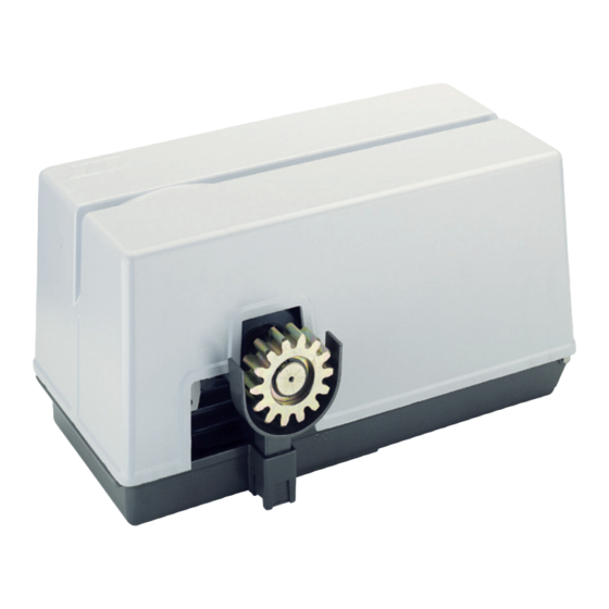
SUPER 4000
Scarica questo manuale sul tuo cellulare
Téléchargez ce manuel sur votre mobile
Download this manual on your mobile
Laden Sie dieses Handbuch auf Ihr Handy herunter
Descarga este manual en tu móvil
Operatore
Operateur
Operator
Torantrieb
Operador
SUPER 4000 FCE
SUPER 4000 FCM
SUPER 4000 FCE ICE
SUPER 4000 FCE sQ
SUPER 4000 FCE ICE sQ
Die korrekte Bedienung des Bedieners ist nur gewährleistet, wenn er von einem RIB-Bedienpanel verwaltet wird
ITALIANO pag. 05 / FRANÇAIS pag. 16 / ENGLISH page 27/ DEUTSCH pag. 38 / ESPAÑOL pag. 49
Alimentazione
Peso max cancello
Alimentation
Poids maxi portail
Power Supply
Max gate weight
Stromspannung
Max Torgewicht
Alimentacion
Peso máx verja
380-400V 50/60Hz
4000 kg
Il corretto funzionamento dell'operatore è garantito solo se viene gestito da un quadro di comando RIB
Le bon fonctionnement de l'opérateur n'est garanti que s'il est géré par un panneau de contrôle RIB
The correct operation of the operator is guaranteed only if it is managed by a RIB control panel
El funcionamiento correcto del operador solo está garantizado si está gestionado por un panel de control RIB
con / avec / with / mit
L1/R2-CRX
Disegni tecnici per progetti
Dessins techniques pour les projets
Technical drawings for projects
Technische Zeichnungen für Projekte
Dibujos técnicos para proyectos.
Manuali online interattivi
Manuels interactifs en ligne
Interactive online manuals
Interaktive Online-Handbücher
Manuales interactivos en línea.
Spinta max
Coppia max
Poussée maxi
Couple maxi
Max Thrust
Max torque
Max Schubkraft
Max. Drehmoment
Max Empuje
Coppia max
6600/5380 N
280/226 Nm
Vedere pagina 15
Voir page 27
See page 39
Siehe Seite 51
Ver página 63
Codice
Code
Code
Code
Codigo
AA31030
AA31031
AA31032
AA36061
AA36075
Publicité

Manuels Connexes pour RIB SUPER 4000 FCE


Sommaire des Matières pour RIB SUPER 4000 FCE
- Page 1 Le bon fonctionnement de l’opérateur n’est garanti que s’il est géré par un panneau de contrôle RIB The correct operation of the operator is guaranteed only if it is managed by a RIB control panel Die korrekte Bedienung des Bedieners ist nur gewährleistet, wenn er von einem RIB-Bedienpanel verwaltet wird El funcionamiento correcto del operador solo está...
- Page 2 2° - En ce qui concerne la section et le type des câbles, RIB conseille d’utiliser un câble de 2° - Per la sezione ed il tipo dei cavi la RIB consiglia di utilizzare un cavo di tipo H05RN-F con type H05RN-F ayant une section minumum de 1,5 mm 2 et de toute façon, s’en tenir à...
- Page 3 Kontaktöffnung von 3 mm), der ein von den internationalen Normen 2° - For the section and the type of the cables RIB advices to use a cable of H05RN-F type anerkanntes Konformitätszeichen besitzt. Solch ein Geraet muss vor Vandalismus with 1,5 sqmm minimum section and, however, to keep to the IEC 364 and installation geschuetzt werden (z.B.mit einen Schluesselkatsten in einem Panzergehaeuse).
- Page 4 L’eliminazione dei materiali va fatta rispettando le norme vigenti. Non gettate il vostro 2° - Para la sección y el tipo de los cables, RIB aconseja utilizar cables de tipo H05RN-F con apparecchio scartato, le pile o le batterie usate nei rifiuti domestici. Avete la responsabilità di sección mínima de 1,5 mm 2 e igualmente atenerse a la norma IEC 364 y a las normas de...
- Page 5 LAYOUT IMPIANTO A - Operatore SUPER 4000 B - Fotocellule esterne C - Cremagliera D - Selettore a chiave E - Antenna radio F - Lampeggiatore H - Colonnina portafotocellula I - Fotocellula per protezione interna L - Costa meccanica M - Costa meccanica o elettrica con sistema RED (Radio Edge Device) CARATTERISTICHE TECNICHE CARATTERISTICHE TECNICHE...
- Page 6 INSTALLAZIONE SUPER 4000 CONTROLLO PRE-INSTALLAZIONE - IL CANCELLO DEVE MUOVERSI SENZA ATTRITI - N.B. È obbligatorio uniformare le caratteristiche del cancello alle norme e leggi vigenti. La porta può essere automatizzata solo se in buono stato e se rispondente alla norma EN 12604.
- Page 7 «A» in senso antiorario. Per ripristinare il funzionamento elettrico operare in senso contrario (fig. 7). REGOLAZIONE FINECORSA SUPER 4000 FCE (Fig. 7) Per la regolazione: sbloccare i dadi G. Stabilito il senso di spostamento della camme H sia in apertura che in chiusura, posizionare a vista i due finecorsa F agendo sui pomoli P.
- Page 8 COLLEGAMENTI ELETTRICI L1 cod. AC08082 Manuali online interattivi Manuels interactifs en ligne Interactive online manuals Interaktive Online-Handbücher Manuales interactivos en línea.
- Page 9 RADIO Connettore per modulo radio ACG8069 Negativo alimentazione accessori a 24 Vdc RADIO Connettore per radio ricevitore rib ad innesto con alimentazione a 24 Vdc. A+ TEST Positivo per alimentazione autotest fotocellule a 24 Vdc Antenna radio 433 MHz COM A+ Comune dei contatti / Positivo 24 Vdc PROG.
- Page 10 B - SETTAGGI PED. Comando apertura pedonale (verde) START Comando impulso singolo (verde) CLOSE Comando Chiude (verde) DIP 1 (ON) - CONTROLLO PER MANUTENZIONE (PAG. 13) OPEN Comando Apre (verde) DIP 2 (ON) - PROGRAMMAZIONE TEMPI (PUNTO C) DIP 2-1 PROGRAMMAZIONE TEMPI APERTURA PEDONALE (PUNTO D) PROBE DIP 1-2...
- Page 11 R-AUX funziona normalmente come luce di cortesia per 3 minuti. totale del cancello. Il buzzer suonerà 1 volta per 1 secondo e il lampeggiatore lampeggerà per Tramite App RIB GATE è possibile configurare il funzionamento di questo relé a piacere. 4 secondi per segnalare l’attivazione della procedura.
- Page 12 FUNZIONAMENTO AD UOMO PRESENTE (con comando mantenuto) IN CASO DI GUASTO DELLE TELECOMANDO SICUREZZE DIP 6 ON => Esegue un comando ciclico dei comandi apre-stop-chiude-stop-apre-ecc. Se una delle due coste è guasta o impegnata per più di 5 s, o se una delle due fotocellule è DIP 6 OFF =>...
- Page 13 - Tempo diseccitazione 300 ms RISOLUZIONE PROBLEMI - Codici memorizzabili N° 1000 totali Dopo aver effettuato tutti i collegamenti seguendo attentamente lo schema ed aver posizionato - Tutti gli ingressi devono essere utilizzati come contatti puliti perchè l’alimentazione è il cancello in posizione intermedia, verificare la corretta accensione dei led rossi DL6, DL7, DL8, generata internamente (tensione sicura) alla scheda ed è...
- Page 14 DIFETTO SOLUZIONE Sulla scheda esistono dei fusibili ripristinabili che intervengono in caso di corto circuito interrompendo l'uscita a loro assegnata. A fronte di una ricerca guasti si consiglia di scollegare tutti i connettori estraibili e di inserirli Dopo aver effettuato i vari collegamenti e aver dato tensione, tutti i led sono spenti. uno a volta in modo da identificare più...
- Page 15 APP8054 Scheda APP+ APP8050 Scheda APP per gestire la centrale di comando per gestire la centrale di comando tramite Bluetooth tramite Bluetooth APP8064 Modulo Wi-Fi per Scheda APP8066 Modulo RJ45 per Scheda APP+ APP+ per gestire la centrale tramite rete per gestire la centrale tramite rete Wi-Fi locale (WLAN) dati locale (LAN)
- Page 16 ACG9492 LASERIB RILEVATORE di ACG9493 LASERIB RILEVATORE di sicurezza 5 m x 5 m sicurezza 10 m x 10 m ACG9490 STAFFA DI FISSAGGIO per ACG9491 TELECOMANDO per LASERIB regolare il rilevatore LASERIB di sicurezza LASERIB è un rilevatore di sicurezza tipo E (EN12453:2021) utilizzato per prevenire il contatto con parti mobili di serrande, porte sezionali e cancelli scorrevoli.
- Page 17 SCHÉMA DÉTAILLÉ DE L’INSTALLATION A - Operateur SUPER 4000 B - Photocellules p/protec. externe C - Cremaillere D - Selecteur E - Antenne radio F - Signal electrique H - Poteau zingué p/cellule ne I - Photocellules p/protection interne L - Barre palpeuse mécanique fixé sur pilier M - Barre palpeuse mécanique ou électrique avec système RED (Radio Edge Device) CARACTÉRISTIQUES TECHNIQUES CARACTERISTIQUES TECHNIQUES...
- Page 18 INSTALLATION SUPER 4000 CONTRÔLE PRÉ-INSTALLATION !! LE PORTAIL DOIT SE DÉPLACER SANS FROTTER !! N.B.: Il est impératif d’uniformiser les caractéristiques du portail avec les normes et les lois en vigueur. La porte peut être automatisée seulement si elle est en bon état et qu’elle est conforme à...
- Page 19 Pour ouvrir manuellement le portail en cas de panne de courant, il Faut ouvrir le carter et tourner la poignée «A» dans le sens anti-horaire. Pour revenir à un fonctionnement électrique tourner-le en sens contraire (Fig. 7). REGLAGE FIN DE COURSE SUPER 4000 FCE (Fig. 7) Pour procéder au réglage: - Débloquer les écrous G.
- Page 20 BRANCHEMENTS ÉLECTRIQUES L1 code AC08082 Manuali online interattivi Manuels interactifs en ligne Interactive online manuals Interaktive Online-Handbücher Manuales interactivos en línea.
- Page 21 A - BRANCHEMENTS PROG IL EST OBLIGATOIRE DE INSTAURER LA FICHE AVEC DIP 13 EN POSITION “ON”. MOTOR POWER 400 Vac + N L1 - N Alimentation 230 Vca 50/60 Hz (120 V 60 Hz sur demande) PROBE PAS DISPONIBLE Clignotant (max 40 W) ENCODER PAS DISPONIBLE...
- Page 22 B - RÉGLAGES DL13 L1 géré par APP (bleu) DL14 Encodeur active (rosso) DIP 1 CONTRÔLE D’ENTRETIEN (PAGE 25) (ON) DL15 Commande PROG et RADIO sur molex (vert) DIP 2 PROGRAMMATION DE LA DURÉE (ON) (POINT C) B.I.O. Commande de horloge (vert) DIP 2-1 PROGRAMMATION DES LAPS DE TEMPS D’OUVERTURE POUR PIÉTONS (DIP 2 ON suivi de PED.
- Page 23 4 secondes pour signaler l’activation de la procédure. Grâce à l’application RIB GATE, il est possible de configurer le fonctionnement de ce relais à 2 - Immédiatement puis appuyez une fois sur le même bouton de la ou des nouvelles volonté.
- Page 24 BOUTON DE FERMETURE (COM A+/CLOSE) Pendant l’ouverture, si EDGE 2 est activée, elle change le mouvement en fermeture. Si la barre À portail arrêté, ce bouton commande le mouvement de fermeture. palpeuse reste occupée, elle ne permet pas l’ouverture. Si vous n’en utilisez pas, ponter les bornes COM A+/EDGE1/EDGE2. BOUTON DE COMMANDE SIMPLE (COM A+/START) ALARME BARRE PALPEUSE DIP 6 ON =>...
- Page 25 - Puissance maximale du voyant portail ouvert 3 W (équivalent à 1 ampoule de 3 W SOLUTION DES PROBLEMES ou 5 voyant DEL avec résistance en Après avoir effectué tous les raccordements en suivant attentivement le schéma et avoir série de 2,2 KΩ) positionné...
- Page 26 TABLEAU RÉCAPITULATIF ALARMES VISUELLES ET SONORES SIGNALISATIONS EN COURS DE PROGRAMMATION ÉVÉNEMENT ÉTAT BUZZER ÉTAT CLIGNOTEUR ÉTAT LED DL1 DIP 1 ON (mode homme mort) Éteint Éteint Clignote 250 ms ON/OFF Ou panne d'une sécurité DIP 2 ON (programmation course totale) Éteint Éteint Clignote 500 ms ON/OFF...
- Page 27 EMETTEUR RADIO SUN MODULE RADIO 433MHz SUN 2CH cod. ACG6052 SUN 4CH cod. ACG6054 cod. ACG8069 SUN CLONE 2CH cod. ACG6056 SUN CLONE 4CH cod. ACG6058 SUN-PRO 2CH cod. ACG6210 SUN-PRO 4CH cod. ACG6214 APP8054 Carte APP+ APP8050 Carte APP pour gérer le tableau de contrôle via pour gérer le tableau de contrôle via Bluetooth 4.2...
- Page 28 ACG9492 DETECTEUR LASERIB de ACG9493 DETECTEUR LASERIB de sécurité - 10 m x 10 m sécurité - 5 m x 5 m ACG9490 SUPPORT DE MONTAGE ACG9491 TÉLÉCOMMANDE pour pour LASERIB régler le détecteur LASERIB de sécurité LASERIB est un détecteur de sécurité de type E (EN12453:2021) utilisé pour empêcher le contact avec les parties mobiles des volets roulants, des portes sectionnelles et des portails coulissants.
- Page 29 SYSTEM LAY-OUT A - SUPER 4000 operator B - Photoelectric cells (external) C - Rack D - Key selector E - Tuned aerial F - Flashing lamp H - Galvanized column for P.E. cells I - Photo electric cells (internal) L - Safety strip fixed to column M - Mechanical or electrical safety strip with RED (Radio Edge Device) system TECHNICAL FEATURES...
- Page 30 INSTALLATION SUPER 4000 CHECKING BEFORE THE INSTALLATION !! THE GATE SHALL MOVE FRICTIONLESS !! N.B.: Gate features must be uniformed with the standards and laws in force. The door/gate can be automated only if it is in a good condition and its conditions comply with the EN 12604 norm.
- Page 31 To open the gate manually, in open the motor cover and turn the knob «A» anti-clockwise. To restore electric working you have to turn the lever clockwise (Fig. 7). LIMIT SWITCH ADJUSTMENT SUPER 4000 FCE (Fig. 7) To adjust the assembly: release nuts G, after establishing the direction of movement of cam H for opening and closing, position the two limit switches, F, by turning knobs P and judging by sight.
- Page 32 ELECTRIC CONNECTIONS L1 code AC08082 Manuali online interattivi Manuels interactifs en ligne Interactive online manuals Interaktive Online-Handbücher Manuales interactivos en línea.
- Page 33 + 24 Vdc accessories power supply / Common contacts RADIO Connector for radio module ACG8069 - 24 Vdc accessories power supply RADIO Connector for radio receiver RIB, 24 Vdc supply A+ TEST + 24 Vdc photocells self-test power supply 433 MHz Radio antenna COM A+ Common contacts / Positive 24 Vdc PROG.
- Page 34 POINT B - SETTINGS OPEN OPEN command (NO) (green) DIP 1 MAINTENANCE CHECK (See Page 36) PROBE DIP 2 TIMES PROGRAMMING (See Point C) IS NOT AVAILABLE DIP 2-1 PROGRAMMING OF PEDESTRIAN OPENING (See Point D) DIP 1-2 SAVE/DELETE RADIO CODES FOR COMPLETE OPENING (DIP 1 ON followed by DIP 2 ON) POINT C - TIMES PROGRAMMING (POINT E) DIP 1-3...
- Page 35 2 - Immediately then press the same button once on the new remote control(s) you want ALL RADIO CODES FOR TOTAL OPENING CANCELLATION PROCEDURE to register. The buzzer will sound 1 time to confirm the registration of each new remote Cancellations can only be performed when gate is stationary.
- Page 36 DIP 4 ON => if an obstacle is placed in range of the photocells when the gate is closed and Connect the flashing light to the blinker output, use flashing lights ACG7072 and bulbs of 40 the command to open is given, the gate opens (the photocells do not work while W maximum.
- Page 37 After having carried out all connections, by carefully following the layout and having positioned the gate in intermediate position, check the correct ignition of red LEDS DL6, DL7, DL8, DL9 and DL10. In case of no ignition of the LEDS, always with gate in intermediate position, check the following and replace any faulty components.
- Page 38 FAULT SOLUTION After having carried out the various connections and having supplied voltage, all the LEDS are On the board there are resettable fuses which intervene in the event of a short circuit, switched OFF. interrupting the output assigned to them. In the event of troubleshooting, it is advisable to disconnect all the removable connectors and insert them one at a time in order to more easily identify the cause of the fault.
- Page 39 ACCESSORIES - For the connections and the technical data of the optional equipments follow the relevant handbooks. APP8050 APP card APP8054 APP+ card to manage the control panel using to manage the control panel using Bluetooth 4.2 transmission Bluetooth 4.2 transmission APP8064 Wi-Fi module for APP+ card APP8066 RJ45 module for APP+ card to manage the control panel using the...
- Page 40 ACG9492 LASERIB DETECTOR for ACG9493 LASERIB DETECTOR for safety - 5 m x 5 m safety - 10 m x 10 m ACG9490 MOUNTING BRACKET for ACG9491 REMOTE CONTROL LASERIB to adjust the safety LASERIB detector LASERIB is a type E safety detector (EN12453:2021) used to prevent contact with moving parts of rolling shutters, sectional doors and sliding gates. LASERIB offers optimal security at and around the door threshold.
- Page 41 ANLAGEN LAY-OUT A - Torantrieb SUPER 4000 B - Photozelle Toraussenseitig C - Zahnstange D - Schlusselschalter E - Antenne F - Blinkleuchte H - Verzinkte Metallsäule als Photozellentrager I - Photozelle - Torinnenseitig L - Sicherheitskontaktleiste auf dem Schiebetor M - Mechanische oder elektrische Kontaktleiste mit Red (Radio Edge Device) System TECHNISCHE EIGENSCHAFTEN TECHNISCHE EIGENSCHAFTEN...
- Page 42 INSTALLATION SUPER 4000 VOR DER MONTAGE AUSZUFÜHRENDE ÜBERPRÜFUNGEN !! DAS TOR MUSS REIBUNGSFREI LAUFEN !! ANMERKUNG: Es ist erforderlich, die Charakteristiken des Tors an die geltenden Normen und Gesetze anzupassen. Das Tor kann nur automatisch Angeschlossen werden, wenn es in einem einwandfreien Zustand ist und der EN12604 entspricht. - Das Tor welches keine Gehfluegelfunktion hat,in diesem Fall ist es erforderlich das Tor mit der norm EN 12453 punkt 6.5.1 in Einklang zu bringen (z.B.
- Page 43 Uhrzeigersinn. Um das Schiebetor wieder in Betrieb zu setzen, drehen Sie den Griff in die umgekehrte Richtung (Abb. 7). EINSTELLUNG DES ENDSCHALTERS SUPER 4000 FCE (Abb. 7) Zur Einstellung sind die Muttern G zu lösen: anschließend sind nach Festlegung der Bewegungsrichtung des Nockens H für Öffnung und Schließung die beiden Endschalter F...
- Page 44 ELEKTROANSCHLÖÜSSE L1 Kode AC08082 Manuali online interattivi Manuels interactifs en ligne Interactive online manuals Interaktive Online-Handbücher Manuales interactivos en línea.
- Page 45 Positive Ladung für die Speisung der Zubehöre zu 24 Vdc RADIO Verbinder für Radio-Modul ACG8069 Negative Ladung für die Speisung der Zubehöre zu 24 Vdc Verbinder für Radioempfänger RIB Steckverbindung mit Speisung zu 24 RADIO A+ TEST Positive Ladung für die Speisung für Fotozellen Selbstkontrolle...
- Page 46 B - EINSTELLUNGEN DL14 Encoder aktiviert (Rot) DL15 PROG- und RADIO-Befehle (am MOLEX-Anschluss) (Grün) DIP 1 WARTUNGSÜBERPRÜFUNG (SIEHE SEITE 49) B.I.O Uhr Befehl (NO) (Grün) DIP 2 ZEITPROGRAMMIERUNG (ON) (PUNKT C) PED. Fußgänger Öffnungsbefehl (NO) (Grün) DIP 2 - 1 ZEITPROGRAMMIERUNG ÖFFNUNG FUSSGÄNGER (DIP 2 ON GEFOLGT VON DIP 1 ON) START Einzelimpulsbefehl (NO) (Grün)
- Page 47 R-AUX arbeitet normalerweise 3 Minuten lang als Zusatzbeleuchtung. 4 - Erneut DIP 1 und DIP 2 auf OFF stellen. Über die RIB GATE-App kann der Betrieb dieses Relais wie gewünscht konfiguriert werden. Die Programmierung kann nur bei stehendem Tor erfolgen.
- Page 48 Führt bei stillstehendem OFFenem Tor zur Schließung. FUNKTIONIERT IM “BEFEHL GEDRÜCKT GEHALTEN”-MODUS WENN DIE SICHERHEITSVORRICHTUNGEN TASTE ZUR FUSSGÄNGER-ÖFFNUNG (COM A+/PED.) FEHLGESCHLAGEN SIND Befehl für eine teilweise Öffnung mit nachfolgender Schließung. Wenn eine der Kontaktleisten ist defekt oder diese arbeit länger als 5 s, oder wenn eine der Während der Öffnung der Pause oder der Schließung der Fußgänger-Öffnung, kann die Öffnung Fotozellen defekt ist oder für mehr als 60 s arbeit, die OPEN, CLOSE, START und PED.- Befehle mit jedem mit dem Steckverbinder L1 verbundenem Befehl geöffnet werden.
- Page 49 - Empfangsfrequenz 433,92 MHz LÖSUNG VON PROBLEMEN - Impedanz 52 Ω - Empfindlichkeit >1 µV Nachdem alle Verbindungen sorgfältig dem Schema folgend ausgeführt wurden und das Tor - Kontrolle Rückkoppelung auf die mittlere Position gestellt wurde, das korrekte Einschalten der rot LEDs DL6, DL7, DL8, - Gespeicherte Codes 1000 DL9 und DL10 kontrollieren.
- Page 50 ÜBERSICHTSTABELLE DER VISUELLEN UND AKUSTISCHEN ALARMEN SIGNALISIERUNGEN WÄHREND DER PROGRAMMIERPHASE EREIGNIS STATUS BUZZER STATUS BLINKLEUCHTE STATUS LED DL 1 DIP 1 ON (“befehl gedrückt gehalten”-modus) Abgeschaltet Abgeschaltet Blinkt 250 ms ON/OFF oder defekt einer sicherheitsvorrichtung DIP 2 ON (laufprogrammierung ganz) Abgeschaltet Abgeschaltet Blinkt 500 ms ON/OFF...
- Page 51 FERNSENDER SUN RADIO-MODUL 433MHz SUN 2CH Kode ACG6052 SUN 4CH Kode ACG6054 Kode ACG8069 SUN CLONE 2CH Kode ACG6056 SUN CLONE 4CH Kode ACG6058 SUN-PRO 2CH Kode ACG6210 SUN-PRO 4CH Kode ACG6214 APP8050 APP-Karte APP8054 APP+-Karte um das Steuerung mit Bluetooth um das Steuerung mit Bluetooth 4.2-Übertragung zu verwalten 4.2-Übertragung zu verwalten...
- Page 52 ACG9492 LASERIB DETEKTOR für ACG9493 LASERIB DETEKTOR für Sicherheits - 10 m x 10 m Sicherheits - 5 m x 5 m ACG9490 MONTAGEHALTERUNG für ACG9491 FERNBEDIENUNG zum LASERIB Einstellen des LASERIB-Detektors für Befehl und Sicherheit LASERIB ist ein Sicherheitsmelder vom Typ E (EN12453:2021), der verwendet wird, um den Kontakt mit beweglichen Teilen von Rollläden, Sektionaltoren und Schiebetoren zu verhindern.
- Page 53 DISPOSICIÒN DE LA INSTALACIÒN A - Operador SUPER 4000 B - Fotocélulas externas C - Cremallera D - Interruptor de llave E - Antena de radio F - Intermitente H - Columnas para las fotocélulas I - Fotocélulas internas L - Costa mecánica M - Costa mecánica o eléctrica con sistema RED (Radio Edge Device) CARACTERÍSTICAS TÉCNICAS CARACTERÍSTICAS TÉCNICAS...
- Page 54 INSTALACIÓN SUPER 4000 CONTROL PRE-INSTALACIÓN ¡¡LA VERJA TIENE QUE MOVERSE SIN ROCES!! IMPORTANTE: Es obligatorio uniformar las características de la verja a las normas y leyes en vigor. La puerta puede ser automatizada sólo si se encuentra en buen estado y responde a la norma EN 12604.
- Page 55 Para restablecer el funcionamiento eléctrico, proceder en sentido contrario (fig. 7). REGULACIÓN DE LOS FINALES DE CARRERA SUPER 4000 FCE (Fig. 7) Para efectuar esta operación se deben aflojar las tuercas G. Una vez establecido el sentido de desplazamiento de la leva H para la apertura y el cierre, colocar a ojo los dos finales de carrera F y accionar los pomos P.
- Page 56 CONEXIONES ELÉCTRICAS L1 cód. AC08082 Manuali online interattivi Manuels interactifs en ligne Interactive online manuals Interaktive Online-Handbücher Manuales interactivos en línea.
- Page 57 Positivo 24 Vdc / Común de los contactos RADIO Conector para módulo radio ACG8069 Negativo 24 Vdc para alimentación accesorios RADIO Conector para radio receptor RIB con alimentación de 24 Vdc A+ TEST Positivo 24 Vdc para alimentación autotest fotocélulas Antenna radio 433 MHz COM A+ Común de los contactos / Positivo 24 Vdc...
- Page 58 B - AJUSTES DL14 señalización estado de decodificador (verde) DL15 Mando PROG y RADIO en MOLEX (NA) (verde) DIP 1 CONTROL DE MANTENIMIENTO (ON) (PÁGINA 61) B.I.O. Mando reloj (NA) (verde) DIP 2 PROGRAMACIÓN DE LOS TIEMPOS (ON) (PUNTO C) PED.
- Page 59 Espere 4 segundos para que finalice el procedimiento. La luz intermitente se apagará. A través de la aplicación RIB GATE es posible configurar la operación de este relé como se Si no desea utilizar esta función, configure el DIP 3 en ON para desactivarla.
- Page 60 Con la automatización abierta se inhiben todos los mandos. Durante la apertura, si EDGE 2 está ocupado, invierte el movimiento en cierre. Si el banda de Liberando el interruptor, o cuando expira la hora configurada, se obtendrá el cierre inmediato seguridad permanece presionado, no permite la apertura.
- Page 61 - Tensión de alimentación 230 o 120 V~ ±10% RESOLUCIÓN DE PROBLEMAS - Frecuencia 50/60 Hz Después de haber efectuado todas las conexiones siguiendo atentamente el esquema y haber - Absorción máxima tarjeta 30 mA posicionado el portón en posición intermedia, verifique el correcto encendido de los led rojos - Microinterruptor de red 100 ms DL6, DL7, DL8, DL9 y DL10.
- Page 62 TABLA SINÓPTICA DE LAS ALARMAS VISUALES Y ACÚSTICAS SEÑALIZACIONES EN FASE DE PROGRAMACIÓN EVENTO ESTADO DE BUZZER ESTADO DE L'INTERMITENTE ESTADO LED DL1 DIP 1 ON (modo persona presente) Apagado Apagado Parpadea 250 ms ON/OFF O bien avería de un seguro (modo funciona siempre) DIP 2 ON (programación carrera total) Apagado Apagado...
- Page 63 MÓDULO RADIO 433MHz TELEMANDO SUN SUN 2CH cód. ACG6052 SUN 4CH cód. ACG6054 cod. ACG8069 SUN CLONE 2CH cód. ACG6056 SUN CLONE 4CH cód. ACG6058 SUN-PRO 2CH cód. ACG6210 SUN-PRO 4CH cód. ACG6214 APP8054 Tarjeta APP+ APP8050 Tarjeta APP para administrar la unidad de control para administrar la unidad de control a través de Bluetooth 4.2 a través de Bluetooth 4.2...
- Page 64 ACG9492 DETECTOR LASERIB de ACG9493 DETECTOR LASERIB de seguridad - 5 m x 5 m seguridad - 10 m x 10 m ACG9490 SOPORTE DE MONTAJE ACG9491 MANDO A DISTANCIA para para LASERIB ajustar el detector LASERIB de seguridad LASERIB es un detector de seguridad tipo E (EN12453:2021) que se utiliza para evitar el contacto con las partes móviles de persianas enrollables, puertas seccionales y puertas correderas.
- Page 65 COLLEGAMENTI FOTOCELLULE - CONNEXIONS PHOTOCELLULE - PHOTOCELLS CONNECTIONS FOTOZELLEN VERBINDUNGEN - CONEXIONES FOTOCÉLULAS 2 fotocellule F97P, F97I con autotest 4 fotocellule NOVA sincronizzate con autotest 2 photocellules F97P, F97I avec autotest 4 photocellules NOVA synchronisées avec autotest 2 photocells F97P, F97I with self-test 4 NOVA photocells synchronized with self-test 2 Fotozellen F97P, F97I mit Selbstkontrolle 4 NOVA Photozellen synchronisiert mit Selbstkontrolle...
- Page 66 SUPER 4000 FCE CAL1001 BC07099 CME1095 BA20090 CVA1025 BA01510 AC08082 CVA1141 ACG7091 CVA1300 ACG1080 BA10105 CCU6307 CEL1433 CME8087 CTC1168 CTC1044 CVA1023 CTC1151 CTC1012 CTC1159 CTC1101 CME5105 CTC1409 CTC1127 CZM6008 CTC1084 CME1034 BA00150 CVA1361 CME1063 CVA1391 CME1998 CPL1020 CCU6207 CME1079 CPL1119...
- Page 67 SUPER 4000 FCM BA00290 CVA1141 BA03247MSU CVA1025 DTE8X20I CCA1462 BA01510 DRL8X17I DDD3MA DRL6X21I BC07099 DTB6X20I CEL1823 CPL1437 AC08082 CME1095 CPL1438 ACG1080 CVA2368 CAL1001 DTC3X18Z CEL1433 DTC6X12Z CCA1461 CVA1300 DRD6 BA10105 CME8087 CCU6307 CVA1023 CTC1168 CTC1044 CTC1159 CTC1012 CTC1101 CME5105 CTC1409 CTC1127 CZM6008 CTC1084...
- Page 68 Dichiarazione di incorporazione per le quasi-macchine - Direttiva Macchine 2006/42/CE, Allegato II., B Déclaration d’incorporation pour les quasi-machines - Directive Machines 2006/42/CE, Annexe II, B Declaration of incorporation for partly completed machinery - Machinery Directive 2006/42/EC, Annex II., B Einbauerklärung für unvollständige Maschinen - Maschinenrichtlinie 2006/42/EG, Anhang II, B Declaración de incorporación de una cuasi máquina - Directiva de Máquinas 2006/42/CE, Anexo II, B R.I.B.