Table des Matières
Publicité
Les langues disponibles
Les langues disponibles
Liens rapides
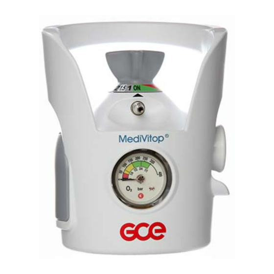
MediVitop®
PRESSURE REGULATORS INTEGRATED
WITH CYLINDER VALVE
DRUCKREGLER MIT FLASCHENVENTILEN
DETENDEURS INTEGRES
REGULADORES DE PRESIÓN INTEGRADOS
CON VÁLVULAS DE BOTELLA
RIDUTTORE DI PRESSIONE INTEGRATO CON VALVOLE
PER BOMBOLA
REDUKČNÍ VENTILY S INTEGROVANÝM
UZAVÍRACÍM VENTILEM PLYNOVÝCH LAHVÍ
INSTRUCTION FOR USE
BEDIENUNGSANLEITUNG
MODE D'EMPLOI
INSTRUCCIONES DE USO
ISTRUZIONI D´USO
NÁVOD K POUŽITÍ
GCE VALVES
EN
DE
FR
ES
IT
CS
Publicité
Table des Matières

Manuels Connexes pour GCE MediVitop


Sommaire des Matières pour GCE MediVitop
- Page 1 GCE VALVES MediVitop® PRESSURE REGULATORS INTEGRATED WITH CYLINDER VALVE DRUCKREGLER MIT FLASCHENVENTILEN DETENDEURS INTEGRES REGULADORES DE PRESIÓN INTEGRADOS CON VÁLVULAS DE BOTELLA RIDUTTORE DI PRESSIONE INTEGRATO CON VALVOLE PER BOMBOLA REDUKČNÍ VENTILY S INTEGROVANÝM UZAVÍRACÍM VENTILEM PLYNOVÝCH LAHVÍ INSTRUCTION FOR USE BEDIENUNGSANLEITUNG MODE D‘EMPLOI...
-
Page 2: Intended Use
The valve is designed according to EN ISO 10524-3 standard. 2. INTENDED USE MediVitop® Combination Valves are designed to be fitted to gas cylinders used for medical gases. These combination valves together with a gas cylinder form gas packages used either as gas supply point for medical devices (anaesthetic devices, ventilating devices, flowmeters, suction ejectors, incubators etc.) or for direct gas supply to a patient’s breathing mask, cannula... - Page 3 Only use the product and its associated equipment in well ventilated area. Before the first use the product shall be kept in its original package. If removed from service (for transport, storage) GCE recommends using the original package (including inner packing materials).
-
Page 4: Product Description
Serial number Compliance with 2010/35/EU Inlet connection Compliance with type 93/42/EEC Filling port type Reference number MediVitop® marking detail THE LAYOUT OF THE TEXT IS ONLY ILLUSTRATIVE, SOME VARIANTS MAY BE A DIFFERENT LAYOUT 4/59... - Page 5 MARKING DETAIL A – INLET STEM The combination valve is fitted to gas cylinder by a threaded inlet stem. The inlet stem can be taper threaded or parallel threaded with different size depending on the cylinder size and material. B – FILLING PORT A filling port is provided for filling the gas cylinder at a filling station, it has no function for pa- tient use.
-
Page 6: Use Of Product
The flow outlet “G“ is equipped with hose fitting (hose nipple) or a threaded type (for acces- sories to be connected via threaded connection). Movement of the flow outlet ‘G’ is normal due to the method of fixing in the main body. It doesn’t indicate a faulty flow outlet. - Page 7 Check that there is a gas flow at each “flow selector“set position in both anticlockwise and • clockwise turning direction (for instance by sound or checking presence of bubbles in a hu- midifier).. Turn off at the shut-off valve by turning the combination control knob“shut-off valve & flow •...
-
Page 8: Accessories
6.1.3. AFTER USE Turn off at the shut-off valve by turning the combination control knob“ shut-off valve & flow • selector“ in a clockwise direction to OFF position. Do not use excessive force (Maximum recommended closing torque is 3 Nm). Vent pressure from the connected devices. - Page 9 GCE product. 9.2. REPAIR AND SERVICE OPERATIONS Repairs and service can be only done by a GCE certified person who also holds all necessary certificates in compliance with national standards for mounting and repair of dedicated gas devices.
- Page 10 11. WARRANTY The Standard Warranty period is two years from date of receipt by the GCE Customer (or if this is not known 2 years from time of the product manufacture shown on the product). The standard warranty is only valid for products handled according to Instruction for use (IFU) and general industry good practice and standards.
- Page 11 Anforderungen der Normen EN ISO 10524-3 und EN ISO 10297. 2. ZWECKBESTIMMUNG MediVitop® Kombiventile wurden für den Anschluss an Gasflaschen konzipiert, die für medizini- sche Gase verwendet werden. Diese Kombiventile bilden zusammen mit einer Gasflasche eine Einheit, die entweder als Gasquelle für Medizingeräte (Anästhesiegeräte, Beatmungsgeräte, Flowmeter, Absaugejektoren, Inkubatoren etc.) oder für die direkte Gaszufuhr zur Atemmaske oder Nasen-...
- Page 12 Das Produkt und die zugehörigen Geräte nur in gut gelüfteten Räumen einsetzen. Vor Erstinbetriebnahme muss sich das Produkt in seiner Originalverpackung befinden. Im Falle der Außerbetriebsetzung (für Transport, Lagerung) empfiehlt GCE die Originalverpackung an- zuwenden. Es sind die nationalen Gesetze, Regelungen und Vorschriften zu Unfallverhütung und Umwelt- schutz beim Einsatz von medizinischen Gasen zu beachten.
- Page 13 Ventilausgang über die kalibrierten Düsen; Ausgangsdurchflüsse können mittels Steuergerät • geregelt werden Ventilausgang über die Schnellkupplung (der Ausgangsdurchfluss ist konstant) in Kombina- • tion mit dem Ventilausgang über die kalibrierten Düsen, in denen die Ausgangsdurchflüsse durch das Steuergerät geändert werden können KENNZEICHNUNG Typische MediVitop®-Ventilanordnung 13/59...
- Page 14 Eingangsanschluss Entspricht 93/42/EEC Füllanschluss Artikelnummer MediVitop® Kennzeichnung DAS LAYOUT DES TEXTES IST NUR ILLUSTRATIV, EINIGE VARIANTEN KÖNNEN EIN ANDERES LAYOUT SEIN A – ANSCHLUSSSTUTZEN Das Kombiventil wird mit einem Gewinde-Anschlussstutzen in die Gasflasche eingedreht. Der Anschlussstutzen ist entweder mit einem konischen oder einem zylindrischen Gewinde aus- gestattet und in verschiedenen Größen (für verschiedene Flaschengrößen und -materialien)
-
Page 15: Verwendung Des Produkts
Die Verbindung zum Patienten über den Flow-Anschluss „G“ kann entweder über einen Schlauchanschluss (Schlauchtülle) oder eine Gewindeverbindung (für Zubehör mit Gewindean- schluss) erfolgen. Der Flow-Anschluss „G“ ist nicht starr im Ventilkörper fixiert. Der Anschluss ist minimal beweg- lich. H – DRUCKANSCHLUSS – SCHNELLKUPPLUNG ODER ABLASSVENTIL (OPTIONAL) Der Druckanschluss ist ein direkter Anschluss an die Unterdruckkammer des Ventils, der mit einem spezifischen Steckanschluss oder Ablassventil ausgestattet ist. - Page 16 DICHTIGKEITSPRÜFUNG VOR DEM EINSATZ: Öffnen Sie langsam das Kombinationsabsperrventil, indem Sie die Steuergerätkombination • „Absperrventil und Durchfl usswähler“ langsam gegen den Uhrzeigersinn in die Stellung ON drehen. Prüfen Sie akustisch auf Leckage (charakteristisches Zischen). • Prüfen Sie, dass bei jeder Einstellung Gas fließt (gegen und im Uhrzeigersinn). •...
-
Page 17: Nach Dem Einsatz
Soll der Druckanschluss mit einem medizinischen Gerät verbunden werden, das einen hohen Gasflow erfordert (z. B. ein Lungenbeatmungsgerät, das einen Gasflow von 100 l/min bei ei- nem Mindestdruck von 2,8 bar erfordert), den für den Anschluss des medizinischen Geräts er- forderlichen Flowwert mit der Druck- und Flow-Charakteristik des Kombiventils vergleichen;... -
Page 18: Reparatur Und Wartung
Um weitere Informationen zu den in Ihrem Land verfügbaren Wartungsleistungen zu erhalten, setzen Sie sich bitte mit GCE oder dem für Ihr GCE Produkt zuständigen Vertriebshändler in Verbindung. Normalerweise kann das Kombiventil repariert werden, während es an der Gasflasche montiert ist. - Page 19 Alle zur Reparatur oder Wartung an GCE (oder autorisierte GCE Zentren) eingesandten Produk- te sind ordnungsgemäß zu verpacken, um Verunreinigungen oder Beschädigungen bei der Lagerung, beim Transport und bei der Handhabung zu vermeiden. Für Reparaturen ist eine kurze Fehler- oder Störungsbeschreibung sowie die Angabe einer Vorgangsnummer vorteilhaft.
- Page 20 Nr 3 – Post Filling Checks (= Überprüfung nach dem Füllen) Nr 4 – Valve assembly and filling instruction (=Ventilmontage und Füllanleitung) HERSTELLER: GCE, s.r.o. Tel: +420 569 661 111 Zizkova 381 Fax: +420 569 661 602 583 01 Chotebor http://www.gcegroup.com Tschechische Republik © GCE, s.r.o. 20/59...
-
Page 21: Avant-Propos
La vanne combinée est conçue conformément aux normes EN ISO 10524-3. 2. UTILISATION PRÉVUE Les vannes combinées MediVitop® sont destinées au montage sur des bouteilles de gaz médi- caux. Ces vannes combinées et les bouteilles de gaz sur lesquelles elles sont montées forment des ensembles gazeux. -
Page 22: Exigences De Sécurité Pendant L'exploitation, Le Transport Et Le Stockage
Utiliser le produit, y compris ses accessoires, uniquement dans des locaux bien aérés. Avant la première utilisation, le produit doit se trouver dans son emballage d´origine. En cas de mise hors d´utilisation (pour le transport, stockage,..), GCE recommande d´utiliser l´emballage d´origine (y compris le sac plastique intérieur et les capuchons). -
Page 23: Education Des Collaborateurs
La sortie de vanne via raccord rapide (la pression de sortie est alors constante) en combinai- • son avec la sortie de valve via orifices calibrés où les débits de sortie peuvent être modifiés à l'aide du bouton de commande DÉTAILS DU MARQUAGE Configuration typique MediVitop® vanne 23/59... - Page 24 Numéro de référence de remplissage Détails du marquage du MediVitop® LA MISE EN PAGE DU TEXTE EST UNIQUEMENT ILLUSTRATIVE, CERTAINES VERSIONS PEUVENT AVOIR UNE MISE EN PAGE DIFFÉRENTE A — RACCORD D’ENTRÉE La vanne combinée est montée sur la bouteille de gaz par un raccord d’entrée fileté. Ce raccord peut avoir un filetage conique ou cylindrique avec des tailles différentes suivant les dimensions...
-
Page 25: Utilisation Du Produit
La sortie de débit « G » est munie d’une olive de sortie pour flexible souple ou d’un raccord fileté (pour les accessoires à raccorder par raccord fileté). Le jeu de l’olive de sortie « G » est normal compte tenu de la méthode de fixation au corps principal. -
Page 26: Utilisation De La Vanne Combinee
TEST D'ÉTANCHÉITÉ ET DE FONCTIONNEMENT AVANT UTILISATION: Ouvrir lentement le robinet de fermeture combiné en tournant lentement le bouton de com- • mande combiné « robinet de fermeture et sélecteur de débit » dans le sens antihoraire en position ON. Ecouter pour vérifier s'il y a des fuites (une fuite serait entendue par un sifflement caractéris- •... -
Page 27: Après Utilisation
Si la sortie de pression doit être connectée à un dispositif médical qui nécessite un débit de gaz élevé (par exemple un ventilateur pulmonaire qui nécessite un débit de gaz de 100 l/min à la pression minimale de 2,8 bars), comparer le débit requis de la connexion du dispositif médical avec les caractéristiques de pression et de débit de la vanne combinée indiquées dans l'annexe N °. -
Page 28: Entretien, Durée De Vie Du Produit Et Maintenance
à la « Directive 2008/98/CE du Parlement européen et du Conseil relative aux déchets ». Conformément à l’article 33 du règlement REACH, la société GCE, s.r.o., en tant que fabricant responsable, s’engage à informer tous les clients, si les matériaux contiennent plus de 0,1 % ou plus de substances qui fi gurent sur la liste des substances extrêmement préoccupantes... -
Page 29: Légendes Des Pictogrammes
Tout produit renvoyé à GCE (ou à un centre agréé GCE) pour une réparation ou une mainte- nance doit être correctement emballé afin d’éviter une contamination ou un endommagement pendant le stockage, le transport et la manipulation. Pour les produits destinés à la réparation, il convient d’ajouter une description courte du pro- blème ou d’indiquer un numéro de réclamation. - Page 30 N°3 : Contrôles après remplissage N°4 : Instruction de montage et de remplissage de la valve FABRICANTE : GCE, s.r.o. Tel: +420 569 661 111 Zizkova 381 Fax: +420 569 661 602 583 01 Chotebor http://www.gcegroup.com République Tchèque © GCE, s.r.o. 30/59...
-
Page 31: Uso Previsto
EN ISO 10524-3. 2. USO PREVISTO Las válvulas compactas MediVitop® están diseñadas para ser montadas en las botellas de gas que se emplean para los gases de uso medicinal. Las válvulas compactas con la botella de gas, forman un conjunto para ser utilizado tanto como suministro de gas para dispositivos médicos... - Page 32 Antes de su primer aplicación debe estar el producto en su embalaje original. En caso de ser retirado el producto del servicio (a causa del transporte, del almacenaje), GCE recomienda usar el embalaje original (incluso los materiales para llenar el interior).
-
Page 33: Descripción Del Producto
Suministro de presión a tráves de una toma de presión (presión fija) y suministro de caudal a • través de un caudalímetro de aforos calibrados. El causal se puede ajustar a través de dicho caudalímetro. DETALLE DE MARCAJE Configuración habitual de la válvula MediVitop® 33/59... - Page 34 Número de referencia de llenado Detalle de marcaje de la MediVitop® EL DISEÑO DEL TEXTO ES SÓLO ILUSTRATIVO, ALGUNAS VARIANTES PUEDEN TENER UN DISEÑO DIFERENTE A - CONEXIÓN DE ENTRADA La válvula compacta se acopla a la botella de gas mediante una toma de rosca. La rosca puede ser cónica o paralela, de distinto calibre en función del tamaño y material de la botella.
-
Page 35: Empleo Del Producto
La espiga G dispone de un acople para manguera (tipo boquilla) o una conexión roscada (para accesorios que se conecten mediante rosca). Es normal que la espiga G se mueva ya que está sujeta al cuerpo y esto no indica que exista ningúntipo de avería. - Page 36 PRUEBA FUNCIONAL Y DE FUGAS ANTES DE LA UTILIZACIÓN: Abrir lentamente la válvula de corte girando el mando de la válvula de corte y caudalímetro • en sentido contrario de las agujas del reloj hasta la posición ON. Compruebe que no existe una fuga (se escucharia una perdida de gas en caso de fuga). •...
- Page 37 Una apertura rápida de la válvula de corte puede ser peligrosa y provocar una ignición o explosión por golpe de ariete. Una apertura insuficiente de la válvula de corte podría reducir el valor de caudal suministrado. Si la válvula compacta está equipada tanto con caudalímetro como con toma de presión, no los utilice simultaneamente.
-
Page 38: Vida Útil Del Producto
útil. Use únicamente componentes originales GCE. Todos los productos que se devuelvan a GCE (o a un centro autorizado por GCE) para su re- paración o mantenimiento irán debidamente empaquetados para evitar la contaminación y los daños durante el almacenamiento, transporte y manipulación. - Page 39 El período de garantía estándar es de dos años, a partir de la fecha de recepción por parte del cliente de la GCE o, si esta no se conoce, 2 años de la fecha de fabricación que se muestra en el producto.
- Page 40 N.º 3 : Comprobaciones posteriores al llenado N.º 4 : Instrucciones de montaje y llenado de la válvula MANUFACTURER: GCE, s.r.o. Tel: +420 569 661 111 Zizkova 381 Fax: +420 569 661 602 583 01 Chotebor http://www.gcegroup.com República Checa © GCE, s.r.o. 40/59...
-
Page 41: Profilo Dell'utente
(apparecchiature per anestesia, ventilatori, flussometri, aspiratori, incubatrici, ecc.) o per il dosaggio diretto del gas alla maschera o alla cannula o umidificatore. Le valvole riduttrici GCE sono destinate all'uso con i gas medicali di seguito elencati: Ossigeno •... - Page 42 Usare il prodotto, inclusi gli accessori, solo in locali ben ventilati. Il prodotto va conservato nel suo imballo originale fino al suo primo utilizzo. Nel caso di ritiro del prodotto dall´ esercizio (per il trasporto, immagazzinamento), GCE raccomanda di usare l´imballo originale (inclusi i materiali d’imballaggio interni).
-
Page 43: Descrizione Del Prodotto
4. ISTRUZIONI PER IL PERSONALE Secondo la Direttiva sui Dispositivi Medici 93/42/CEE Il fornitore del prodotto deve assicurare vengano forniti istruzioni per l'uso e dati sulle prestazioni dello stesso a tutto il personale addetto alla sua manipolazione. Non utilizzare il prodotto senza una corretta formazione ed un utilizzo sicuro dello stesso come definito nel presente documento “Istruzione per l'uso”. - Page 44 Tipo di raccordo Numero di riferimento di riempimento MediVitop® marcatura dettagli IL LAYOUT DEL TESTO È PURAMENTE ILLUSTRATIVO, ALCUNE VARIANTI POSSONO AVERE UN LAYOUT DIFFERENTE A – ATTACCO BOMBOLA La valvola riduttrice è provvista di uno stelo filettato per il montaggio sulla bombola. La filettatura di tale stelo può...
-
Page 45: Uso Del Prodotto
L'uscita di flusso “G“ è dotata di un attacco per il tubo (raccordo portagomma) o un attacco filettato (per connettere gli accessori dotati di connessione filettata). Un lieve movimento dell'uscita di flusso “G” è normale e dovuta al sistema di fissaggio al corpo principale;... -
Page 46: Uso Dell'erogatore Della Valvola Combinata
TEST PREVIO DI TENUTA E FUNZIONAMENTO: Aprire lentamente la valvola di intercettazione combinata ruotando lentamente in senso • antiorario la manopola di regolazione combinata «valvola di intercettazione e selettore di erogazione» fino alla posizione ON. Verificare la presenza di eventuali fughe di gas (una fuga si rileva grazie al caratteristico •... - Page 47 Se l'uscita a pressione deve essere collegata a un dispositivo medico che richiede un'alta portata (per es. un ventilatore polmonare che necessita una portata di 100 l / min a una pres- sione minima di 2,8 bar), verificare la conformità della portata richiesta dal dispositivo medico collegato con le caratteristiche di portata e pressione della valvola riduttrice riportate nell'al- legato n.
- Page 48 Consiglio 2008/98/CE relativa ai rifiuti. Ai sensi dell'articolo n. 33 del regolamento REACH GCE, S.R.O. in qualità di produttore e responsabile è tenuta ad informare tutti i Clienti se i materiali contengono lo 0,1% o più di sostanze incluse nella lista delle Sostanze estremamente problematiche (SVHC).
- Page 49 11. GARANZIA Il normale periodo di garanzia è di due anni dalla data di ricevimento del cliente GCE (o se questa data non è conosciuta, due anni dalla data di produzione marcata sul prodotto). La garanzia è da considerarsi valida solo per i prodotti usati secondo le istruzioni riportate sul manuale d’uso ed in base alle buone norme e standard del produttore...
- Page 50 N 3: Controlli post-riempimento N 4: Instruzioni per il montaggio e il riempimento della valvola FABBRICANTE: GCE, s.r.o. Tel: +420 569 661 111 Zizkova 381 Fax: +420 569 661 602 583 01 Chotebor http://www.gcegroup.com Repubblica Ceca © GCE, s.r.o. 50/59...
-
Page 51: Účel Použití
Ventil je navržen dle norem EN ISO 10524-3. 2. ÚČEL POUŽITÍ Kombinované ventily MediVitop® jsou určeny pro montáž na tlakové lahve používané pro medi- cinální plyny. Tyto kombinované ventily s tlakovou lahví tvoří sestavy, které slouží buď jako zdroj plynu pro zdravotnická zařízení (anesteziologické přístroje, ventilační přístroje, průtokoměry, sací... - Page 52 Výrobek, včetně příslušenství, používejte pouze v dobře odvětrávaných prostorech. Před prvním použitím musí být výrobek ve svém originálním obalu. V případě stažení z provozu (pro přepravu, skladování) doporučuje GCE použít originální balení (včetně vnitřních výplňových materiálů). Musí být dodržovány národní zákony, vyhlášky a předpisy pro medicinální plyny, bezpečnost práce a ochranu životního prostředí.
-
Page 53: Popis Výrobku
4. INSTRUKTÁŽ PRACOVNÍKŮ Dle medicinální direktivy 93/42/EHS má poskytovatel zařízení povinnost poskytnout všem uživatelům a osobám manipulujícím s výrobkem návod k použití & technickou dokumentaci pro daný produkt. Nepoužívejte výrobek bez řádného seznámení se s výrobkem a jeho bezpečným provozem, jak je popsáno v tomto návodu k použití. - Page 54 93/42/EEC Typ plnícího Objednávací číslo portu MediVitop® značení ROZMÍSTĚNÍ TEXTU JE POUZE ILUSTRATIVNÍ. U NĚKTERÝCH VARIANT MŮŽE BÝT JINÉ ROZMÍSTĚNÍ TEXTU A – VSTUPNÍ PŘÍPOJKA Výrobek je připojen k tlakové lahvi pomocí vstupní přípojky se závitem. Přípojka může mít kuže- lový...
-
Page 55: Použití Výrobku
H – TLAKOVÝ VÝSTUP - RYCHLOUPÍNACÍ SPOJKA NEBO ODVĚTRÁVACÍ VENTIL (VOLITELNÁ VÝBAVA) Kombinovaný ventil může být osazen tlakovým výstupem nebo odvětrávacím ventilem. Ten je přímo napojen do nízkotlaké části ventilu a je osazen specifickou rychloupínací spojkou, nazývanou také „rychlospojka“. Uživatel může připojit další zařízení k výstupu plynu pomocí speciálního protikusu - rychlospojkového nástavce (viz příloha č.2). - Page 56 U kombinovaných ventilů s tlakovým výstupem zkontrolujte funkčnost připojením a odpojení • rychlospojky. Pokud dochází k úniku plynu, aplikujte postup popsaný v kapitole 6.2.3. a vraťte ventil na servis. Náhlé otevření uzavíracího ventilu může způsobit nebezpečí vznícení nebo exploze vyplýva- jící...
- Page 57 6.1.3. PO POUŽITÍ Uzavřete uzavírací ventil - kombinovaný ovladač "uzavíracího ventilu & průtočné hlavy" v • pozici OFF. Nepoužívejte nadměrnou sílu (max. doporučený utahovací moment je 3 Nm). Z připojených zařízení odvětrejte tlak plynu. • Odpojte veškerá připojená zařízení od uživatelských výstupů. •...
- Page 58 Pro informace o servisu ve vašem okolí prosím kontaktujte GCE nebo distributora GCE výrobků. Opravy kombinovaných ventilů GCE, které nemusí být prováděny certifikovanou osobou pro opravy, se týkají výměny následujících poškozených součástek: kryt, •...
- Page 59 11. ZÁRUKA Běžná záruční doba na výrobek je dva roky od data doručení výrobku zákazníkům GCE (pokud není datum doručení známo, počítá se záruční doba od data uvedeného na výrobku). Běžná záruka je platná pouze na výrobky, které jsou používány dle návodu k použití, předepsa- ných norem a správné...
- Page 60 IRELAND GERMANY CZECH REPUBLIC FRANCE HUNGARY ROMANIA UNITED STATES ITALY SPAIN OF AMERICA PORTUGAL CHINA MEXICO INDIA PANAMA Manufacturer: GCE, s.r.o. Žižkova 381, 583 01 Chotěboř, Česká republika http://www.gcegroup.com Doc. Nr.: IFU0079; DOI: 2021-01-08; Rev.: 07; TI: A5, CB, V1...