Publicité
Les langues disponibles
Les langues disponibles
Liens rapides
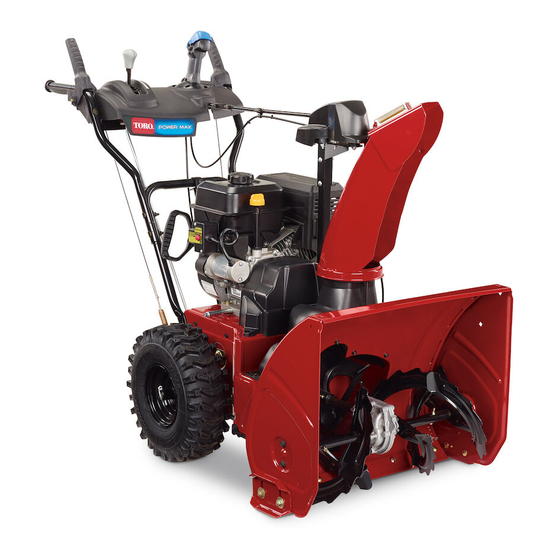
Power Max
Model No. 37798—Serial No. 400000000 and Up
Model No. 37799—Serial No. 400000000 and Up
Introduction
This machine is intended to be used by residential
homeowners. It is designed primarily for removing
snow from paved surfaces, such as driveways and
sidewalks, and other surfaces for traffic on residential
or commercial properties. It is not designed for
removing materials other than snow.
Read this information carefully to learn how to operate
and maintain your product properly and to avoid
injury and product damage. You are responsible for
operating the product properly and safely.
You may contact Toro directly at www.Toro.com
for product safety and operation training materials,
accessory information, help finding a dealer, or to
register your product.
Whenever you need service, genuine Toro parts, or
additional information, contact an Authorized Service
Dealer or Toro Customer Service and have the model
and serial numbers of your product ready.
identifies the location of the model and serial numbers
on the product. Write the numbers in the space
provided.
Important:
With your smartphone or tablet, scan
the QR code on the serial number decal to access
warranty, parts, and other product information.
1. Model and serial number location
Model No.
Serial No.
© 2018—The Toro® Company
8111 Lyndale Avenue South
Bloomington, MN 55420
®
824 OE and 826 OXE Snowthrower
Figure 1
Figure 1
Register at www.Toro.com.
This manual identifies potential hazards and has
safety messages identified by the safety-alert symbol
(Figure
2), which signals a hazard that may cause
serious injury or death if you do not follow the
recommended precautions.
This manual uses 2 words to highlight information.
Important calls attention to special mechanical
information and Note emphasizes general information
worthy of special attention.
Important:
If you are using this machine above
1500 m (5,000 ft) for a continuous period, ensure
that the High Altitude Kit has been installed
so that the engine meets CARB/EPA emission
regulations. The High Altitude Kit increases
engine performance while preventing spark-plug
fouling, hard starting, and increased emissions.
Once you have installed the kit, attach the
high-altitude label next to the serial decal on the
machine. Contact any Authorized Toro Service
Dealer to obtain the proper High Altitude Kit and
high-altitude label for your machine. To locate
a dealer convenient to you, access our website
at www.Toro.com or contact our Toro Customer
Care Department at the number(s) listed in your
Emission Control Warranty Statement. Remove
the kit from the engine and restore the engine to
its original factory configuration when running the
engine under 1500 m (5,000 ft). Do not operate an
engine that has been converted for high-altitude
use at lower altitudes; otherwise, you could
g219962
overheat and damage the engine.
If you are unsure whether or not your machine has
been converted for high-altitude use, look for the
following label
Original Instructions (EN)
Form No. 3423-315 Rev B
Operator's Manual
Figure 2
Safety-alert symbol
(Figure
3).
All Rights Reserved *3423-315* B
Printed in Mexico
g000502
Publicité

Manuels Connexes pour Toro 37798


Sommaire des Matières pour Toro 37798
- Page 1 If you are using this machine above additional information, contact an Authorized Service 1500 m (5,000 ft) for a continuous period, ensure Dealer or Toro Customer Service and have the model that the High Altitude Kit has been installed and serial numbers of your product ready.
- Page 2 Operating the Auger/Impeller Drive....15 Operating the Quick Stick®....... 15 Clearing a Clogged Discharge Chute ....16 Operating Tips ..........17 After Operation ............ 17 After Operation Safety ........17 Preventing Freeze-up after Use ......17 decal127-9363 Maintenance ............18 Figure 3 Recommended Maintenance Schedule(s) ...
- Page 3 • Keep clear of any discharge opening. Keep bystanders, especially small children, out of the operating area. • Never allow children to operate the machine. Safety and Instructional Decals Safety decals and instructions are easily visible to the operator and are located near any area of potential danger.
- Page 4 decal133-8061 133-8061 decal137-6198 137-6198 1. Cutting/dismemberment 2. Warning—shut off the hazard of the fingers or engine before using the hand, impeller—do not tool to clear the chute. place your hand in the chute. decal121-1240 121-1240 Order Part No. 138-8487 1. Traction drive—squeeze the lever to engage; release the 4.
- Page 5 Setup Installing the Upper Handle No Parts Required Procedure g252379 Installing the Chute No Parts Required Procedure g252568...
- Page 6 Installing the Traction-Control Linkage No Parts Required Procedure g252391...
- Page 7 Installing the Chute-Control Rod No Parts Required Procedure g257848...
- Page 8 Installing the Snow-Cleanout Tool No Parts Required Procedure g252394 Checking the Engine-Oil Level No Parts Required Procedure Note: Your machine comes with oil in the engine crankcase. Before starting the engine, check the oil level and add oil if necessary. Refer to Checking the Engine-Oil Level (page 19).
- Page 9 Checking the Tire Pressure No Parts Required Procedure g252396 Checking the Skids and Checking the Operation of Scraper the Traction Drive No Parts Required No Parts Required Procedure Procedure Refer to Checking and Adjusting the Skids and CAUTION Scraper (page 19).
- Page 10 Product Overview g001011 Figure 10 The machine should move rearward. If the machine does not move or moves forward, complete the following: Release the traction lever and shut off the engine. Disconnect the trunnion from the speed-selector lever. Turn the trunnion downward (clockwise) on the speed-control rod.
- Page 11 Authorized Service Dealer or authorized Toro • Fill the fuel tank outdoors when the engine is cold. distributor or go to www.Toro.com for a list of all Replace the fuel cap securely and wipe up spills. approved attachments and accessories.
- Page 12 Filling the Fuel Tank During Operation • For best results, use only clean, fresh (less than 30 days old), unleaded gasoline with an octane During Operation Safety rating of 87 or higher ((R+M)/2 rating method). • Shut off the engine before unclogging the •...
- Page 13 when making any repairs, adjustments, or inspections. • Never operate the machine at high transport speeds on slippery surfaces. Starting the Engine Electric-Start Model Note: To use the electric starter (electric-start models only), connect a power cord to the plug-in first and then to a power outlet.
- Page 14 Standard Model g254928 Figure 16 Shutting Off the Engine g252411 Figure 17 Operating the Traction To engage the traction drive, squeeze the left (traction) lever to the handgrip (Figure 18). Drive CAUTION If the traction drive is not properly adjusted, the machine may move in the direction opposite of what you intended, causing injury and/or property damage.
- Page 15 Operating the Speed WARNING Selector If the auger and impeller continue to rotate when you release the The speed selector has 6 forward and 2 reverse auger/impeller lever, you could seriously gears. To change speeds, release the traction lever injure yourself or others. and shift the speed-selector lever to the desired Do not operate the machine.
- Page 16 Clearing a Clogged • If the chute does not move, refer to Adjusting the Discharge-Chute Latch (page 24). Discharge Chute • If the chute does not turn as far to the left as it does to the right, ensure that the cable is routed to the inside of the handles.
- Page 17 Operating Tips After Operation DANGER After Operation Safety When the machine is in operation, the impeller • Never store the machine with fuel in the fuel and auger rotate and can injure or amputate tank inside a building where ignition sources are hands or feet.
- Page 18 • Check all fasteners at frequent intervals for proper tightness to ensure that the machine is in safe working condition. • Do not change the governor settings on the engine. Purchase only genuine Toro replacement parts and accessories.
- Page 19 Checking the Engine-Oil Level Service Interval: Before each use or daily—Check the engine-oil level and add oil if necessary. g252395 Checking and Adjusting the Important: The auger blades must be supported above the ground by the skids. Skids and Scraper Ensure that the scraper is 3 mm (1/8 inch) above Service Interval: Yearly—Check the skids and and parallel to a level surface.
- Page 20 Checking and Adjusting the Traction Cable Service Interval: After the first 2 hours—Inspect the traction cable and adjust it if necessary. Yearly—Inspect the traction cable and adjust or replace it if necessary. If the machine does not drive in the forward or reverse speeds or it drives when you release the traction lever, adjust the traction cable.
- Page 21 Checking and Adjusting the Checking the Auger/Impeller Cable Auger-Gearbox-Oil Level Service Interval: After the first 2 hours—Inspect the Service Interval: Yearly—Check the auger-gearbox auger/impeller cable and adjust it if oil and add oil if necessary. necessary. Move the machine to a level surface. Yearly—Inspect the auger/impeller cable and Clean the area around the pipe plug (Figure...
- Page 22 Changing the Engine Oil Lubricating the Hex Shaft Service Interval: Yearly—Lubricate the hex shaft. Service Interval: After the first 5 hours—Change the engine oil. Lightly lubricate the hex shaft yearly with automotive engine oil (Figure 33). Yearly—Change the engine oil. If possible, run the engine for a few minutes before changing the oil because warm oil flows better and carries more contaminants.
- Page 23 Wait until the engine is cool to replace the spark plug. Install the new spark plug, tighten it firmly, and Use a Toro spark plug or equivalent (Champion® attach the ignition wire to the spark plug. RN9YC or NGK BPR6ES).
- Page 24 Adjusting the Discharge-Chute Latch If the discharge chute does not lock into the desired position or does not unlock so that you can move it to another position, adjust the discharge-chute latch. Loosen the clamp fastener on the chute-support plate until the cable is free. g019021 Figure 38 1.
- Page 25 Replacing the Headlight Model 37799 only Replace the headlight assembly (Toro part number 138-0670) when needed. Remove the headlight wire from the back of the headlight (A of Figure 39). Remove the bolt and nut holding the headlight assembly onto the headlight bracket and then remove the...
- Page 26 Troubleshooting Problem Possible Cause Corrective Action The electric starter does not turn 1. The power cord is disconnected at the 1. Connect the power cord to the outlet (electric-start models only). outlet or the machine. and/or the machine. 2. The power cord is worn, corroded, or 2.
- Page 27 5. Unclog the discharge chute. 6. The auger/impeller drive belt is loose 6. Install and/or adjust the auger/impeller or is off the pulley. drive belt; refer to www.Toro.com for servicing information or take the machine to an Authorized Service Dealer.
- Page 28 While the exposure from Toro products may be negligible or well within the “no significant risk” range, out of an abundance of caution, Toro has elected to provide the Prop 65 warnings. Moreover, if Toro does not provide these warnings, it could be sued by the State of California or by private parties seeking to enforce Prop 65 and subject to substantial penalties.
- Page 29 Form No. 3423-316 Rev B Souffleuse à neige Power Max ® 824 OE et 826 OXE N° de modèle 37798—N° de série 400000000 et suivants N° de modèle 37799—N° de série 400000000 et suivants Manuel de l'utilisateur Introduction N° de modèle Cette machine est destinée au grand public.
- Page 30 pas tourner à plus basse altitude, au risque de le 9 Contrôle du fonctionnement de la faire surchauffer et de l'endommager. transmission............ 9 Vue d'ensemble du produit ........10 En cas de doute concernant la conversion de Caractéristiques techniques ......11 votre machine pour l'usage à...
- Page 31 • consignes de sécurité qui suivent peut entraîner des Coupez le moteur chaque fois que vous quittez accidents graves. la position de conduite pour quelque raison que ce soit. • N'approchez pas les mains ou les pieds des Consignes de sécurité pièces mobiles de la machine.
- Page 32 decal131-6487 131-6487 1. Moteur coupé 3. Haut régime 2. Bas régime decal133-8061 133-8061 decal121-6823 121-6823 Réf. 138-8487 1. Haut régime 3. Bas régime 2. Vitesses en marche avant 4. Vitesses en marche arrière decal137-6198 137-6198 1. Risque de 2. Attention – coupez le coupure/mutilation des moteur avant d'utiliser doigts ou des mains par la...
- Page 33 Mise en service Montage de la partie supérieure du guidon Aucune pièce requise Procédure g252379 Montage de la goulotte Aucune pièce requise Procédure g252568...
- Page 34 Montage de la tringlerie de commande de déplacement Aucune pièce requise Procédure g252391...
- Page 35 Montage de la tige d'orientation de la goulotte Aucune pièce requise Procédure g257848...
- Page 36 Montage de l'outil de déneigement Aucune pièce requise Procédure g252394 Contrôle du niveau d'huile moteur Aucune pièce requise Procédure Remarque: À la livraison de la machine, le carter moteur contient de l'huile. Avant de mettre le moteur en marche, contrôlez le niveau d'huile moteur et faites l'appoint si nécessaire. Voir Contrôle du niveau d'huile moteur (page 19).
- Page 37 Contrôle de la pression des pneus Aucune pièce requise Procédure g252396 Contrôle de la lame Contrôle du fonctionne- racleuse et des patins ment de la transmission Aucune pièce requise Aucune pièce requise Procédure Procédure Voir Contrôle et réglage des patins et de la lame PRUDENCE racleuse (page 19).
- Page 38 Vue d'ensemble du produit g001011 Figure 10 La machine devrait reculer. Si ce n'est pas le cas, ou si la machine se déplace en avant, procédez comme suit : Relâchez le levier de commande de déplacement et coupez le moteur. Retirez le tourillon du sélecteur de vitesses.
- Page 39 Accessoires/outils Sécurité relative au carburant Une sélection d'outils et accessoires agréés par Toro est disponible pour augmenter et améliorer les Le carburant est extrêmement inflammable et explosif. capacités de la machine. Pour obtenir la liste de Un incendie ou une explosion causé(e) par du tous les accessoires et outils agréés, contactez votre...
- Page 40 fermement le bouchon du réservoir et essuyez les instructions du fabricant du stabilisateur de tout carburant éventuellement répandu. carburant. • Ne fumez jamais quand vous manipulez du carburant et tenez-vous à l'écart des flammes Pendant l'utilisation nues ou des sources d'étincelles. •...
- Page 41 • • Ne faites pas tourner le moteur à l'intérieur; les Coupez toujours le moteur avant de quitter la gaz d'échappement sont dangereux. position de conduite, de déboucher le collecteur, la turbine ou la goulotte, ou d'entreprendre des • Ne surchargez pas la machine en essayant de réparations, des réglages ou des contrôles.
- Page 42 Modèle standard g254928 Figure 16 Arrêt du moteur g252411 Figure 17 Fonctionnement de la chez un dépositaire-réparateur agréé pour la faire réviser. transmission aux roues Pour engager la transmission aux roues, serrez le levier gauche (déplacement) contre la poignée PRUDENCE (Figure 18).
- Page 43 N'utilisez pas la machine. Portez-la chez un dépositaire-réparateur Toro agréé pour la faire réviser. Utilisation du levier Quick g001012 Stick® Figure 19 Appuyez de façon continue sur le déclencheur bleu...
- Page 44 Dégagement de la goulotte d'éjection ATTENTION Si la vis sans fin/turbine fonctionne mais que la neige n'est pas éjectée, la goulotte est peut-être bouchée. N'utilisez jamais vos mains pour déboucher la goulotte si elle est obstruée. Vous pourriez vous blesser. •...
- Page 45 Conseils d'utilisation Après l'utilisation DANGER Consignes de sécurité Quand la machine est en marche, la vis sans après l'utilisation fin et la turbine tournent et peuvent blesser ou sectionner les mains ou les pieds. • Ne remisez jamais une machine dont le réservoir •...
- Page 46 échéant. Important: Vous trouverez d'autres renseignements sur l'entretien et la révision de la machine sur le site www.Toro.com. Consignes de sécurité Préparation à l'entretien pendant l'entretien Amenez la machine sur un sol plat et horizontal.
- Page 47 Contrôle du niveau d'huile moteur Périodicité des entretiens: À chaque utilisation ou une fois par jour—Contrôlez le niveau d'huile moteur et faites l'appoint si nécessaire. g252395 Contrôle et réglage des patins et de la lame racleuse Périodicité des entretiens: Une fois par an—Contrôlez les patins et la lame racleuse et réglez-les au besoin.
- Page 48 Remarque: Pour régler rapidement les patins s'ils sont desserrés, supportez la lame racleuse à 3 mm (⅛ po) du sol, puis rapprochez les patins du sol. Remarque: Si les patins sont excessivement usés, vous pouvez les retourner et les régler pour vous servir du côté...
- Page 49 vis sans fin et faites l'appoint au besoin. Amenez la machine sur un sol plat et horizontal. Nettoyez la surface autour du bouchon de tuyau (Figure 30). g001013 Figure 28 Desserrez ou serrez le tendeur pour régler la longueur du ressort à 7 cm (2¾ po), comme montré...
- Page 50 g019018 Figure 33 g011606 1. Arbre hexagonal 3. Roue en caoutchouc Figure 31 2. Poulie à friction en acier Nettoyez la surface autour du bouchon de Important: Veillez à ne pas faire couler d'huile vidange d'huile (Figure 32). sur la roue en caoutchouc ou la poulie à friction en acier, car cela fera patiner la transmission (Figure 33).
- Page 51 Attendez que le moteur ait refroidi avant de g001029 Figure 37 remplacer la bougie. 1. 0,76 mm (0,030 po) Utilisez une bougie Toro ou équivalente (Champion® RN9YC ou NGK BPR6ES). Installez la nouvelle bougie d'allumage, serrez-la Enlevez le capuchon (Figure 35).
- Page 52 Éliminez le mou du câble en tirant la gaine en arrière. Serrez la fixation du serre-câble tout en maintenant le câble en place. Remplacement des courroies d'entraînement Si la courroie d'entraînement de la vis sans fin/turbine ou la courroie de transmission est usée, imbibée d'huile ou autrement endommagée, demandez à...
- Page 53 Remplacement du phare Modèle 37799 uniquement Remplacez l'ensemble phare (Toro réf. 138-0670) au besoin. Débranchez le câble à l'arrière du phare (encadré A de la Figure 39). Retirez le boulon et l’écrou qui maintiennent l’ensemble phare sur le support de phare, puis déposez l’ancien ensemble phare (encadré...
- Page 54 Dépistage des défauts Problème Cause possible Mesure corrective Le démarreur électrique ne fonctionne 1. Le cordon d'alimentation n'est pas 1. Raccordez le cordon d'alimentation à pas (modèles à démarrage électrique branché à la prise secteur ou à la la prise et/ou la machine. seulement).
- Page 55 Consultez le site www.Toro.com pour plus de précisions sur l'entretien ou portez la machine chez un dépositaire-réparateur agréé. 7. La courroie de la vis sans fin/turbine 7.
- Page 56 évaluer le niveau d'exposition, car des exigences de limites ne sont pas fournies pour tous les produits chimiques de la liste. Bien que l'exposition avec les produits Toro puisse être négligeable ou parfaitement dans les limites « sans aucun risque significatif », par mesure de précaution, Toro a décidé...