Publicité
Liens rapides
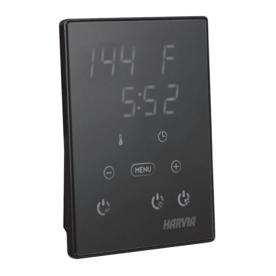
HARVIA XENIO
CX30-U1-U3 / CX45-U1-U3
CX30-U1-U3-XW (WiFi) / CX45-U1-U3-XW (WiFi)
Instructions for Installation and Use of Control Unit
Instructions d'installation et d'utilisation du centre de contrôle
ETL LISTED
Conforms to
UL 60730-1
UL 60730-2-7
UL 60730-2-9
Certified to
CSA E60730-1
CSA E60730-2-7
CSA E60730-2-9
01112021/Y05-0655
HARVIA XENIO
CX004WIFI
Publicité

Manuels Connexes pour Harvia CX30-U1-U3-XW


Sommaire des Matières pour Harvia CX30-U1-U3-XW
- Page 1 HARVIA XENIO CX30-U1-U3 / CX45-U1-U3 CX30-U1-U3-XW (WiFi) / CX45-U1-U3-XW (WiFi) Instructions for Installation and Use of Control Unit Instructions d'installation et d'utilisation du centre de contrôle HARVIA XENIO CX004WIFI ETL LISTED Conforms to UL 60730-1 UL 60730-2-7 UL 60730-2-9 Certified to...
- Page 2 à la personne Congratulations on making an excellent choice and chargée de leur maintenance. Félicitations pour cet choosing a Harvia control unit! excellent choix ! HARVIA XENIO CONTROL UNIT CENTRE DE CONTRÔLE HARVIA XENIO...
- Page 3 1. HARVIA XENIO 1.1. General 1.1. Généralités The Harvia Xenio control unit consists of a control Le centre de contrôle Harvia Xenio se compose d’un panel, a power unit and a sensor. See Figure 1. panneau de commande, d’un bloc d’alimentation et The control unit regulates the temperature d’un capteur de température.
- Page 4 1.3. Troubleshooting 1.3. Dépannage If an error occurs, the power to the heater will be Si une erreur se produit, la poêle sera mis hors ten- cut off and the control panel will show an error sion et le tableau de commande affichera un mes- message ”E (number)”, which helps troubleshooting sage d’erreur «...
- Page 5 2. INSTRUCTIONS FOR USE 2. MODE D’EMPLOI 2.1. Using the Heater 2.1. Utiliser le poêle NOTE! CX004WIFI REMARQUE CX004WIFI CX30-U1-U3-XW CX30-U1-U3-XW (WiFi) (WiFi) CX45-U1-U3-XW CX45-U1-U3-XW (WiFi) (WiFi) » See Xenio Wifi Instructions Xenio Wifi Instructions Voir » for Installation and Use d’installation et d’utilisation...
- Page 6 2.2.3. Safety switch 2.2.3. Commutateur de sécurité Safety switch refers to e.g. Harvia SFE, a safety Parmi les commutateurs de sécurité figurent par device installed above or integrated to the heater, exemple le Harvia SFE, un dispositif de sécurité...
- Page 7 BASIC SETTINGS/REGLAGES DE BASE Basic mode (heater on) Mode basique (poêle allumé) The top row shows the temperature in the La ligne supérieure montre la température du sauna room. The bottom row shows the sauna. La ligne inférieure montre la durée de remaining on time.
- Page 8 ADDITIONAL SETTINGS/AUTRES REGLAGES Control unit standby Veille du centre de contrôle Open the settings menu by simultaneously Ouvrez le menu de réglages en appuyant pressing the locations of the buttons –, simultanément sur les boutons –, MENU et +. MENU and +. Press for 5 seconds. Maintenez la pression pendant 5 secondes.
- Page 9 IPX4 CERTIFIED TO HL(S)11U3(Q) 10,5 kW B1 (default/défaut), B2, B3, B4, B5 CAN/CSA STD HARVIA OY, FINLAND 3159549 E60335-2-53-05 *Q = includes built-in contactor / contient le contacteur integré C1, C2, C3, C4, C5 D1, D2, D3, D4, D5 E1, E2, E3, E4, E5, E6 Heater grade Classe du poêle...
- Page 10 3. INSTRUCTIONS FOR INSTALLATION 3. INSTRUCTIONS D’INSTALLATION The electrical connections of the control unit may Les connexions électriques du centre de contrôle peu- only be made by a licensed professional electrician vent uniquement être effectuées par un électricien pro- and in accordance with the current regulations. fessionnel agréé...
- Page 11 ft (50 cm) away from the heater and at a maximum sauna, il doit être installé à au moins 1,5 pied (50 height of one metre from the floor. Figure 4. cm) du poêle et à une hauteur maximum d’un mètre Conductor tubing (ø...
- Page 15 Tableau 2. Puissances nominales max. du poêle et taille de câble d’alimentation min. 3.2.2. Instructions for Installation 3.2.2. Instructions d’installation The power unit of CX30-U1-U3/ CX30-U1-U3-XW Le bloc d’alimentation de la CX30-U1-U3/ CX30- (WiFi) and CX45-U1-U3 / CX45-U1-U3-XW (WiFi) U1-U3-XW (WiFi) et CX45-U1-U3 / CX45-U1- is controlled by control panel Xenio.
- Page 16 3 15/16” 3 15/16” (100 mm) (100 mm) Sensor Capteur Sensor Capteur A min. A min. A min. A min. A / D = Safety distance of heater (Check from heater manual)/ Distance de sécurité du poêle (Vérifier dans le manuel du poêle) Figure 7.
- Page 17 3 15/16” (100 mm) Sensor Capteur A / D = Safety distance of heater (Check from heater manual)/ Distance de sécurité du poêle (Vérifier dans le manuel du poêle) Figure 8. The place of the temperature sensor of Figure 9. Sensor’s minimum distance from an air vent the control unit in connection with wall- Figure 9.
- Page 18 Temperature sensor Capteur de température WX232 Circuit board Circuit imprimé WX361 6a Contactor 30 A (CX30-U1-U3, CX30-U1-U3-XW) Contactor 30 A (CX30-U1-U3, CX30-U1-U3-XW) ZSK-778 6b Contactor 45 A (CX45-U1-U3, CX45-U1-U3-XW) Contactor 45 A (CX45-U1-U3, CX45-U1-U3-XW) ZSL-940 Data cable 20 m (accessory) Câble de rallonge 20 m (accessoire)
- Page 19 15 jours suivant l’achat. La garantie s’applique uniquement à la première ins- tallation du produit et à l’acheteur d’origine. Harvia control unit model/ Modèle de centre de contrôle Harvia Model number/Numéro de modèle Date of purchase/Date d’achat Original purchaser/Acheteur d’origine Address/Adresse Purchased from/Acheté...