PR electronics 9410 Mode D'emploi
Masquer les pouces
Voir aussi pour 9410:
- Mode d'emploi (2 pages) ,
- Manuel de produit (29 pages) ,
- Mode d'emploi (61 pages)

Manuels Connexes pour PR electronics 9410


Sommaire des Matières pour PR electronics 9410
- Page 1 9 4 1 0 C o n t r o l e u r d ’ a l i m e n t a t i o n N o 9 4 1 0 V 1 0 1 - F R V e r s i o n d e p r o d u i t : 9 4 1 0 - 0 0 1...
- Page 2 PR electronics A/S tilbyder et bredt program af analoge og digitale signalbehandlingsmoduler til industriel automation. Programmet består af Isolatorer, Displays, Ex-barrierer, Temperaturtransmittere, Universaltransmittere mfl. Vi har modulerne, du kan stole på i selv barske miljøer med elektrisk støj, vibrationer og temperaturudsving, og alle produkter opfylder de strengeste internationale standarder.
-
Page 3: Table Des Matières
Référence de commande ..............Spécifications électriques ..............Connexions ....................Schéma de principe ................10 Appendix ....................11 IECEx Installation Drawing............. 12 ATEX Installation Drawing ............. 15 FM Installation Drawing ..............18 INMETRO Installation Drawing ............. 21 9410 - Product Version 9410-001... -
Page 4: Avertissement
électrostatiques (ESD) : montage général, raccordement et débranchement de fils et recherche de pannes sur le module. seule pR electronics saRl est autorisée à réparer le module et à remplacer les dis joncteurs. signiFiCation DEs symbolEs triangle avec point d’exclamation : Attention ! Lire ce manuel avant... -
Page 5: Environnement
L’interupteur doit être à proximité du module et facile d’accès. Ce bouton doit être étiqueté avec la mention : peut couper la tension du module. L’année de production est définie par les deux premiers chiffres du numéro de série. 9410 - Product Version 9410-001... -
Page 6: Limitation De Responsabilite
PR electronics SARL, même si cette dernière figure dans l’accord de vente conclu. DEmontagE DU systEmE 9000 Figure 1 : Débloquez le verrou inférieur pour dégager le module du rail DIN. 9410 - Product Version 9410-001... -
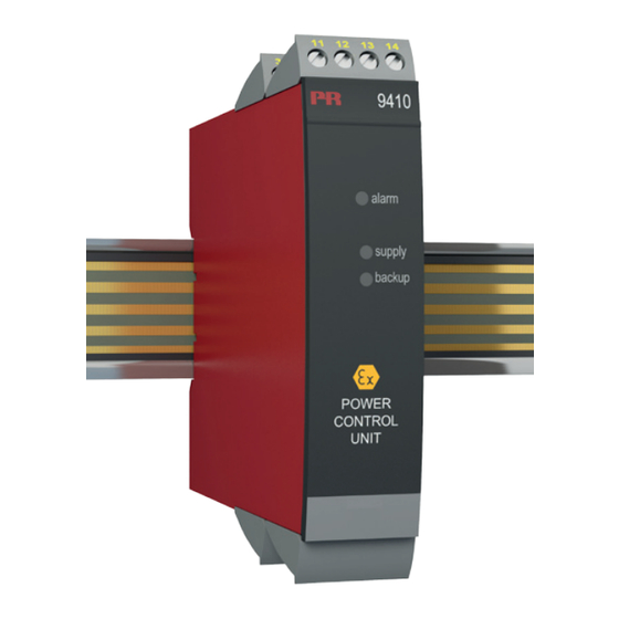
Page 7: Controleur D'alimentation 9410
• Doit être monté sur le power rail, PR type 9400 application et options avancées • Le 9410 détecte des erreurs des modules montés sur le rail d’alimentation et transmet une alarme collective au système de contrôle par le relais d’état interne. -
Page 8: Applications
Alim. de secours, +24 Vcc Alim. de secours, masse Si l’alimentation de secours n’est pas utilisé : Placer un shunt entre les bornes 32 et 33. Power rail Zone 2 / FM Cl. 1, div. 2 ou zone non-dangereuse 9410 - Product Version 9410-001... -
Page 9: Référence De Commande
Ondulation de sortie ..........Egale à l’ondulation d’entrée Relais d’état en zone non-dangereuse : Tension max............... 250 / 30 Vcc Courant max............... 2 Aca / 2 Acc Puissance ca max............ 500 VA / 60 W 9410 - Product Version 9410-001... - Page 10 Det Norske Veritas, Ships & Offshore ..... Stand. f. Certific. No. 2.4 s.i. / Ex : ATEX 94/9/CE ............KEMA 07ATEX0152 X IECEx ................IECEx KEM 08.0025X c FM us ................. 3034431-C INMETRO ..............NCC 12.1308 X 9410 - Product Version 9410-001...
-
Page 11: Connexions
: Placer un shunt entre les bornes 32 et 33. sorties : Alimentation pour Relais d’état le power rail 11 12 13 14 91 92 93 94 95 N.O. N.C. Masse +24 V 9410 - Product Version 9410-001... -
Page 12: Schéma De Principe
DE pRinCipE Rail, masse Rail, +24 V Rail, état 9410 - Product Version 9410-001... -
Page 13: Appendix
Fm installation drawing inmEtRo installation drawing 9410 - Product Version 9410-001... -
Page 14: Iecex Installation Drawing
IECEx Installation drawing 9410 For safe installation of 9410 the following must be observed. The module shall only be Installed by qualified personnel who are familiar with the national and international laws, directives and standards that apply to this area. - Page 15 Use 9400 Cover to prevent open Power Rail from unintentional short circuit. Power is supplied to the Power Rail from two 9410 Power Redundant 9410 Power Control with Backup. Control Modules. Both modules have connections for Normal Supply and Backup Supply. Revision date:...
- Page 16 LERBAKKEN 10, 8410 RØNDE DENMARK Installation notes: General The 9410 must be supplied from a Power Source with Double or Reinforced insulation to Mains. For installation in Zone 2 The 9410 Power Control Unit and 9400 Power Rail must be installed in an outer enclosure having an IP protection of at least IP54, conforming to the requirements of explosion protection Ex-n or Ex-e.
-
Page 17: Atex Installation Drawing
ATEX Installation drawing 9410 For safe installation of 9410 the following must be observed. The module shall only be Installed by qualified personnel who are familiar with the national and international laws, directives and standards that apply to this area. - Page 18 Use 9400 Cover to prevent open Power Rail from unintentional short circuit. Power is supplied to the Power Rail from two 9410 Power Redundant 9410 Power Control with Backup. Control Modules. Both modules have connections for Normal Supply and Backup Supply. Revision date:...
- Page 19 9420 Power Supply and other modules. General The 9410 must be supplied from a Power Source with Double or Reinforced insulation to Mains. Alternatively use PR9420 Power Supply for installation inside or outside Zone2. For installation in Zone 2...
-
Page 20: Fm Installation Drawing
FM Installation drawing 9410 Power Control Unit For safe installation of 9410 the following must be observed. The module shall only be Installed by qualified personnel who are familiar with the national and international laws, directives and standards that apply to this area. - Page 21 Use 9400 Cover to prevent open Power Rail from unintentional short circuit. Power is supplied to the Power Rail from two 9410 Power Redundant 9410 Power Control with Backup. Control Modules. Both modules have connections for Normal Supply and Backup Supply. Revision date:...
- Page 22 WARNING: Do not install or remove modules from the Power Rail and do not remove connectors from the module unless Area is known to be Non Hazardous. Revision date: Version Revision Prepared by: Page: 2009-03-30 V2 R3 9410 - Product Version 9410-001...
- Page 23 INMETRO Desenhos para Instalação 9410 Para instalação segura do 9410 o manual seguinte deve ser observado. O módulo deve ser instalado somente por profissionais qualificados que estão familiarizados com as leis nacionais e internacionais, diretrizes e normas que se aplicam a esta área.
- Page 24 A energia é fornecida ao barramento de alimentação de dois módulos de controle de energia 9410. Ambos os módulos têm conexões para a fonte de alimentação normal e a fonte reserva. Controle de Potencia 9410 redundante com reserva Revision date: Version Revision Prepared by: Page:...
- Page 25 LERBAKKEN 10, 8410 RØNDE DENMARK Notas para Instalação: Geral O 9410 deve ser energizado por uma fonte de alimentação com isolamento duplo ou reforçado vindo da rede elétrica. Para instalação em Zona 2 O equipamento deve ser instalado dentro de um invólucro certificado conforme as normas da série ABNT NBR IEC 60079 que forneça no mínimo grau de...
- Page 26 Displays Displays Programmable displays with a wide Programmable displays with a wide selection of inputs and outputs for display of temperature, selection of inputs and outputs for display of temperature, volume and weight, etc. Feature linearisation, scaling, and volume and weight, etc. Feature linearisation, scaling, and difference measurement functions for programming via difference measurement functions for programming via PReset software.
- Page 27 www.prelectronics.se sales@prelectronics.se www.prelectronics.co.uk sales@prelectronics.co.uk www.prelectronics.com sales@prelectronics.com www.prelectronics.cn sales@prelectronics.cn head office Denmark www.prelectronics.com PR electronics A/S sales@prelectronics.dk Lerbakken 10 tel. +45 86 37 26 77 DK-8410 Rønde fax +45 86 37 30 85...