Table des Matières
Publicité
Les langues disponibles
Les langues disponibles
Liens rapides
IT
EN
FR
NL
ES
MANUALE
TECHNICAL
MANUEL
TECHNISCHE
MANUAL
TECNICO
MANUAL
TECHNIQUE
HANDLEIDING
TÉCNICO
41LED032
Manuale tecnico modulo 32 uscite Art.41LED032
Technical manual 32 outputs module Art.41LED032
Manuel technique module avec 32 sorties Art.41LED032
Passion.Technology. Design.
Technische handleiding module met 32 uitgangen Art.41LED032
Manual técnico módulo con 32 salidas Art.41LED032
Publicité
Table des Matières

Manuels Connexes pour Comelit 41LED032


Sommaire des Matières pour Comelit 41LED032
- Page 1 MANUAL TECHNIQUE HANDLEIDING TÉCNICO 41LED032 Manuale tecnico modulo 32 uscite Art.41LED032 Technical manual 32 outputs module Art.41LED032 Manuel technique module avec 32 sorties Art.41LED032 Passion.Technology. Design. Technische handleiding module met 32 uitgangen Art.41LED032 Manual técnico módulo con 32 salidas Art.41LED032...
-
Page 2: Istruzioni Per L'installazione
Tipi di cablaggio Le uscite LED del modulo 41LED032 possono essere cablate come tipo di circuito ad Anodo Comune (CA) o Catodo Comune (CC). Il tipo di circuito si seleziona tramite il jumper “CA/CC” presente sulla scheda elettronica. Il tipo di circuito “Anodo Comune” si seleziona rimuovendo il jumper;... -
Page 3: Caratteristiche Tecniche
* Commutazione da chiuso ad aperto ** Commutazione da aperto a chiuso Nota: La lunghezza massima del cavo dal modulo 41LED032 ai LED del pannello sinottico/ripetitore collegato deve essere di 3 m. CONNETTORI A SPINA Il modulo 41LED032 viene fornito con un set di connettori a spina per l’installazione rapida dei fili, montati sui morsetti della scheda elettronica. -
Page 4: Componenti Del Modulo
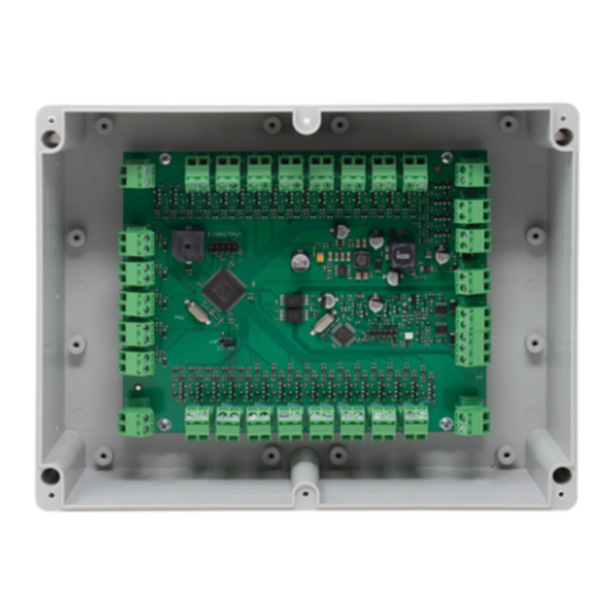
COMPONENTI DEL MODULO 41LED032 Uscite LED da 1 a 16* Uscite LED da 17 a 32* Morsetti “GND” per realizzare il tipo di circuito a catodo comune. Morsetti “+12V” per realizzare il tipo di circuito ad anodo comune. Morsetti di collegamento loop. -
Page 5: Schemi Di Collegamento
PROGRAMMAZIONE INDIRIZZO Utilizzare il cavo con morsetto a 5 pin. SCHEMI DI COLLEGAMENTO a) Cablaggio delle uscite LED Tipo di circuito ad anodo comune; jumper “CA/CC” rimosso, Ri = 1 kΩ o Ri = 0 kΩ. Tipo di circuito a catodo comune; jumper “CA/CC” inserito, Ri = 1 kΩ o Ri = 0 kΩ. Spegnere il modulo prima di inserire/rimuovere il jumper "CA/CC"... -
Page 6: Installation Instructions
Operation Access Levels of the Inputs The 41LED032 module is provided also with 4 special inputs for user operation, organized in 2 access levels. The Level 1 is giving access for operation with the module itself: Silencing of the internal buzzer (via the “Sil. BUZZ” input) and testing the operation of LED outputs and buzzer (via the “TEST”... -
Page 7: Technical Specifications
* Switches from closed to open ** Switches from open to closed Note: The maximum cable length from the 41LED032 module to the LEDs in the connected mimic/repeater panel must be up to 3m. PLUG CONNECTORS The 41LED032 module is delivered with a set of plug connectors for quick wire installation, mounted to the terminals on the PCB. -
Page 8: Module Components
MODULE COMPONENTS 41LED032 LED Outputs from 1 to 16* LED Outputs from 17 to 32* “GND” Terminals for realizing common-cathode circuit type. “+12V” Terminals for realizing common-anode circuit type. Loop connection terminals. Terminals for connection of external power supply 12-24 VDC. -
Page 9: Connection Diagrams
ADDRESS PROGRAMMING Use the cable with 5-pin terminal. CONNECTION DIAGRAMS a) Wiring of LED Outputs Common-anode circuit type; “CA/CC” jumper is removed, Ri = 1kΩ or Ri = 0kΩ. Common-cathode circuit type; “CA/CC” jumper is set, Ri = 1kΩ or Ri = 0kΩ. Power off the module before setting/removing the “CA/CC”... - Page 10 Types de câblage Les sorties LED du module 41LED032 peuvent être câblées en tant que circuit à anode commune (CA) ou à cathode commune (CC). Le type de circuit est réglé par le cavalier « CA/CC » sur la carte électronique. Le type de circuit « anode commune » est sélectionné...
-
Page 11: Spécifications Techniques
Remarque: * Passe de fermé à ouvert ** Passe de ouvert à fermé Remarque : La longueur maximale du câble reliant le module 41LED032 aux LED du panneau synoptique/répéteur connecté doit être de 3 m. CONNECTEURS À FICHE Le module 41LED032 est livré avec un jeu de connecteurs pour une installation rapide des fils, montés sur les bornes de la carte électronique. -
Page 12: Composants Du Module
COMPOSANTS DU MODULE 41LED032 Sorties LED de 1 à 16* Sorties LED de 17 à 32* Bornes “GND” pour la réalisation d’un circuit à cathode commune. Bornes “+12V” pour la réalisation d’un circuit à anode commune. Bornes de connexion en boucle. -
Page 13: Programmation Des Adresses
PROGRAMMATION DES ADRESSES Utiliser le câble avec une borne à 5 broches SCHÉMAS DE CONNEXION a) Câblage des sorties LED Type de circuit à anode commune ; le cavalier « CA/CC » est retiré, Ri = 1 kΩ ou Ri = 0 kΩ. Type de circuit à... -
Page 14: Installatie-Instructies
Bediening toegangsniveaus van de ingangen De 41LED032-module is ook voorzien van 4 speciale ingangen voor bediening door de gebruiker, georganiseerd in 2 toegangsniveaus. Niveau 1 geeft toegang voor bediening met de module zelf: Uitzetten van de interne zoemer (via de “Sil. BUZZ”-ingang) en testen van de bediening van de LED-uitgangen en zoemer (via de “TEST”-ingang). -
Page 15: Technische Specificaties
Opmerkingen: * Schakelt van gesloten naar open ** Schakelt van open naar gesloten Opmerking: De maximale kabellengte van de 41LED032-module naar de leds in het aangesloten nabootsings- / herhaalpaneel moet maximaal 3 meter zijn. STEKKERCONNECTOREN De 41LED032-module wordt geleverd met een set stekkerconnectoren een voor snelle draadmontage, gemonteerd op de klemmen op de printplaat. - Page 16 MODULE-ONDERDELEN 41LED032 LED-uitgangen van 1 tot 16* LED-uitgangen van 17 tot 32* “GND”-klemmen voor het realiseren van een gemeenschappelijke kathode-schakeling. “+12V”-klemmen voor het realiseren van een gemeenschappelijke anode-schakeling. Lusaansluitklemmen. Klemmen voor aansluiting externe voeding 12-24 VDC. Speciale LED-uitgangen: ◊ “FIRE” - Herhalen van de LED-indicatie voor een brandalarmgebeurtenis van het brandmeldpaneel**.
- Page 17 PROGRAMMEREN ADRESSEN Gebruik de kabel met de klem met 5 pinnen. AANSLUITSCHEMA’S a) Bedrading van LED-uitgangen Gemeenschappelijke anode-schakeling; “CA/CC”-jumper is verwijderd, Ri = 1kΩ of Ri = 0kΩ. Gemeenschappelijke kathode-schakeling; “CA/CC”-jumper is geplaatst, Ri = 1kΩ of Ri = 0kΩ Schakel de module uit voordat u de “CA/CC”-jumper instelt/verwijdert voor de selectie van het type schakeling voor de bedrading van de LED-uitgangen! Het plaatsen/verwijderen van de jumper, wanneer de stroom is ingeschakeld, verandert het type schakeling niet! b) Aansluiting externe voeding...
- Page 18 Tipos de cable Las salidas LED del módulo 41LED032 se pueden cablear como circuito de tipo nodo común (CA) o cátodo común (CC). El tipo de circuito se ajusta mediante el puente «CA/CC» en la placa de circuito impreso. El tipo de circuito «Nodo común» se selecciona cuando se retira el puente;...
-
Page 19: Especificaciones Técnicas
Notas: * Cambia de cerrado a abierto ** Cambia de abierto a cerrado Nota: La longitud máxima del cable desde el módulo 41LED032 hasta los ledes del panel sinóptico/repetidor conectado debe ser de hasta 3 m. CONECTORES DE ENCHUFE El módulo 41LED032 se entrega con un juego de conectores para la instalación rápida de los cables, montados en los terminales de la placa de circuito impreso. -
Page 20: Componentes Del Módulo
COMPONENTES DEL MÓDULO 41LED032 Salidas LED de 1 a 16* Salidas LED de 17 a 32* Bornes «GND» para realizar el tipo de circuito de cátodo común. Bornes «+12 V» para realizar el tipo de circuito de ánodo común. Bornes de conexión de la instalación: Bornes para la conexión de una fuente de alimentación externa 12-24 VCC. -
Page 21: Esquemas De Conexión
PROGRAMACIÓN DE LA DIRECCIÓN Utilice el cable con terminal de 5 pines. ESQUEMAS DE CONEXIÓN a) Cableado de las salidas LED Tipo de circuito de ánodo común; puente «CA/CC» retirado, Ri = 1 kΩ o Ri = 0 kΩ. Tipo de circuito de cátodo común; el puente «CA/CC» colocado , Ri = 1 kΩ o Ri = 0 kΩ. Apague el módulo antes de ajustar/retirar el puente «CA/CC»... - Page 24 C E R T I F I E D M A N A G E M E N T S Y S T E M S EN 54-18:2005 EN 54-18:2005/AC:2007 1293 w w w . c o m e l i t g r o u p . c o m EN 54-17:2005 1ª...