Page 1
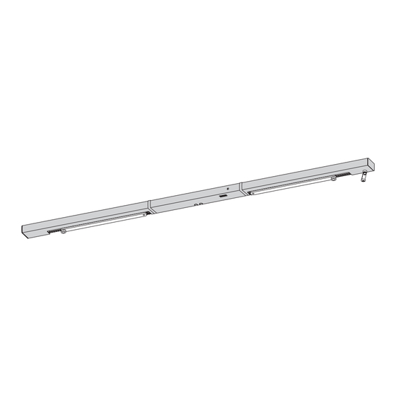
GEZE TS 5000 R-ISM BG Gleitschiene für Bandgegenseite mit integrierter Schließfolgeregelung, Rauchschalter und elektrischer Feststellung Guide rail for push side with integrated closing sequence control, smoke detector and electrical hold-open device Bras à coulisse avec regulation intégrée de fermeture en cascade, commutateur de fumée et arrêt électrique pour montage...
Page 2
Zu diesem Dokument TS 5000 R-ISM BG Zu diesem Dokument Diese Anleitung beschreibt die Montage und den Anschluss sowie die Inbetriebnahme der GEZE TS 5000 R-ISM BG Gleitschiene. Produktbeschreibung Diese Gleitschiene ist für die Montage an zweiflügeligen Feuer- und Rauchschutztüren zugelassen. Die Anlage enthält elektrische Feststellungen für beide Türflügel, die von einer integrierten Rauchschalterzentrale gesteuert...
Page 3
TS 5000 R-ISM BG Lieferumfang Lieferumfang Abb.: 5.1 Gangflügel Gleithebel Rauchschaltergehäuse Standflügel Netzteil mit Aufnahme Resettaste ISM Gleitschiene Gangflügel Endkappe Gleitstein ISM Gleitschiene Standflügel Blende Gangflügel Drahtseilumlenkung Rauchschalter (verpackt) Blende Standflügel Auslösehebel Elektrische-Feststellung GF Mittelblende Schrauben, Anschlagschablone Elektrische-Feststellung SF Sichtkappe und Zubehörbeutel...
Page 4
Distanz zwischen Oberkante Gleitschiene und Decke/Sturz von mindestens 10 mm >10 mm nicht unterschritten werden! Je nach Feststellanlage beachten Sie bitte auch das Dokument „Anleitung zur Mon- tage, Inbetriebnahme, Bedienung und Wartung der GEZE Feststellanlage FA GC“. Abb.: 6.1.2 Gleitschiene und Netzteil montieren M5x45...
Page 5
TS 5000 R-ISM BG Montage, Befestigung Bei Aufputzzuführung für das 230-V-Kabel einen Kabelschutz verwenden. Die aus der Wand stehenden Kabel für 230 V und für Zusatzanschlüsse durch die entsprechenden Öffnungen des Rauchschaltergehäuses führen! M5x45/5x55 Abb.: 6.3.1 230 V Netzkabel durch das Rauchschaltergehäuse führen und auf ca. 80 mm ablängen (1.).
Page 6
Montage, Befestigung TS 5000 R-ISM BG Kabel von Netzteil und Rauchschalter verlegen Abb.: 6.6.1 24 V Ausgangskabel vom Netzteil am Gangflügel in das Innere des Rauchschaltergehäuses verlegen (6.). Rot =’+’ Weiß = ’–’ . Abb.: 6.6.2 Kabel 24 V der elektrischen Feststellung vom Gehäuseinneren zur Anschlussklemme führen (1.).
Page 7
TS 5000 R-ISM BG Montage, Befestigung Anschlagschrauben einschrauben (6.). Spannteil wieder entspannen (7.) Spannschraube einschrauben (Kontermutter noch nicht anziehen!). Drahtseil auf 30–50 mm Überstand zur Außenkante Gleitschiene kürzen (8.). M3x10 M3x10 M6x14 SW 5 Abb.: 6.7.2 Gleithebel am Standflügel montieren und mit Gleitstein verbinden Im Lieferzustand behindert die Türkante das korrekte Aufsetzen des Gleithebels auf den Schließer.
Page 8
Montage, Befestigung TS 5000 R-ISM BG Auslöser und Sperre einstellen Achten Sie darauf, dass das Drahtseil nicht eingeklemmt wird. Bei korrekter Einstellung müssen die Scheibe und die Kerbe in einer Flucht liegen. Abstand zwischen Scheibe und Kerbe messen (1.). Drahtseil um “X” spannen (2.).
Page 9
TS 5000 R-ISM BG Montage, Befestigung Anschlagstange darf nicht unter den Mitnehmer kippen. Anschlagstange herausziehen (3.). Abstand Kante-Sperre und Anschlag: ca. 30 mm Gangflügeltür schließen (4.). Anschlagstange für Funktionssicherung der Schließfolgeregelung ist positioniert. Gangflügeltür öffnen (5.). Schrauben der Anschlagstange festziehen (6.).
Page 10
Erstinbetriebnahme TS 5000 R-ISM BG Erstinbetriebnahme VORSICHT! Der Einbau des Rauchschalters darf erst kurz vor Inbetriebnahme erfolgen um unnötige Verschmutzungen zu vermeiden. Bei vorzeitigem Einbau besteht die Gefahr, dass der Rauchschalter durch den Baustaub verschmutzt wird. Dadurch kann die Lebensdauer des Rauchschalters erheblich verkürzt werden! 7.
Page 11
TS 5000 R-ISM BG Erstinbetriebnahme Einstellen der elektrischen Feststellungen Darstellung Gangflügel. Türflügel auf den gewünschten Feststellwinkel öffnen und festsetzen (1.). Kabelschutzfolien aus der Gleitschiene entfernen (2.). Klemmschrauben der elektrischen Feststellung lösen (3.). Elektrische Feststellung verschieben, bis Rastkeil am Gleitstein anliegt (4.).
Page 12
Nach dem betriebsfertigen Einbau der Anlage ist am Verwendungsort deren einwandfreie Funktion und vor- schriftsmäßige Installation durch eine Abnahmeprüfung festzustellen. Abnahmeprüfung durch autorisiertes Fachpersonal siehe Dokument „Anleitung zur Montage, Inbetriebnahme, Bedienung und Wartung der GEZE Fest- stellanlage FA GC“. Wartung, Pflege, Reparatur Die Einbaufirma muss den Betreiber der Anlage auf diesen Teil der Montageanleitung aufmerksam machen, und die- se sowie die Benutzerinformation (Beipackzettel zum Türschließer) dem Betreiber aushändigen.
Page 13
If a double leaf smoke or fire protection door can be opened via the passive leaf, without opening the active leaf up to the minimal waiting position of the sequence control, a preferably adjustable carry bar such as the GEZE CBflex must be used to ensure the functionality of the door sequence control unit.
Page 14
Scope of delivery TS 5000 R-ISM BG Scope of delivery Fig.: 5.1 Moving leaf Wire cable for trigger Protective cap Fixed leaf Trigger Foam lining ISM Moving-leaf guide rail Sliding lever Smoke switch housing ISM Fixed-leaf guide rail Power pack with mounting...
Page 15
Electric wiring must only be carried out by professional electricians. Operating voltage: 230 V AC +10% / -15%, Interrupt power supply! The GEZE hold-open devices FA GC are appliances of the protection class II. Protection class IP 20, only for dry rooms. Ambient temperature -5 °C to 50 °C.
Page 16
Mounting and securing TS 5000 R-ISM BG Use cable protection for the 230 V cable when leading through plaster. Insert the 230 V cable/cable for additional connections protruding from the wall through the respective openings of the smoke detector housing! M5x45/5x55 Fig.: 6.3.1...
Page 17
Mounting and securing TS 5000 R-ISM BG Connecting cable from power pack and cable from smoke detector Fig.: 6.6.1 Place 24 V output cable from power pack on moving leaf into the inside of the smoke switch housing (6.). Red =’+’...
Page 18
Mounting and securing TS 5000 R-ISM BG Screw in stop screws (6.). Loosen clamping part again (7.) screw in set screw (do not tighten lock nut yet!). Shorten wire cable to an excess of 30-50 mm to outer edge of guide rail (8.).
Page 19
Mounting and securing TS 5000 R-ISM BG Adjusting trigger and block Ensure that the wire cable is not pinched. When adjusted correctly, the disc and the notch must be aligned. Measure distance between disc and notch (1.). Tension wire cable by “X”...
Page 20
Mounting and securing TS 5000 R-ISM BG Stop rod may not pass under driver. Pull out stop rod (3.). Distance between edge block and stop is approx. 30 mm Close moving leaf (4.). Stop rod for function safeguard of the integrated closing sequence control is in position.
Page 21
Plug in 24 V cable of the of electrical hold-open device (1) and the power pack (2). Stow away the excess cable into the power pack housing. For additional connections, see the separate document “Instructions for Installation, Commissioning, Operation and Maintenance of the GEZE Hold-Open Device FA GC”. Fig.: 7.2.2 GB 10...
Page 22
Initial operation TS 5000 R-ISM BG Adjusting electrical hold-open device Moving leaf is shown. Open door leaf to desired hold-open angle and fix it there (1.). Remove cable protection foils from guide (2.). Loosen clamping screws of electrical hold-open device (3.).
Page 23
The installing company must alert the operator of the system to this part of the mounting instructions and hand it over to the operator together with the user information (see ‚GEZE user information for door closer‘). Regular servi- cing has to be carried out. For more information on this, please observe the document “Instructions for Installation, Commissioning, Operation and Maintenance of the GEZE Hold-Open Device FA GC”.
Page 24
TS 5000 R-ISM BG Concernant le présent document Le présent manuel décrit le montage et la mise en service ainsi que le raccordement du bras à coulisse GEZE TS 5000 R-ISM BG. Description du produit Cette glissière est homologuée pour être montée sur des portes anti-feu et anti-fumée à vantail unique. L‘installation comprend des arrêts électriques pour les deux battants de porte, qui sont commandés par un commutateur de fumée, ainsi qu‘une régu-...
Page 25
Contenu de la livraison TS 5000 R-ISM BG Contenu de la livraison Fig.: 5.1 Battant mobile déclenchement Capuchon de protection Battant fixe Dispositif de déclenchement Garniture en mousse ISM Bras à coulisse du bat- Levier coulissant Boîtier de commutateur de tant mobile Bloc d‘alimentation avec...
Page 26
Tension de service: 230 V CA +10% / -15%, Interrompre l‘alimentation en courant! Les dispositifs de blocage FA GC de GEZE sont des appareils relevant de la classe de protection II. Type de protection IP 20, pour locaux secs uniquement. Température ambiante -5 °C à 50 °C.
Page 27
Montage, fixation TS 5000 R-ISM BG Dans le cas d‘une alimentation électrique apparente, utiliser une protection pour le câble d‘alimentation 230 V. Faire passer les câbles sortant du mur pour l‘alimentation 230 V et les raccordements supplémentaires à travers les ouvertures correspondantes du boîtier du commutateur de fumée.
Page 28
Montage, fixation TS 5000 R-ISM BG Poser le câble de l‘alimentation électrique et le câble du commutateur de fumée Fig.: 6.6.1 Disposer le câble de sortie de 24 V à l‘intérieur du boîtier de commutateur de fumée (6.). Rouge =’+’...
Page 29
Montage, fixation TS 5000 R-ISM BG Desserrer le contre-écrou du serre-câble (7). Visser le tendeur (ne pas serrer immédiatement le contre-écrou). Raccourcir le câble à 30-50 mm en saillie par rapport à l‘arête extérieure du bras à coulisse (8.). M3x10...
Page 30
Montage, fixation TS 5000 R-ISM BG Régler le dispositif de déclenchement et le blocage Veillez à ce que le câble métallique ne soit pas coincé. Pour un réglage correct, la plaque et l‘encoche doivent être alignées. Mesurer la distance entre la plaque et l‘encoche...
Page 31
Montage, fixation TS 5000 R-ISM BG La tige de butée ne peut pas être en dessous de l‘entraîneur. Extraire la tige de butée (3.). Distance arête-blocage et butée env. 30 mm. Fermer le battant mobile (4.). La tige de butée pour la protection fonctionnel de la régulation de fermeture en cascade est positionnée.
Page 32
Ranger le câble excédentaire dans le logement du bloc d‘alimentation. Raccords supplémentaires, observer les indications figurant dans le document distinct « Instructions de montage, mise en service, utilisation et maintenance de l’installation de blocage GEZE FA GC ». Fig.: 7.2.2...
Page 33
Première mise en service TS 5000 R-ISM BG Réglage des arrêts électriques Représentation du battant mobile. Ouvrir le battant de porte à l‘angle d‘arrêt souhaité et le bloquer (1.). Enlever les films protecteurs de câbles du bras à coulisse (2.).
Page 34
à l‘utilisateur (notice sur le ferme-porte). Il faut pro- céder à une maintenance régulière. Pour de plus amples informations, veuillez observer les indications figurant dans le document « Instructions de montage, mise en service, utilisation et maintenance de l’installation de blocage GEZE FA GC ».