Publicité
Liens rapides
FRANÇAIS
Relais amplificateur série 9270
1. Consignes de sécurité
1.1 Instructions d'installation
• L'appareil est considéré comme un équipement électrique associé (catégorie 1) de la classe de protection
antidéflagrante « à sécurité intrinsèque » et est adapté à une installation en tant qu'appareil de catégorie 3
dans des atmosphères explosibles de zone 2. Il répond aux exigences des normes EN 60079-
0:2012+A11:2013, EN 60079-11:2012 et EN 60079-15:2010 ou CEI 60079-0 Ed. 6.0, CEI 60079-11
Ed. 6.0 et CEI 60079-15 Ed. 4.0.
• L'installation, l'utilisation et la maintenance doivent être confiées à un personnel spécialisé dûment qualifié
en électrotechnique. Respecter les instructions d'installation mentionnées. Lors de mise en place et de l'ex-
ploitation, respecter les dispositions et les normes de sécurité en vigueur (et les normes de sécurité natio-
nales), ainsi que les règles générales relatives à la technique. Les caractéristiques techniques de sécurité
se trouvent dans ce document et dans les certificats (certificat UE d'essai de type, voire autres homologa-
tions).
• L'ouverture ou la transformation de l'appareil ne sont pas admissibles. Ne procédez à aucune réparation sur
l'appareil, mais remplacez-le par un appareil équivalent. Seul le fabricant est autorisé à effectuer des répa-
rations sur l'appareil. Le fabricant n'est pas responsable des dommages résultant d'infractions à cette règle.
• L'indice de protection IP20 (CEI/EN 60529) de l'appareil est valable dans un environnement propre et sec
(degré de pollution 2, CEI/EN 60664-1). Ne jamais soumettre l'appareil à des sollicitations mécaniques et/
ou thermiques dépassant les limites indiquées.
• L'appareil est conforme répond aux règlements relatifs aux parasites (CEM) destinés au domaine industriel
(catégorie de protection A). L'utilisation dans une zone d'habitation peut créer des parasites.
1.2 Sécurité intrinsèque
• L'appareil est homologué pour les circuits à sécurité intrinsèque (Ex-i) jusqu'à la zone Ex 0 (gaz) et à la zone
EX 20 (poussière). Il convient de respecter les valeurs techniques de sécurité des équipements électriques
à sécurité intrinsèque et des câbles de connexion, lors de l'assemblage (CEI/EN 60079-14), ainsi que les
valeurs indiquées dans ces instructions d'installation et dans le certificat UE d'essai de type.
• Si des mesures doivent être effectuées du côté à sécurité intrinsèque, respecter impérativement les pres-
criptions en vigueur concernant l'interconnexion de matériel électrique à sécurité intrinsèque. Dans des cir-
cuits à sécurité intrinsèque, utiliser uniquement des appareils de mesure dûment homologués pour ceux-ci.
• Si l'appareil a été intégré dans des circuits électriques sans sécurité intrinsèque, il est interdit de l'installer
ultérieurement dans un circuit à sécurité intrinsèque. Réalisez un marquage sans ambiguïté indiquant que
l'appareil n'est pas à sécurité intrinsèque.
1.3 Installation en zone Ex (Zone 2)
• Respecter les conditions définies pour une utilisation en atmosphère explosible. Lors de l'installation, utili-
ser un boîtier adapté et homologué d'indice de protection minimum IP54 qui répond aux exigences de la
norme CEI/EN 60079-15. Respecter également les exigences de la norme CEI/EN 60079-14.
• Le raccordement et la déconnexion de câbles, ainsi que le réglage des sélecteurs de codage (DIP) en
zone 2 sont autorisés uniquement lorsque l'appareil est hors tension.
• L'encliquetage/désencliquetage sur un/du pac-Bus 9294 ou le branchement et le débranchement des
câbles en atmosphère explosible ne sont autorisés qu'en cas d'absence de tension.
• L'appareil doit être mis hors service et retiré immédiatement de la zone Ex s'il est endommagé ou s'il a été
soumis à des charges ou stocké de façon non conforme, ou s'il présente un dysfonctionnement.
1.4 Zones avec présence de poussières explosives
• L'appareil n'est pas conçu pour une utilisation en zone 22.
• Si l'appareil doit pourtant être utilisé en zone 22, il convient de l'intégrer dans un boîtier conforme à CEI/
EN 60079-31. Tenir compte des températures maximum de surface admises. Respecter les exigences de
la norme CEI/EN 60079-14.
• Procéder à l'interconnexion avec le circuit électrique à sécurité intrinsèque dans des atmosphères explo-
sibles (poussière) de zone 20, 21 ou 22 seulement si l'équipement électrique raccordé à ce circuit est ho-
mologué pour cette zone (par ex. catégorie 1D, 2D ou 3D).
1.5 Applications sécurisées (SIL)
IMPORTANT
En cas d'utilisation de l'appareil dans des applications relatives à la sécurité, respecter les
consignes du manuel de sécurité disponible à l'adresse www.r-stahl.com, car celles-ci peuvent
différer avec une fonction de sécurité.
2. Brève description
Le relais amplificateur est conçu pour le fonctionnement à sécurité intrinsèque de détecteurs de proximité (se-
lon CEI/EN 60947-5-6, NAMUR) et des contacts ou commutateurs non raccordés ou équipés d'un circuit de
résistance.
Un relais (contact inverseur) sert de sortie signal.
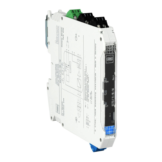
3. Eléments de commande et voyants ()
1 LED jaune « OUT »,état de commutation
2 LED rouge « LF », défaut de ligne sur câble de capteur
3 LED verte « PWR », alimentation en tension
4 Bornes de raccordement pour zone sûre (noire/verte)
5 Commutateur DIP 1 ... DIP 4
6 Bornes de raccordement pour zone Ex (sécurité intrinsèque Ex i, bleue)
4. Installation
IMPORTANT : décharge électrostatique
Prendre des mesures contre les décharges électrostatiques avant d'ouvrir le couvercle frontal.
4.1 Instructions de raccordement
EN / UL 61010-1:
AVERTISSEMENT
• Prévoir, à proximité d'un l'appareil, un commutateur/disjoncteur caractérisé comme étant le dispositif
de déconnexion de cet appareil.
• Prévoir un dispositif de protection contre les surintensités (I ≤ 16 A) dans l'installation.
• Monter l'appareil dans un boîtier adapté à indice de protection approprié selon CEI/EN 60529 pour
le protéger de tout dommage mécanique et électrique.
• Lors des travaux de maintenance, déconnecter l'appareil de toutes les sources d'énergie actives.
• Les réglages effectués sur l'appareil à l'aide du sélecteur de codage (DIP) doivent l'être lorsque l'ap-
pareil est hors tension.
• Si l'appareil n'est pas utilisé conformément à la documentation, ceci peut entraver la protection pré-
vue.
• Le boîtier de l'appareil lui confère une isolation de base vis-à-vis des appareils voisins pour 300 Veff.
Il convient d'en tenir compte lors de l'installation de plusieurs appareils côte à côte et d'installer une
isolation supplémentaire si cela est nécessaire. Si l'appareil voisin présente lui aussi une isolation de
base, aucune isolation supplémentaire n'est requise.
• Les tensions appliquées à l'entrée et au raccordement d'alimentation sont des très basses tensions
(ELV). Selon l'application, la tension de commutation présente à la sortie de relais peut être dange-
reuse (> 30 V). Dans ce cas, une isolation galvanique sûre existe en direction des autres raccorde-
ments.
L'appareil s'encliquète sur tous les rails DIN de 35 mm conformes à CEI/EN 60715. Lorsque le 9294/31-12 est
utilisé, le mettre en place d'abord pour ponter l'alimentation en tension. ()
IMPORTANT
Dans ce cas, respecter impérativement le sens d'encliquetage du module et du pac-Bus 9294 :
pied encliquetable en haut et élément enfichable à gauche.
4.2 Alimentation en tension
Il est possible de raccorder la tension d'alimentation via les bornes 5 et 6, ou via le pac-Bus 9294.
ENGLISH
Switching repeater series 9270
1. Safety notes
1.1 Installation notes
• The device is an associated apparatus (category 1) which belongs to the "Intrinsic Safety" ignition protection
class and can be installed in Ex zone 2 as a category 3 device. It meets the requirements of EN 60079-
0:2012+A11:2013, EN 60079-11:2012, EN 60079-15:2010 or IEC 60079-0 ed. 6.0, IEC 60079-11 ed. 6.0,
and IEC 60079-15 ed. 4.0.
• Installation, operation, and maintenance may only be carried out by qualified electricians. Follow the instal-
lation instructions as described. When installing and operating the device, the applicable regulations and
safety directives (including national safety directives), as well as general technical regulations, must be ob-
served. For the safety data, refer to this document and the certificates (EU examination certificate and other
approvals if appropriate).
• The device must not be opened or modified. Do not repair the device yourself, replace it with an equivalent
device. Repairs may only be carried out by the manufacturer. The manufacturer is not liable for damage re-
sulting from violation.
• The IP20 degree of protection (IEC/EN 60529) of the device is intended for use in a clean and dry environ-
ment (degree of pollution 2, IEC/EN 60664-1). Do not subject the device to mechanical and/or thermal loads
that exceed the specified limits.
• The device complies with the EMC regulations for industrial areas (EMC class A). When using the device in
residential areas, it may cause radio interference.
1.2 Intrinsic safety
• The device is approved for intrinsically safe (Ex i) circuits up to zone 0 (gas) and zone 20 (dust) in the Ex
area. The safety technology values for intrinsically safe equipment and the connecting lines must be ob-
served for the hook-up process (IEC/EC 60079-14) and the values specified in this installation note and/or
the EU examination certificate must be observed.
• When carrying out measurements on the intrinsically safe side, observe the relevant regulations regarding
the connection of intrinsically safe equipment. Use only these approved measuring devices in intrinsically
safe circuits.
• If the device was used in circuits which are not intrinsically safe, it is forbidden to use it again in intrinsically
safe circuits. Label the device clearly as being not intrinsically safe.
1.3 Installation in the Ex area (zone 2)
• Observe the specified conditions for use in potentially explosive areas! Install the device in a suitable, ap-
proved housing that meets the requirements of IEC/EN 60079-15 and has at least IP54 protection. Also ob-
serve the requirements of IEC/EN 60079-14.
• In zone 2 only connect or disconnect cables and adjust the DIP switch when the power is disconnected.
• In potentially explosive areas, only snap the device onto or off the pac-Bus 9294 or connect and disconnect
the cables when the power is disconnected.
• The device must be stopped and immediately removed from the Ex area if it is damaged, was subject to an
impermissible load, stored incorrectly or if it malfunctions.
1.4 Potentially dust-explosive areas
• The device is not suitable for installation in zone 22.
• If you nevertheless intend to use the device in zone 22, you must install it in a housing according to IEC/
EN 60079-31. Observe the maximum surface temperatures in this case. Adhere to the requirements of IEC/
EN 60079-14.
• Connection to the intrinsically safe circuit in areas with a danger of dust explosions (zone 20, 21 or 22) is
only permitted if the equipment connected to this circuit is approved for this zone (e.g., category 1D, 2D or
3D).
1.5 Safety-related applications (SIL)
NOTE
When using the device in safety-related applications, observe the instructions in the safety
manual available at www.r-stahl.com, as the requirements may differ for safety-related func-
tions.
2. Short description
The switching repeater has been designed for intrinsically safe operation of proximity sensors (as per IEC/
EN 60947-5-6 NAMUR) and switch contacts with open circuit or resistance circuits, as well as switches, in-
stalled in hazardous zones.
A relay (change-over contact) is provided as a signal output.
3. Operating and indicating elements ()
1 Yellow "OUT" LED, switching state
2 Red "LF" LED, line fault of the sensor cable
3 Green "PWR" LED, power supply
4 Connection terminal blocks for the safe area (black/green)
5 Switch DIP 1 ... DIP 4
6 Connection terminal blocks for the Ex area (intrinsically safe Ex i, blue)
4. Installation
NOTE: Electrostatic discharge
Take protective measures against electrostatic discharge before opening the front cover!
4.1 Connection notes
EN / UL 61010-1:
WARNING
• Provide for a switch/circuit-breaker in the vicinity of a device that is marked as disconnect device for
this device.
• Provide overcurrent protection (I ≤ 16 A) within the installation.
• To protect the device against mechanical or electrical damage, install it in suitable housing with an
appropriate degree of protection according to IEC/EN 60529.
• During maintenance work, disconnect the device from all effective power sources.
• Before configuring settings using DIP switch, make sure the device has been de-energized.
• If the device is not used as described in the documentation, the intended protection can be negatively
affected.
• Thanks to its housing, the device has basic insulation to the neighboring devices, for 300 Veff. If sev-
eral devices are installed next to each other, this has to be taken into account, and additional insula-
tion has to be installed if necessary! If the neighboring device is equipped with basic insulation, no
additional insulation is necessary.
• The voltages present on the input and supply are extra-low voltages (ELVs). The switching voltage
on the relay output may, depending on application, be a hazardous voltage (> 30V). For this event,
safe electrical isolation from the other connections has been implemented.
The device can be snapped onto all 35 mm DIN rails according to IEC/EN 60715. When using the 9294/31-12,
first insert it to bridge the power supply. ()
NOTE
Please also observe the direction of the module and pac-Bus 9294 when snapping into position:
snap-on foot at the top and connector on the left.
4.2 Power supply
The supply voltage can be supplied via terminal points 5 and 6 or via the pac-Bus 9294.
DEUTSCH
Schaltverstärker Reihe 9270
1. Sicherheitshinweise
1.1 Errichtungshinweise
• Das Gerät ist ein zugehöriges Betriebsmittel (Kategorie 1) der Zündschutzart "Eigensicherheit" und kann als
Gerät der Kategorie 3 im explosionsgefährdeten Bereich der Zone 2 installiert werden. Es erfüllt die Anfor-
derungen der EN 60079-0:2012+A11:2013, EN 60079-11:2012 und EN 60079-15:2010 bzw. IEC 60079-0
Ed. 6.0, IEC 60079-11 Ed. 6.0 und IEC 60079-15 Ed. 4.0.
• Die Installation, Bedienung und Wartung ist von elektrotechnisch qualifiziertem Fachpersonal durchzufüh-
ren. Befolgen Sie die beschriebenen Installationsanweisungen. Halten Sie die für das Errichten und Betrei-
ben geltenden Bestimmungen und Sicherheitsvorschriften (auch nationale Sicherheitsvorschriften), sowie
die allgemeinen Regeln der Technik ein. Die sicherheitstechnischen Daten sind diesem Dokument und den
Zertifikaten (EU-Baumusterprüfbescheinigung, ggf. weitere Approbationen) zu entnehmen.
• Öffnen oder Verändern des Geräts ist nicht zulässig. Reparieren Sie das Gerät nicht selbst, sondern erset-
zen Sie es durch ein gleichwertiges Gerät. Reparaturen dürfen nur vom Hersteller vorgenommen werden.
Der Hersteller haftet nicht für Schäden aus Zuwiderhandlung.
• Die Schutzart IP20 (IEC/EN 60529) des Geräts ist für eine saubere und trockene Umgebung vorgesehen
(Verschmutzungsgrad 2, IEC/EN 60664-1). Setzen Sie das Gerät keiner mechanischen und/oder thermi-
schen Beanspruchung aus, die die beschriebenen Grenzen überschreitet.
• Das Gerät erfüllt die Funkschutzbestimmungen (EMV) für den industriellen Bereich (Funkschutzklasse A).
Beim Einsatz im Wohnbereich kann es Funkstörungen verursachen.
1.2 Eigensicherheit
• Das Gerät ist für eigensichere (Ex i) Stromkreise bis in Zone 0 (Gas) und Zone 20 (Staub) des Ex-Bereichs
zugelassen. Die sicherheitstechnischen Werte der eigensicheren Betriebsmittel sowie der verbindenden
Leitungen sind bei der Zusammenschaltung (IEC/EN 60079-14) zu beachten und müssen die angegebe-
nen Werte dieser Einbauanweisung bzw. der EU-Baumusterprüfbescheinigung einhalten.
• Beachten Sie bei Messungen auf der eigensicheren Seite unbedingt die für das Zusammenschalten von ei-
gensicheren Betriebsmitteln geltenden einschlägigen Bestimmungen. Verwenden Sie in eigensicheren
Stromkreisen nur für diese zugelassene Messgeräte.
• Wurde das Gerät in nicht eigensicheren Stromkreisen eingesetzt, ist die erneute Verwendung in eigensi-
cheren Stromkreisen verboten! Kennzeichnen Sie das Gerät eindeutig als nicht eigensicher.
1.3 Installation im Ex-Bereich (Zone 2)
• Halten Sie die festgelegten Bedingungen für den Einsatz in explosionsgefährdeten Bereichen ein! Setzen
Sie bei der Installation ein geeignetes, zugelassenes Gehäuse der Mindestschutzart IP54 ein, das die An-
forderungen der IEC/EN 60079-15 erfüllt. Beachten Sie auch die Anforderungen der IEC/EN 60079-14.
• Das Anschließen oder Trennen von Leitungen und das Einstellen der DIP-Schalter ist in der Zone 2 nur im
spannungslosen Zustand zulässig.
• Das Auf- und Abrasten auf den pac-Bus 9294 bzw. das Anschließen und das Trennen von Leitungen im ex-
plosionsgefährdeten Bereich ist nur im spannungslosen Zustand zulässig.
• Das Gerät ist außer Betrieb zu nehmen und unverzüglich aus dem Ex-Bereich zu entfernen, wenn es be-
schädigt ist, unsachgemäß belastet oder gelagert wurde bzw. Fehlfunktionen aufweist.
1.4 Staubexplosionsgefährdete Bereiche
• Das Gerät ist nicht für die Installation in der Zone 22 ausgelegt.
• Wollen Sie das Gerät dennoch in der Zone 22 einsetzen, dann müssen Sie es in ein Gehäuse gemäß IEC/
EN 60079-31 einbauen. Beachten Sie dabei die maximalen Oberflächentemperaturen. Halten Sie die An-
forderungen der IEC/EN 60079-14 ein.
• Nehmen Sie die Zusammenschaltung mit dem eigensicheren Stromkreis in staubexplosionsgefährdeten
Bereichen der Zonen 20, 21 bzw. 22 nur vor, wenn die an diesen Stromkreis angeschlossenen Betriebsmit-
tel für diese Zone zugelassen sind (z. B. Kategorie 1D, 2D bzw. 3D).
1.5 Sicherheitsgerichtete Anwendungen (SIL)
ACHTUNG
Beachten Sie bei Einsatz des Geräts in sicherheitsgerichteten Anwendungen die Anweisungen
im Sicherheitshandbuch unter www.r-stahl.com, da die Anforderungen bei sicherheitsgerich-
teter Funktion abweichen können.
2. Kurzbeschreibung
Der Schaltverstärker ist für den eigensicheren Betrieb von Näherungssensoren (nach IEC/EN 60947-5-6, NA-
MUR) und unbeschalteten sowie widerstandsbeschalteten Kontakten oder Schaltern ausgelegt.
Als Signalausgang steht ein Relais (Wechsler) zur Verfügung.
3. Bedien- und Anzeigeelemente ()
1 LED gelb "OUT" Schaltzustand
2 LED rot "LF" Leitungsfehler der Sensorleitung
3 LED grün "PWR" Spannungsversorgung
4 Anschlussklemmen für den sicheren Bereich (schwarz / grün)
5 Schalter DIP 1 ... DIP 4
6 Anschlussklemmen für den Ex-Bereich (eigensicher Ex i, blau)
4. Installation
ACHTUNG: Elektrostatische Entladung
Treffen Sie Schutzmaßnahmen gegen elektrostatische Entladung, bevor Sie den Frontdeckel
öffnen!
4.1 Anschlusshinweise
EN / UL 61010-1:
WARNUNG
• Sehen Sie in der Nähe eines Geräts einen Schalter/Leistungsschalter vor, der als Trennvorrichtung
für dieses Gerät gekennzeichnet ist.
• Sehen Sie eine Überstromschutzeinrichtung (I 16 A) in der Installation vor.
• Bauen Sie das Gerät zum Schutz gegen mechanische oder elektrische Beschädigungen in ein ent-
sprechendes Gehäuse mit einer geeigneten Schutzart nach IEC/EN 60529 ein.
• Trennen Sie das Gerät bei Instandhaltungsarbeiten von allen wirksamen Energiequellen.
• Einstellungen am Gerät mithilfe des DIP-Schalters müssen im spannungslosen Zustand erfolgen.
• Wenn das Gerät nicht entsprechend der Dokumentation benutzt wird, kann der vorgesehene Schutz
beeinträchtigt sein.
• Das Gerät besitzt durch sein Gehäuse eine Basisisolierung zu benachbarten Geräten für 300 V
Beachten Sie dieses bei der Installation mehrerer Geräte nebeneinander und installieren Sie ggf.
eine zusätzliche Isolation. Wenn das benachbarte Gerät eine Basisisolierung besitzt, ist keine zu-
sätzliche Isolierung notwendig.
• Die an Eingang und Versorgung anliegenden Spannungen sind Extra-Low-Voltage (ELV)-Spannun-
gen. Die Schaltspannung am Relaisausgang kann je nach Anwendung eine gefährliche Spannung
(>30 V) sein. Für diesen Fall ist eine sichere galvanische Trennung zu den anderen Anschlüssen vor-
handen.
Das Gerät ist auf alle 35-mm-Hutschienen nach IEC/EN 60715 aufrastbar. Bei Einsatz des 9294/31-12 legen
Sie diesen zur Brückung der Spannungsversorgung zuerst ein. ()
ACHTUNG
Beachten Sie in diesem Fall unbedingt die Aufrastrichtung von Modul und pac-Bus 9294:
Rastfuß oben und Steckerteil links!
4.2 Spannungsversorgung
Sie können die Versorgungsspannung über die Klemmstellen 5 und 6 oder den pac-Bus 9294 einspeisen.
R. STAHL Schaltgeräte GmbH
Am Bahnhof 30, 74638 Waldenburg, Germany
Tel: +49 7942 943 - 0 Fax: +49 7942 943 - 4333
E-Mail: info@stahl.de
www.r-stahl.com
927060310010
DE
Betriebsanleitung
EN
Operating instructions
FR
Manuel d'utilisation
9270/11-16-14
4
1
|
2
5
6
3
4
1
2
3
PWR
2
LF
1
I II
OUT
1
5
2
3
4
10
11
6
10
|
11
Hazardous area
A
B
C
E
D
AWG 24-14
92../..s
92../..k
2
0,2-2,5 mm
.
eff
A
7 mm
B
0,5-0,6 Nm
5-7 lb In
MNR 1016545
2018-02-07
261409
Safe area
DNR 83192384 - 00
Publicité

Manuels Connexes pour Stahl 9270


Sommaire des Matières pour Stahl 9270
- Page 1 When using the device in safety-related applications, observe the instructions in the safety ACHTUNG mologué pour cette zone (par ex. catégorie 1D, 2D ou 3D). manual available at www.r-stahl.com, as the requirements may differ for safety-related func- Beachten Sie bei Einsatz des Geräts in sicherheitsgerichteten Anwendungen die Anweisungen 1.5 Applications sécurisées (SIL) tions.
- Page 2 Ex nA nC [ia Ga] IIC T4 Gc ; [Ex ia Da] IIIC Voir dernière page See final page Siehe letzte Seite , C.D.-No 9270 6 031 001 3 Class I Div 2; IS for Class I, II, III Div 1 SIL selon CEI 61508 à SIL in accordance with IEC 61508 SIL gemäß...
- Page 3 In caso di impiego del dispositivo in applicazioni di sicurezza, attenersi alle istruzioni del ma- Para usar el dispositivo en aplicaciones con fines de seguridad, observe las instrucciones del nuale di sicurezza sul sito www.r-stahl.com, in quanto tali applicazioni richiedono requisiti di- 2. Descrição breve manual de seguridad que hallará...
- Page 4 Ex nA nC [ia Ga] IIC T4 Gc ; [Ex ia Da] IIIC Veja última página Véase la última página Vedere ultima pagina , C.D.-No 9270 6 031 001 3 Class I Div 2; IS for Class I, II, III Div 1 SIL conforme IEC 61508 SIL según IEC 61508 SIL secondo IEC 61508 fino a Resistência contra interferência...
- Page 5 3 Yeşil “PWR” LED'i, güç kaynağı дать указания, приведенные в руководстве по функциональной 4 Güvenli bölge için bağlantı klemensleri (siyah/yeşil) безопасности изделия на странице www.r-stahl.com, так как к данному уровню функциональной безопасности могут предъяв- 5 Anahtar DIP 1 ... DIP 4 ляться другие требования.
- Page 6 Ex nA nC [ia Ga] IIC T4 Gc ; [Ex ia Da] IIIC См. последнюю страницу Son sayfaya bakın , C.D.-No 9270 6 031 001 3 Class I Div 2; IS Class I, II, III Div 1için SIL согласно МЭК 61508 до IEC 61508'e göre SIL Помехоустойчивость...
- Page 7 W przypadku eksploatacji urządzenia do zastosowań bezpiecznych należy stosować się do wskazówek podręcznika bezpieczeństwa do- • 将设备安装在一个有合适保护等级 (符合 IEC/EN 60529 标准)的外 壳内,以防止机械和电气损坏。 stępnego pod www.r-stahl.com, ponieważ wymagania dla funkcji związanych z bezpieczeństwem mogą się różnić. • 进行维护作业时需将所有的有效电源切断。 • 在使用 DIP 开关进行组态前,请确保已断开设备的电源。...
- Page 8 Ex nA nC [ia Ga] IIC T4 Gc ; [Ex ia Da] IIIC 见末页 Patrz ostatnia strona , C.D.-No 9270 6 031 001 3 Class I Div 2; IS for Class I, II, III Div 1 SIL 符合 IEC 61508 标准 至 SIL zgodnie z IEC 61508 抗干扰...
- Page 9 10. Electrical apparatus connected to an intrinsically safe system shall not use or generate voltages > 253 V AC resp. > 125 V DC. (Umax) 11. For 9270/**-*d-** with d = 6 or 7: When using as non-incendive device for Class I, Division 2 or Class I, Zone 2 with exposure to some chemicals a periodically inspect of the relays for any degradation of properties and a replacement if degradation is found is recommended.